Performance evaluation of plastic spacers:
proposal and development of evaluation methods
Avaliação de desempenho de espaçadores plásticos:
proposição e avanço de métodos de avaliação
Abstract
Resumo
The durability of reinforced concrete structures is highly dependent on the characteristics of the concrete cover to reinforcement and its thickness.
The failure to obtain cover thickness is the factor with the largest inluence on the premature corrosion of the reinforcement, which in turn is the main
deterioration form of reinforced concrete structures. Studies indicate that the designed cover is not reached in the current constructions that adopt
this structural solution, coniguring a chronic, and not a sporadic problem. One of the observed causes for the failure in obtaining the minimum stan -dardized cover is the incorrect use of spacers and the use of inadequate spacers. This is made more serious by the absence of a Brazilian standard
to regulate the product and its use and, consequently, the absence of a quality certiication from the responsible regulating agency. Focusing on
spacers, requirements and performance criteria were proposed, in addition to methods for their assessment, with most being taken and adapted
from international standards. Subsequently, some spacers available on the market were efectively tested according to the proposed methodology.
No spacer model proved to be satisfactory according to the established performance approach. However, for each criteria and assessment methods
proposed, there was, at least, one spacer model at the market which satisied them, so it can be said that the criteria and methods are suitable for spacers performance evaluation. Faced with the performance diversity of the spacer models on ofer, the need for a regulatory Brazilian standard for this product was conirmed in order to delimit the quality of spacers available on the market and to eliminate this variable as one of the causes for not
obtaining the correct covering.
Keywords: concrete cover, cover to reinforcement, spacers, performance, reinforced concrete.
A durabilidade de estruturas de concreto armado é altamente dependente das características do concreto de cobrimento das armaduras e sua
espessura. O fracasso na obtenção do cobrimento é o fator de maior inluência na corrosão prematura de armaduras que, por sua vez, é a
principal forma de deterioração de estruturas de concreto armado. Pesquisas indicam que o cobrimento projetado não tem sido alcançado nas atuais obras que adotam esta solução estrutural, tratando-se de um problema crônico e não esporádico. Uma das causas observadas para falha na obtenção do cobrimento mínimo normalizado é o uso incorreto de espaçadores e a utilização de espaçadores inadequados. Isso se agrava
pela falta de uma norma brasileira que regulamente o produto e seu uso e, consequentemente, a falta de certiicação de qualidade pelo órgão
responsável. Tendo como foco os espaçadores, foram propostos requisitos e critérios de desempenho, assim como métodos para avaliação dos mesmos, sendo a maioria compilada e adaptada de normas internacionais. Em seguida, alguns espaçadores disponíveis no mercado foram
efetivamente testados segundo a metodologia proposta. Nenhum modelo de espaçador provou-se satisfatório segundo a abordagem de desem -penho estabelecida. Entretanto, para cada um dos critérios e métodos de avaliação propostos houve pelo menos um modelo de espaçador do
mercado que os satisfez, de modo que se pode airmar que os critérios e métodos são adequados para avaliação de desempenho de espaçado
-res. Diante da diversidade de modelos e de desempenho dos espaçadores ofertados, icou comprovada a necessidade de uma norma brasileira regulamentadora para este produto, a im de balizar a qualidade dos espaçadores disponíveis no mercado e eliminar esta variável das causas
da não obtenção do correto cobrimento
Palavras-chave: cobrimento, espaçadores, desempenho, concreto armado.
M. F. F. MENNA BARRETO a
A. P. MARAN b
D. C. C. DAL MOLIN c
J. R. MASUERO d
1. Introduction
The durability problems of concrete structures originate from the environmental actions of aggressive agents on concrete, and may cause the untimely deterioration, impair the structural performance and, in extreme cases, induce structural failure of the structure [1].
The structural durability has both technical and economic signii -cance [1], since when reinforced concrete structures deteriorate just after a few years in service, this can be considered a loss, with increasing frequency reports events of this nature since the 1970s [2].
The failure to achieve the concrete cover to reinforcement is
prob-ably the greatest single factor inluencing the premature reinforce -ment corrosion [3], which in turn is the main pathway for the dete-rioration of reinforced concrete structures [4]. However, the failure in obtaining the proper concrete cover is usually not seen as a problem by engineers, which is why it’s not given priority [4]. One of the biggest problems related to these structures, therefore, is the inability to position the reinforcement with the correct
con-crete cover, which directly afects the mechanical behavior and the
durability of the structure [5], requiring corrective actions involving costly repairs [6].
Many studies around the world, however, have shown that the cover reached during concreting usually does not meet the de-sign expectations [3], i.e. the minimum dede-signed cover is not com-pletely reached in the current construction that adopt this structural solution [4][7][8].
The assured provision of an adequate thickness of concrete of ap-propriate quality, properly compacted and cured, would result in a considerable reduction of resources amount spent annually in the world for the premature replacement and repair of concrete structures [3].
Many of the problems that result in insuicient covering are related
with defects in the project, design or supplied materials, and prob-ably can only be resolved by addressing them at their source of origin [3].
Regarding the construction process, the cover issue is directly re-lated to the spacers, because they are responsible for the correct positioning of the reinforcement and should provide for its ade-quate protection [9].
Spacers are essential for reinforced and prestressed concrete structures, and their use is recommended by ABNT NBR 14931 [10]. They are widely used in large quantities in constructions that adopt this structural solution, which includes most construction projects in the country.
The inadequate production and use of spacers, however, is one of the main causes of the wrong positioning of reinforcements [11]. The lack of a Brazilian standard that regulates the production and
use of spacers and, consequently, the absence of a quality certii -cation from a regulating agency of these products, contribute to the worsening of this situation.
This situation extends to other countries, such as Spain. Although this last country adopts recommendations for spacers according to the CEB Bulletins #201 [12], there is no standardizing body that
enables an assessment of the diferent distinct existing spacers on
the Spanish market, which could provide for an appropriate perfor-mance standard for the projects [9].
In contrast, the United Kingdom doesn’t only have a standard that
deines the performance requirements and the evaluation meth -ods for spacers - British Standard BS 7973 [11] - there is also a
certiication agency (CARES - Certiication Authority Reinforcing Steels) responsible for providing conidence to users, buyers and speciiers of structural steels through a regulatory regime, tests
and inspections.
Although this does not exist in Brazil yet, it is important to look for
products that have been tested in laboratories and certiied volun -tarily by the manufacturer [13]. In some cases, however, the data provided by the manufacturer doesn’t represent the relevant char-acteristics or properties, mainly with regard to the strength and the durability of the material or system [14].
After all, that is evident the necessary of a Brazilian standard for spacers so as to regulate their production and use, and, conse-quently, to supervise and certify the quality of existing spacers on the national market through a regulating agency, eliminating those products with poor performance and thus encouraging the search for excellence in the products supplied by the industries.
In this sense, a performance approach was chosen for the
evalua-tion of plastic spacers, deining requirements, criteria and methods
for their evaluation. Subsequently, some spacer models available on the national market were evaluated in order to verify their
per-formance in ensuring the speciied cover and, consequently, the
durability of the structures.
2. Performance requirements and criteria
The performance concept can be applied to diferent decomposi -tion and aggrega-tion levels of a tion project: the construc-tion as a whole, its elements, components and materials [15]. Establishing performance is a common and internationally practice
that uses the deinition of requirements (qualitative), criteria (quan -titative) and assessment methods to enable its clear measurement [16].
According to ABNT NBR 15575 [16], performance requirements are conditions that qualitatively express the attributes that the product must possess in order to meet the requirements of the
users. In turn, performance criteria are quantitative speciications
of performance requirements, expressed in terms of measurable quantities, so that they can be objectively determined.
With this in mind, a Brazilian standard based on the performance of all and any item of construction is desirable. However, there is still a gap in this regard concerning to spacers, and the absence of a Brazilian standard regulating them prevents the control and supervision of this material, enabling the emergence of inadequate products on the market.
By the absence of a Brazilian standard, it was proposed perfor-mance requirements and criteria, sometimes based on internation-al standard, other times completing them with new requirements and criteria.
2.1 Dimensional
The dimensional requirements and criteria are established based on European standard CEB Bulletins #201 [12] and British Stan-dard BS 7973-1 [11], and consist of:
clearly identiied in the product [11]. This will avoid errors in its
application, where the reversal of its placement generates
un-detectable diferences in its covering, as illustrated in Figure 1;
b) ensuring the nominal covering. To this end, the spacer cover must be precisely provide by the manufacturer at the time of its use, with a tolerance of ± 1 mm for coverings up to 75 mm and ± 2 mm for larger coverings [11][12]. The spacer must possess
this dimension from the support base until the inal positioning of the steel in the product;
c) minimum dimensions [11][12]: for models that are ixed with
the aid of wires (chairs and multi-support spacers), their base must be at least 20 mm and at most 350 mm measured in the direction parallel to the steel bar, and at least 0.75 of the size of the covering measured perpendicular to the
bar, according to the guidelines of Figure 2a. For circular
models, the center of the support where the bar is mounted
(Figure 2b) has to provide a thickness greater than 0.5 of the
provided covering.
Figure 1 – Example of a spacer with two possible application positions:
a) straight (b) upside down [9]
A
B
A
B
2.2 Identiication
The product should be easy to identify, even when mixed. That is, the size of the nominal covering must be visibly indicated on the
product itself [11], as shown in Figure 3a.
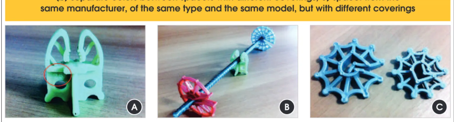
Although no standard requires the spacer to be identiied, beyond the identiication of the product’s covering, when the same model is con
-cerned, but with diferent covering values, these must have distinct colors as indicated in Figure 3b. This way, prevents that one speciied
spacer is confused with another during concreting operations with
dif-ferent thicknesses of covering, a situation similar to Figure 3c.
2.3 Fixity
The spacer must have the capacity to ixity the reinforcement bars
and resist the displacement of a steel bar with a load of 5 N [11]
[12]. As such, every spacer must possess an integrated ixity ele -ment so that it will attach to the reinforce-ments, without dropping
or losing its function, as illustrated in Figure 4. The ixity item (as
wire use) should not be the responsibility of the team responsible for the assembly of the reinforcements at the concreting, because
this would cause the risk of it not being executed. That is why an
integrated ixity is necessary.
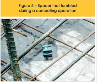
2.4 Stability
The spacer must have a minimum stability, so that when be re-quired during a concreting operation, it continues doing its part,
avoiding problems like tipping, shown in Figure 5.
2.5 Load capacity
The spacer must remain intact during the concreting process, resist-ing the load to which it is exposed - such as the weight of the rein-forcements, the assembly and concreting operations, the weight of workers and machines, among others - with a minimum estimated load of 3,0 kN (maximum strength suggested by CEB Bulletins #201 [12] and by the British Standard BS 7973-1 [11]) for spacers facing great demands, such as those used in concrete slabs and beam bot-tom (chair-type and multiple support spacers), and a minimum load of 0.25 kN (light strength suggested by the CEB Bulletins# 201 [12] and by the British Standard BS 7973-1 [11]) for spacers used on the sides
A
B
C
Figure 3 – Explanation of the identification requirement: a) size of the covering on the product;
(b) separate colors between spacers with different coverings; c) spacer from the
same manufacturer, of the same type and the same model, but with different coverings
of elements, such as circular spacers. These loads must be resisted under a maximum linear permanent deformation, in the direction of
the covering, of 1 mm [11][12], avoiding situations such as in Figure 6.
2.6 Application
The spacer must be easily applicable to steel bars. That way, there
is no need for a qualiied workforce for its application. To this end,
it should not require more than 0,15 kN (load applied by any adult) for their placement on the largest diameter of the bar reported by the manufacturer [11][12].
3. Experimental program
After establishing the performance requirements and criteria listed
in the previous sub-item, methods for their veriication and evalu -ation are proposed.
3.1 Dimensional requirements and criteria
Although the foreign standards do not say anything about the method of assessment of the dimensional requirements and crite-ria, the following methods were developed:
a) The method to assess the performance of the requirement
“provid-ing a s“provid-ingle cover“provid-ing value or at most two clearly identiied cover“provid-ing
values” consists of a visual inspection and analysis of the product design. The performance is considered satisfactory when the spac-er provides only one covspac-ering or, in the case of two covspac-erings in the
same spacer, these are clearly identiied on the product;
b) The method to assess the performance of the requirement “en-suring the nominal covering” consists of a dimensional inspec-tion by applying a steel bar to the spacer, after it is measured the distance (C) between the support base of the spacer and
the back of the steel bar, as in Figure 7, immediately before
and after the spacer, measured with a digital pachymeter with
Figure 5 – Spacer that tumbled
during a concreting operation
Figure 6 – Deformation of the spacer
because of the load in service
A
B
an accuracy of 0.02 mm. The performance is considered satis-factory when the covering provided by the product is equal to
the one speciied by the manufacturer, with a tolerance of ± 1 mm for coverings up to 75 mm and ± 2 mm for larger coverings;
c) The method to assess the performance of the requirement “mini-mum dimensions” also consists of a dimensional inspection which is performed with the aid of a digital pachymeter with an accuracy
of 0.02 mm, as in Figure 8. The performance is considered satis
-factory when the measures meet the values speciied in Table 1.
3.2 Identiication requirements and criteria
The method to assess the performance of this requirement con-sists in a technical inspection of the product. If it has the nominal
cover information visible and a diferent color than other spacers of
the same model, then this is considered to be satisfactory, other-wise it is considered unsatisfactory.
3.3 Fixity requirements and criteria
The method of assess the performance of this requirement con-sists in a technical inspection and analysis of the product design
to verify if the spacer has an integrated ixity item. If it does not
have some type of integrated mount, then it will automatically be
considered unsatisfactory. However, if the product has a ixity item,
then the evaluation method will proceed according to the test pro-posed by the CEB Bulletins #201 [12] and the British Standard BS 7973-1 [11], which applies a clean steel bar to the spacer with a smaller diameter that should be applied to the spacer according
to the manufacturer, with a weight of 5 N ± 0.1 N, as in Figure 9.
If the spacer prevents slippage of the bar, then this is considered satisfactory, otherwise it is considered unsatisfactory. The param-eter of the assessment method does not contemplate tolerances.
3.4 Stability requirements and criteria
The method to assess the performance of this requirement con-sists in dimensional inspections with the aid of a digital pachymeter
with an accuracy of 0.02 mm, as speciied in CEB Bulletins #201
[12] and British Standard BS 7973-1 [11].
For a clip-on spacers, except for circular spacers, the stability is con -sidered ensured when a the spacer provide rotating radius at least 5 mm larger than the required cover. This radius should be provided by the spacer in the parallel and perpendicular dimensions to the
A
B
C
Figure 8 – Measurement of the dimensions of chair-type spacers:
a) measured parallel to the bar position; b) measured perpendicular to
the bar position; c) measured from center of support of the circular spacer
Table 1 – Dimensional parameters for the minimum design requirements
(CEB, 1990 and BS 7973-1, 2001)
Model Minimum measure of the base
Perpendicular to the steel bar Parallel to the steel bar
Chairs and multiple-support spacers ≥ 0.75 of the provided cover ≥ 20 mm and ≤ 350 mm
Circular Spacers – ≥ 0.5 of the provided cover
steel bar to which it is applied, as in Figure 10 (a, b and c).
Circular spacers do not require a minimum radius of perpendicular rotation to the bar, since the stability is provided by the width of the central support parallel to the bar, which must be greater than half
the covering provided, as shown in Figure 10d.
Spacers that do not possess a ixity item or do not meet the parameters
and performance criteria described are considered to be unsatisfactory.
3.5 Load capacity requirements and criteria
The assessment of the load capacity requirement is an adaptation of the method proposed by CEB Bulletins #201 [12] and British Standard BS 7973-1 [11], which consists of a laboratory test.
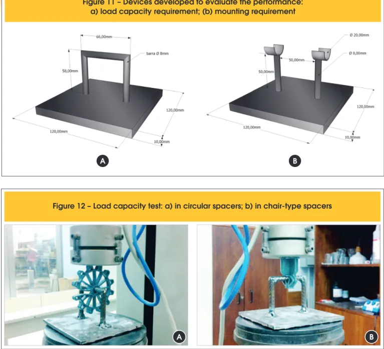
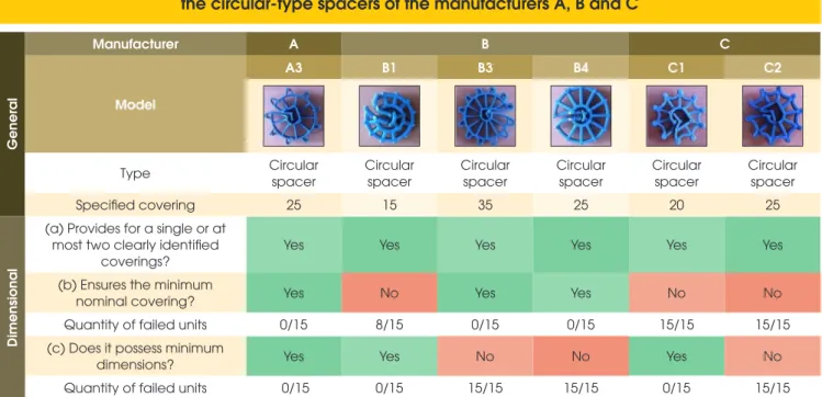
In order for the test to be performed, the irst device in Figure 11 was
developed, in which a steel bar of 8 mm from the device is applied
to the spacer, just as in Figure 12. Afterwards, the assembly (device
+ spacer) is placed into a press and a force is applied until reaching the load capacity required for the spacer according to Table 2. After the test is interrupted, either because of a rupture or because the load capacity is reached, the assembly is removed from the press and the maximum linear permanent deformation in the direc-tion of the covering is measured, which must be less than 1 mm. The press program generated stress versus deformation graphs concerning the behavior of the material.
Spacers that allow for two distinct coverings should be tested in their most unfavorable position, i.e., applied on the device according to the largest provided covering. Those products are considered satis-factory when that meet the established performance criteria.
A
C
B
D
Although the CEB Bulletins #201 [12] and the British Standard BS
7973-1 [11] use a diferent method for this assessment (Figure 13),
the test proposed above was designed in order to obtain graphs generated by the press on material behavior regarding its stress and deformation.
3.6 Application requirements and criteria
The method to assess the performance of this requirement con-sists of a laboratory test in which the spacer is supported on the
largest bar diameter recommended by its manufacturer. The
as-sembly is then inserted in a press, as in Figure 14, and the load is applied until the complete it of the spacer on the steel bar.
The product is considered satisfactory when no more than 0,15 kN of force is required for its full application.
Although the CEB Bulletins #201 [12] and the British Standard
BS 7973-1 [11] do not indicate a speciic method to evaluate this
requirement, the proposed test was designed in order to have a method to assess this requirement. As such, a second device was
developed as speciied in Figure 11.
Figure 11 – Devices developed to evaluate the performance:
a) load capacity requirement; (b) mounting requirement
A
B
!"#$"%"$&'&(&)"*+$$, "(%"$(-.*+$/"
-type spacers
Table 2 – Parameters for the maximum load value applied in the
test of the assessment method of the load capacity requirement
Spacer Demand Load capacity
Chair and multiple – support spacers Heavy 3.0 kN
Figure 13 – Apparatus for testing the load capacity [11][12]
A
B
3.7 Validation of the evaluation methods for
the assessment of spacer performance
In order to validate the proposed evaluation methods, 18 spacer models of 5 distinct manufacturers (A, B, C, D and E) and 10 more models of unidentified suppliers (X) were tested. All spacers were obtained from construction works that coop-erated with the study and consist of 10 chair, 13 circular and 5 multiple-support spacer models.
Following the CEB Bulletins #201 [12] criteria, a minimum of 10 units of each speciic model were tested in accordance with the
proposed assessment method, and with at least 90% of the units having to meet the proposed requirements.
Whenever a sample (of at least 10 units of the product) failed to
meet the requirements speciied above, the whole batch of spac -ers was rejected and considered unsatisfactory.
4. Results and discussion
Table 4 – Results of the design requirement evaluation of the chair-type
spacers of the manufacturer E and of unknown manufacturers
General
Manufacturer E X
Model
E2 X1 X2 X9 X10
Type Chair Chair Chair Chair Chair
Specified covering 15 | 20 25|30 20 20 20
Dimensional
(a) Provides for a single or at most two clearly identified
coverings?
No No Yes Yes Yes
(b) Ensures the minimum
nominal covering? Yes Yes Yes Yes Yes Yes Sim
Quantity of failed units 0/15 0/15 0/15 0/15 0/15 0/11 0/15
(c) Does it possess minimum
dimensions? Yes Yes Yes Yes Yes
Quantity of failed units 0/15 0/15 0/15 0/15 0/15 0/11 0/15
Table 3 – Results of the design requirement evaluation of
the chair-type spacers of the manufacturers A, B and C
General
Manufacturer A B C
Model
A1 A2 B2 B5 C4
Type Chair Chair Chair Chair Chair
Specified covering 15 20 15 20 20 25 30 20
Dimensional
(a) Provides for a single or at most two clearly identified
coverings?
No No Yes No Yes
(b) Ensures the minimum
nominal covering? Yes Yes Yes Yes Yes Yes Yes Yes
Quantity of failed units 0/15 0/15 0/15 0/15 0/15 0/15 0/15 0/15
(c) Does it possess minimum
dimensions? Yes Yes Yes Yes Yes
In this section, the results obtained per requirement are presented and discussed.
4.1 Dimensional
In Table 3 and Table 4 the performance assessments of the chair-type spacers can be found. They reveal that the mod-els A1, A2, B5, E2 and X1 didn’t satisfy the first design re-quirement. All the chair-type spacers were approved in the evaluation of the second and third design requirements, however.
For the circular spacers, the results of the performance assessments
of the design requirement can be seen in Table 5 and Table 6. One
can see that all models were approved in the irst design require -ment. In the second requirement, on the other hand, only models A3, B3, B4, D3 and E1 proved satisfactory results. In the last design requirement, only the models B3, B4, C2, D3 and X3 were rejected. The performance evaluation of multi-support spacers can be read in Table 7, which reveals that all models had satisfactory results for
the irst and third design requirement. However, in the evaluation of
the second design requirement, only the models D1 and D2 were rejected and thus considered as unsatisfactory.
Of the 28 evaluated spacer models, therefore, 10 were approved for all design requirements (B2, C4, X2, X9, X10, A3, E1, C3, E3
Table 5 – Results of the design requirement evaluation of
the circular-type spacers of the manufacturers A, B and C
General
Manufacturer A B C
Model
A3 B1 B3 B4 C1 C2
Type Circular spacer Circular spacer Circular spacer Circular spacer Circular spacer Circular spacer
Specified covering 25 15 35 25 20 25
Dimensional
(a) Provides for a single or at most two clearly identified
coverings?
Yes Yes Yes Yes Yes Yes
(b) Ensures the minimum
nominal covering? Yes No Yes Yes No No
Quantity of failed units 0/15 8/15 0/15 0/15 15/15 15/15
(c) Does it possess minimum
dimensions? Yes Yes No No Yes No
Quantity of failed units 0/15 0/15 15/15 15/15 0/15 15/15
Table 6 – Results of the design requirement evaluation of the
circular-type spacers of the manufacturers D, E and unknown manufacturers
General
Manufacturer D E X
Model
D3 E1 X3 X4 X5 X6 X7
Type Circular spacer Circular spacer Circular spacer Circular spacer Circular spacer Circular spacer Circular spacer
Specified covering 40 20 20 20 30 20 15
Dimensional
(a) Provides for a single or at most two clearly identified
coverings?
Yes Yes Yes Yes Yes Yes Yes
(b) Ensures the minimum
nominal covering? Yes Yes No No No No No
Quantity of failed units 0/15 0/15 2/10 13/14 14/14 15/15 3/15
(c) Does it possess minimum
and X8) and the other 18 were considered unsatisfactory in at least one evaluation for this requirement.
4.2 Identiication
In the evaluation of the identiication requirement, no evaluated
spacer model had the nominal covering on the product itself.
With respect to the color diferentiation in a same model, but with diferent coverings, none of the identiied manufacturer (A, B, C, D
and E) provided this distinction between their models. The same
cannot be said for the unidentiied manufacturers (unknown manu -facturers), because as the producer was unknown, the products of the same model could not be tracked down.
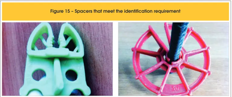
Although no evaluated model satisied this requirement, there are
spacers that would be approved in the assessment, as shown in
Figure 15. These were not assessed, however, because the sam
-ple was insuicient for evaluation.
4.3 Fixity
As none of the evaluated models provided a manufacturer’s
speci-ication in relation to the minimum reinforcement diameter to which
the spacers could be applied, the smallest diameter allowed for brackets was adopted, 5 mm according to ABNT NBR 6118 [17]. Table 8 and Table 9 show the mounting requirement evaluations for the chair model. Although the models B2, C4, X9 and X10 had a mounting item, it was not able to prevent the slipping of the steel bar. No model satisfactorily met the requirements and criteria established, therefore, with all being rejected according the proposed evaluation method.
For the circular models, on the other hand, the result of the evalua -tion can be found in Table 10 and Table 11. As the circular models have a mounting item, all were tested and most were approved. Models D3 and X3 were rejected, however, because they didn’t resist the displacement of the steel bar.
Just as the chair-type spacers, all multi-support models failed this performance test. The unsatisfactory performance was established immediately as none possessed a mounting item, as can be seen in Table 12.
Table 7 – Results of the design requirement evaluation of the multi-support-type
spacers of the manufacturers C, D, E and unknown manufacturers
General
Manufacturer C D E X
Model
C3 D1 D2 E3 X8
Type Multi-support Multi-support Multi-support Multi-support Multi-support
Specified covering 25 15 20 25 25
Dimensional
(a) Provides for a single or at most two clearly identified
coverings?
Yes Yes Yes Yes Yes
(b) Ensures the minimum
nominal covering? Yes No No Yes Yes
Quantity of failed units 0/12 15/15 15/15 0/15 0/15
(c) Does it possess minimum
dimensions? Yes Yes Yes Yes Yes
Quantity of failed units 0/12 0/15 0/15 0/15 0/15
Table 8 – Results of the fixity requirement evaluation of
the chair-type spacers of the manufacturers A, B and C
General
Manufacturer A B C
Model
A1 A2 B2 B5 C4
Type Chair Chair Chair Chair Chair
Specified covering 15 | 20 15 | 20 20 25 | 30 20
Fixity
Does it have an integrated
mounting item? No No Yes No Yes
→ If yes, it prevents slippage
of the bar? N/A N/A No N/A No
Quantity of failed units 15/15 15/15 3/15 15/15 4/15
Table 9 – Results of the fixity requirement evaluation of the chair-type
spacers of the manufacturer E and of unknown manufacturers
General
Manufacturer E X
Model
E2 X1 X2 X9 X10
Type Chair Chair Chair Chair Chair
Specified covering 15 | 20 25|30 20 20 20
Fixity
Does it have an integrated
mounting item? No No No Yes Yes
→ If yes, it prevents slippage
of the bar? N/A N/A N/A No No
Quantity of failed units 15/15 15/15 15/15 4/11 6/15
Table 10 – Results of the fixity requirement evaluation of
the circular-type spacers of the manufacturers A, B and C
General
Manufacturer A B C
Model
A3 B1 B3 B4 C1 C2
Type Circular
spacer
Circular spacer
Circular spacer
Circular spacer
Circular spacer
Circular spacer
Specified covering 25 15 35 25 20 25
Fixity
Does it have an integrated
mounting item? Yes Yes Yes Yes Yes Yes
→ If yes, it prevents slippage
Table 11 – Results of the fixity requirement evaluation of the circular-type
spacers of the manufacturers D, E and unknown manufacturers
General
Manufacturer D E X
Model
D3 E1 X3 X4 X5 X6 X7
Type Circular
spacer
Circular spacer
Circular spacer
Circular spacer
Circular spacer
Circular spacer
Circular spacer
Specified covering 40 20 20 20 30 20 15
Fixity
Does it have an integrated
mounting item? Yes Yes Yes Yes Yes Yes Yes
→ If yes, it prevents slippage
of the bar? No Yes No Yes Yes Yes Yes
Quantity of failed units 15/15 0/15 10/10 0/14 0/14 0/15 1/15
Table 12 – Results of the fixity requirement evaluation of the multi-support-type
spacers of the manufacturers C, D, E and unknown manufacturers
General
Manufacturer C D E X
Model
C3 D1 D2 E3 X8
Type Multi-support Multi-support Multi-support Multi-support Multi-support
Specified covering 25 15 20 25 25
Fixity
Does it have an integrated
mounting item? No No No No No
→ If yes, it prevents slippage
of the bar? N/A N/A N/A N/A N/A
Quantity of failed units 15/15 15/15 15/15 15/15 15/15
Table 13 – Results of the stability requirement evaluation
of the chair-type spacers of the manufacturers A, B and C
General
Manufacturer A B C
Model
A1 A2 B2 B5 C4
Type Chair Chair Chair Chair Chair
Specified covering 15 20 15 20 20 25 30 20
Stability
Does it have stability? No No No No No
In general, of the 28 evaluated spacer models in the mounting re-quirement, only 17 models had a mounting item, of which only 11 (A3, B1, B3, B4, C1, C2, E1, X4, X5, X6 and X7) were approved.
4.4 Stability
For the stability requirement, the results of the evaluations of the
chair-type spacers are displayed in Table 13 and Table 14. As in-formed, no model was approved according to the proposed evalu-ation method.
Although all circular model possess a mounting item, which is es-sential for stability, only models A3, B1, C1, E1, X4, X5, X6 and X7 were approved according to the proposed evaluation method. The other circular models had an unsatisfactory performance, accord-ing to Table 15 and Table 16.
As they didn’t have a mounting item, the multi-support models were not even evaluated, being automatically considered as un-satisfactory, as can be seen in Table 17.
In short, the stability requirement evaluation resulted in 8 approved models and 20 rejected models according to the proposed evalu-ation method.
4.5 Load capacity
As deined, the assessment of this requirement is dependent on
two variables: resisted load capacity and maximum permanent
lin-ear deformation. For chair-type models, the results can be seen in
Table 18 and Table 19.
One can see that of the 10 models evaluated, only 2 (B2 and X9) showed a satisfactory performance in this requirement, while the remainder was considered unsatisfactory.
In Table 20 and Table 21 the load capacity results for the circular models can be seen.
Although most circular spacers resisted the minimum load re-quired, many had a permanent linear deformation that exceeded the maximum allowed limit. Only models C1 and X6, therefore, pre-sented a permanent linear deformation of less than 1 mm and were approved, presenting satisfactory performance.
No multi-support model was approved according to the evaluation method proposed, as can be seen in Table 22. Of all the types, this was the one that had the most variability with respect to the resisted load. This can be explained by the diversity of positions allowed for its application. This type of spacer can be positioned perpendicularly, in parallel, or diagonally to the bar.
In general, of the 28 spacer models evaluated in this requirement, 4 (B2, X9, C1 and X6) showed satisfactory performance and 24 had an unsatisfactory performance according to the established evaluation method.
4.6 Application
Stability
Does it have stability? No No No No No
Quantity of failed units 15/15 15/15 15/15 10/11 15/15
Table 14 – Results of the stability requirement evaluation of the
chair-type spacers of the manufacturer E and of unknown manufacturers
General
Manufacturer E X
Model
E2 X1 X2 X9 X10
Type Chair Chair Chair Chair Chair
Specified covering 15 | 20 25|30 20 20 20
Table 15 – Results of the stability requirement evaluation of
the circular-type spacers of the manufacturers A, B and C
General
Manufacturer A B C
Model
A3 B1 B3 B4 C1 C2
Type Circular
spacer
Circular spacer
Circular spacer
Circular spacer
Circular spacer
Circular spacer
Specified covering 25 15 35 25 20 25
Table 16 – Results of the stability requirement evaluation of the circular-type
spacers of the manufacturers D, E and unknown manufacturers
General
Manufacturer D E X
Model
D3 E1 X3 X4 X5 X6 X7
Type Circular
spacer
Circular spacer
Circular spacer
Circular spacer
Circular spacer
Circular spacer
Circular spacer
Specified covering 40 20 20 20 30 20 15
Stability
Does it have stability? No Yes No Yes Yes Yes Yes
Quantity of failed units 15/15 0/15 10/10 0/14 0/14 0/15 0/15
Table 17 – Results of the stability requirement evaluation of the multi-support-type
spacers of the manufacturers C, D, E and unknown manufacturers
General
Manufacturer C D E X
Model
C3 D1 D2 E3 X8
Type Multi-support Multi-support Multi-support Multi-support Multi-support
Specified covering 25 15 20 25 25
Stability
Does it have stability? No No No No No
Quantity of failed units 15/15 15/15 15/15 15/15 15/15
Table 18 – Results of the load capacity requirement evaluation
of the chair-type spacers of the manufacturers A, B and C
General
Manufacturer A B C
Model
A1 A2 B2 B5 C4
Type Chair Chair Chair Chair Chair
Specified covering 15 20 15 20 20 25 30 20
Load capacity
Does it have load capacity? No No Yes No No
Quantity of failed units 14/14 15/15 1/14 15/15 15/15
→ If yes, was the permanent linear deformation
less than 1 mm?
N/A N/A Yes N/A N/A
Load capacity
Does it have load capacity? No No No Yes No
Quantity of failed units: 15/15 15/15 15/15 0/11 15/15
→ If yes, was the permanent linear deformation
less than 1 mm?
N/A N/A N/A Yes N/A
Quantity of failed units 15/15 15/15 15/15 0/11 15/15
Table 19 – Results of the load capacity requirement evaluation of the
chair-type spacers of the manufacturer E and of unknown manufacturers
General
Manufacturer E X
Model
E2 X1 X2 X9 X10
Type Chair Chair Chair Chair Chair
Specified covering 15 | 20 25|30 20 20 20
Table 20 – Results of the load capacity requirement evaluation
of the circular-type spacers of the manufacturers A, B and C
General
Manufacturer A B C
Model
A3 B1 B3 B4 C1 C2
Type Circular
spacer
Circular spacer
Circular spacer
Circular spacer
Circular spacer
Circular spacer
Specified covering 25 15 35 25 20 25
Load capacity
Does it have load capacity? Yes No Yes No Yes Yes
Quantity of failed units 1/15 2/15 0/15 2/15 1/14 0/15
→ If yes, was the permanent linear deformation
less than 1 mm?
No N/A No N/A Yes No
Unlike the spacer models of the identiied manufacturers, the
models that were from unknown manufacturers were evaluated according to an alternative method because they didn’t contain information regarding the largest recommended diameter for their application. This method consisted of trial and error, with the spacer being progressively applied from the smallest to the
largest diameter until it could no longer be itted with the maxi -mum force required.
The results of the evaluation for the chair-type models are displayed in Table 23 and Table 24, which show that only models B2 and C4 were rejected, having an unsatisfactory performance.
For the circular spacers, models A3, B3, C1 and C2 were consid -ered unsatisfactory because they failed the performance evalua-tion. All other models were approved in this requirement, as can be seen in Table 25 and Table 26.
Table 21 – Results of the load capacity requirement evaluation of the circular-type
spacers of the manufacturers D, E and unknown manufacturers
General
Manufacturer D E X
Model
D3 E1 X3 X4 X5 X6 X7
Type Circular
spacer
Circular spacer
Circular spacer
Circular spacer
Circular spacer
Circular spacer
Circular spacer
Specified covering 40 20 20 20 30 20 15
Load capacity
Does it have load capacity? Yes Yes Yes No Yes Yes Yes
Quantity of failed units 0/15 1/15 0/10 2/14 0/14 1/14 0/14
→ If yes, was the permanent linear deformation
less than 1 mm?
No No No N/A No Yes No
Quantity of failed units 11/15 15/15 2/10 5/14 2/14 1/14 5/14
Table 22 – Results of the load capacity requirement evaluation of the
multi-support-type spacers of the manufacturers D, E and unknown manufacturers
General
Manufacturer C D E X
Model
C3 D1 D2 E3 X8
Type Multi-support Multi-support Multi-support Multi-support Multi-support
Specified covering 25 15 20 25 25
Load capacity
Does it have load capacity? No No No No No
Quantity of failed units 12/12 15/15 15/15 15/15 15/15
→ If yes, was the permanent linear deformation
less than 1 mm?
N/A N/A N/A N/A N/A
Quantity of failed units 12/12 15/15 15/15 15/15 15/15
showing no resistance to the application to the steel bar.
In short, only 6 models failed the evaluation for this requirement, while 22 were approved with a satisfactory performance.
5. Conclusions
No spacer model evaluated proved to be satisfactory for all re-quirements and criteria proposed. Considering the rere-quirements and performance criteria used as appropriate to evaluate the per-formance of the spacers, the spacers could be considered as one
of probably factors for not achieving the project cover on current constructions.
It is clear, however, that all and any requirement and criteria
estab-lished can be satisied, since at least one spacer model was approved in each evaluation, except for the identiication requirement, for which
Table 23 – Results of the application requirement evaluation
of the chair-type spacers of the manufacturers A, B and C
General
Manufacturer A B C
Model
A1 A2 B2 B5 C4
Type Chair Chair Chair Chair Chair
Specified covering 15 20 15 20 20 25 30 20
Application
Easy to apply? Yes Yes No Yes No
Quantity of failed units 0/15 0/15 15/15 0/15 15/15
Application
Easy to apply? Yes Yes
Yes, up to 6.3 mm ɸ
steels
Yes, up to 6.3 mm ɸ
steels
Yes, up to 12.5 mm ɸ
steels
Quantity of failed units: 0/15 0/15 0/15 0/11 0/15
Table 24 – Results of the application requirement evaluation of the
chair-type spacers of the manufacturer E and of unknown manufacturers
General
Manufacturer E X
Model
E2 X1 X2 X9 X10
Type Chair Chair Chair Chair Chair
Specified covering 15 | 20 25|30 20 20 20
Table 25 – Results of the application requirement evaluation
of the circular-type spacers of the manufacturers A, B and C
General
Manufacturer A B C
Model
A3 B1 B3 B4 C1 C2
Type Circular
spacer
Circular spacer
Circular spacer
Circular spacer
Circular spacer
Circular spacer
Specified covering 25 15 35 25 20 25
Application
Table 26 – Results of the application requirement evaluation of the
circular-type spacers of the manufacturers D, E and unknown manufacturers
General
Manufacturer D E X
Model
D3 E1 X3 X4 X5 X6 X7
Type Circular
spacer
Circular spacer
Circular spacer
Circular spacer
Circular spacer
Circular spacer
Circular spacer
Specified covering 40 20 20 20 30 20 15
Application
Easy to apply? Yes Yes
Yes, up to 12.5 mm ɸ
steels
Yes, up to 6.3 mm ɸ
steels
Yes, up to 12.5 mm ɸ
steels
Yes, up to 10.0 mm ɸ
steels
Yes, up to 8 mm ɸ
steels
Quantity of failed units: 0/15 0/15 0/10 0/14 0/14 0/15 0/15
Table 27 – Results of the application requirement evaluation of the
multi-support-type spacers of the manufacturers C, D, E and unknown manufacturers
General
Manufacturer C D E X
Model
C3 D1 D2 E3 X8
Type Multi-support Multi-support Multi-support Multi-support Multi-support
Specified covering 25 15 20 25 25
Application
Easy to apply? Yes Yes Yes Yes Yes
Quantity of failed units: 0/12 0/15 0/15 0/15 0/15
Considering the variety and diversity of spacers on ofer, in addi
-tion to the diferent behavior of each one, the need for a regulatory
standard for this product to outline the quality of spacers available
on the market is revealed. For this would promote an improvement
of the material, in addition to eliminating unsatisfactory products.
6. Acknowledgments
The authors would like to thank CAPES for supporting the
re-search, the UFRGS and NORIE, in particular, for providing
advisory services and providing the equipment, in addition to all those who helped in the development of this research.
7. References
[1] LI, K.; CHEN, Z.; LIAN, H. Concepts and requirements of du -rability design for concrete structures: an extensive review of CCES01. In: Material and Structure. Ed. 41, page 717-731. Beijing, 2007.
[2] ROSTAM, S. Service life design of concrete structures – A challenge to designers as well as to owners. In: Asian Journal of Civil Engineering (Building and Housing). Vol 6, No 5. 2005.
[3] MARSH, B. Speciication and achievement of cover to rein -forcement. In: Advanced Concrete Technology Set. Volume 1, Pages 1 – 9, 2003.
[4] CLARK, L. A.; SHAMMAS-TOMA, M. G. K.; SEYMOUR, D. E.; PALLETT, P. F.; MARSH, B. K. How can we get the cover
Disponível em: http://www.localsurveyorsdirect.co.uk/sites/
default/iles/attachments/reinforced%20concrete.pdf. Aces -so em: maio 2014.
[6] MERRETZ, W. Achieving concrete cover in construction. In: Concrete in Australia. Technical Feature: Concrete cover. Vol
36, Nº1. Austrália, 2010.
[7] MARAN, A. P.; Menna Barreto, M. F. F.; ROHDEN, A. B.; DAL MOLIN, D. C. C.; MASUERO, J. R. Análise da espes -sura do cobrimento de armadura em lajes com diferentes distanciamentos entre espaçadores e pontos de amarração. In: Revista IBRACON de Estruturas e Materiais, 2015.
[8] MENNA BARRETO, M. F. F. Avaliação de desempenho de
espaçadores plásticos: proposição e avanços de métodos
de avaliação. Dissertação (Mestrado). Universidade Federal do Rio Grande do Sul. Programa de Pós-Graduação em En -genharia Civil, Porto Alegre, 2014.
[9] VAQUERO, J. Separadores para hormigón estructural. Zun -cho n13. Septiembre, 2007.
[10] ASSOCIAÇÃO BRASILEIRA DE NORMAS TÉCNICAS. NBR 14931: Execução de estruturas de concreto – procedi-mento. Rio de Janeiro, 2004.
[11] BRITISH STANDARDS INSTITUTION (BSI). BS 7973:
Spac-ers and chairs for steel reinforcement and their speciication
– Part 1: Product performance requirements. UK, 2001. [12] COMITÉ EURO-INTERNATIONAL DU BÉTON (CEB).
Bul-letin d’Information No. 201 — Spacers, chairs and tying of steel reinforcement. Lausanne: Comité Euro-International du Béton, 1990.
[13] GIRIBOLOA, M. Espaçadores para armadura. In: Revista Equi -pe de Obra, Editora PINI, edição 62, São Paulo: agosto, 2013. .
[14] TINOCO, H. F. F.; FIGUEIREDO, E. J. P. Avaliação do des -empenho de sistemas de reparo e recuperação para estru-turas de concreto com corrosão das armaduras. In: WORK-SHOP SOBRE DURABILIDADE DAS CONSTRUÇÕES, 2., 2001, São José dos Campos. Anais... São José dos Cam-pos: ITA, 2002.
[15] SPEKKINK, D. Performance based design: Bringing Vitru-vius up to date. Performance Based Building Thematic Net-work. Domain 3 Report. Holanda: novembro, 2005.
[16] ASSOCIAÇÃO BRASILEIRA DE NORMAS TÉCNICAS.
NBR 15575: Ediicações Habitacionais: Desempenho – Par
-te 1: Requisitos Gerais. Rio de Janeiro, 2013.


![Figure 10 – Geometrical stability requirements for spacers with integrated mount [11][12]:](https://thumb-eu.123doks.com/thumbv2/123dok_br/18861051.417935/7.892.63.828.391.1135/figure-geometrical-stability-requirements-spacers-integrated-mount.webp)