Efect of wind in the design of reinforced
concrete buildings
Efeito do vento no dimensionamento de edifícios
de concreto armado
Abstract
Resumo
This paper presents the results from a parametric study carried in order to quantify how far errors in the design stage related to the consideration of the wind action may put at risk the response and safety of reinforced concrete buildings. Using an architectural model as reference and varying the number of loors of the building, the structural safety was evaluated as a function of the wind action intensity. Results showed that even for low-rise buildings, with 10 loors, ignoring the wind action can signiicantly jeopardize their behaviour and safety. Yet, for slenderer buildings, up to 30 loors, it can lead to catastrophic results, as the ruin of the structure by progressive collapse.
Keywords: wind, columns, reinforced concrete, buildings.
Este artigo apresenta os resultados de um estudo paramétrico realizado com o objetivo de quantiicar o tanto que erros na etapa de projeto relacionados com a consideração da ação do vento podem comprometer a resposta em serviço e a segurança de edifícios de concreto armado. Usando-se um modelo arquitetônico como referência e variando-se o número de pavimentos do edifício, a segurança estrutural foi avaliada como uma função da intensidade da ação do vento. Os resultados mostraram que mesmo para edifícios baixos, com 10 pavimentos, a desconsideração da ação do vento pode comprometer signiicativamente o comportamento e a segurança e que no caso de edifícios mais esbeltos, com até 30 pavimentos, pode levar a resultados catastróicos, como a ruína da estrutura através de colapso progressivo.
Palavras-chave: vento, pilares, concreto armado, edifícios.
a Universidade Federal do Pará, Belém, Pará, Brasil;
b Universidade Federal do Pará, Faculdade de Engenharia Civil e Ambiental, Tucuruí, PA, Brasil; c Universidade Federal do Pará, Faculdade de Engenharia Civil, Belém, PA, Brasil.
Received: 23 Jan 2016 • Accepted: 02 May 2016 • Available Online: 21 Nov 2016
L.S.TAPAJÓS a
J. A .T. FERREIRA b [email protected]
A. F. LIMA NETO b [email protected]
M. R. TEIXEIRA b [email protected]
1. Introduction
The progressive collapse is a partial or complete ruin mechanism of a structure caused by the located failure of a primary structural element (Li et al [1]). This leads to the redistribution of loads to the surrounding elements, which can collapse as well. In national and international literature there are several cases of serious struc-tural accidents in buildings with concrete structure (Kamari et al [2], Schellhammer et al [3], King and Delatte [4], Gardner et al [5]). Souza and Araújo [6] highlight that in Brazil, the amount of structur-al accidents is increasing and that their origins are mainly related to mistakes in design and construction stages. This recurs in other countries too, and as example it can be cited the work of Kaltakci et al [7], that analysing the causes of accidents in buildings under construction in Turkey, got to the same conclusions.
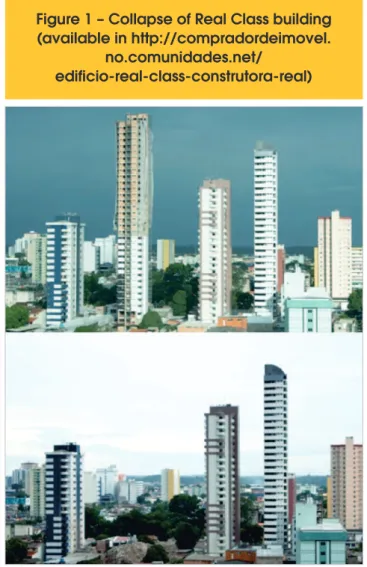
On January 29, 2011, in the city of Belem, Para, occurred one of the greatest structural accidents registered in Brazil in reinforced concrete buildings. On this day collapsed the residential building called Real Class, which was under construction, fatally victimiz-ing three people. Figure 1 shows the buildvictimiz-ing under construction and the landscape after its collapse. This building had constructed area of approximately 13,400 m² and was composed by 01
under-ground loor, 01 under-ground loor and 35 high loors, with about 105 m high. The building’s tower had its weight estimated in 9 thousand tons, which were supported by 25 columns.
The building’s ruin occurred during a heavy rain, where intense winds were registered in the city. In slender structures, the wind is one of the main actions to be considered (see Dyrbye and Hansen [8]) and there are records of various structural accidents with this action as origin (see Sha and Malinov [9], Klinger et al [10] and Rao et al [11]). At the time of this accident, three diferent teams carried out studies about the case and the analyses developed by a professors’ team of the Faculty of Civil Engineering from Federal University of Para indicated that the wind load was not properly considered in the design.
This paper presents results of a parametric study done in order to show how errors in the consideration of the wind action during the design stage can jeopardize the behaviour and the safety in the Ultimate Limit State of reinforced concrete buildings. A typical architectural plan was used as reference to develop the structural and foundations designs, having as one of the variables the num-ber of loors, varied between 10, 20 and 30 loors. The other vari-able of the study was the magnitude of the wind, which was initially assumed as zero, to deine the geometry and the amount of steel reinforcement of the structural elements, which were designed ac-cording to the recommendations of ABNT NBR 6118 [12]. Later, the wind action was considered as recommended by ABNT NBR 6123 [13] and the internal forces were used to verify the response in service and the safety of the structure and the foundations that were initially designed without wind consideration. The response in service and safety of columns and foundations is discussed.
2. Literature review
2.1 Wind
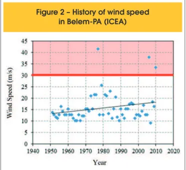
In the structural design, the wind is physically represented by a speed proile reaching a building. Its characteristics and the efects it generates depend on the velocity of the wind, the geometry of the building, and of the protection caused by the terrain and surround-ing obstacles. Rosa et al [14] warn that the environment has great inluence on the wind loads in a given building and that its accurate consideration is only possible if there are experimental data from tests in wind tunnel. On the other hand, Elsharawy et al [15] point out that even low building may sufer signiicant inluence of wind action, as in function of its plan geometry and columns positioning, wind action can induce torsional forces in the spatial frame. Although ABNT NBR 6123 [13] does not guide the use of automat-ed weather stations data, the ABNT NBR 5422 [16] alludes to this procedure in the recommendations for transmission lines designs. In this case, the currently used values to deine the country’s wind isotachs can be veriied by data from automatic stations, provided by institutions responsible for monitoring meteorological data. Fig-ure 2 shows wind speed data provided to the city of Belem-PA by ICEA [17], in the period of 1951-2010. It is possible to realize that the basic wind speed (V0) deined for Belem, which is 30 m/s, was exceeded three times in this period and that the average results seems to present increasing trend in function of time.
It is known that pressure made by wind is not static. It sufers luc-tuations (gusts) and depends on characteristics of its incidence on
Figure 1 – Collapse of Real Class building
(available in http://compradordeimovel.
no.comunidades.net/
structures (Elsharawy et al [18]). These pressure luctuations not only depend on the gust time, but also on the low regime (turbu-lence) and can cause the structure to sufer dynamic oscillations, inducing fatigue. In design situations, standards recommend the adoption of gust speeds in structural design, since structures in general have higher fundamental frequency of vibration than natu-ral wind frequency.
The intensity of wind forces in a structure varies spatially and tem-porally and, in design, most standards adopt a simpliied methodol-ogy where wind dynamic action is replaced by an equivalent static load. Through this procedure, it is attempted to represent the peak pressure caused by wind on the structure, being this pressure function of wind basic speed (V0), and of S1, S2 and S3 param-eters, as shown in Equation 1. This speed (V0) was established for the entire country through probabilistic approach and is deined as the 3-second-speed gust, exceeded on average once in 50 years, measured 10 m above the ground, in open and lat ield. Another important consideration on determining wind efects is the drag force, that in multistory buildings, describes the forces induced by the wind and should be calculated according to ABNT NBR 6123 [13] using Equation 2.
(1)
q=0.613·(V
0·S
1·S
2·S
3)
2(2)
F
a=C
aqA
Where:
Fa is the drag force,
Ca is the drag coeicient, obtained in function of the height and the plan dimensions of the building,
q is the velocity pressure,
A is the area of the reference surface.
S1, S2 and S3 are parameters deined in ABNT NBR 6123 [13] The determination of the drag coeicient is made depending on wind turbulence conditions. The ABNT NBR 6123 [13] deines that a building can be considered in high wind turbulence when its height does not exceed twice the average height of buildings in the vicinity, extending these, toward and in the direction of the incident wind, in a minimum distance of: 500 m, for a building up to 40-m-high; 1,000 m, for a building up to 55-m-40-m-high; 2,000 m, for a build-ing up to 70-m-high; and 3,000 m, for a buildbuild-ing up to 80-m-high.
2.2 Global stability
The veriication of reinforced concrete columns in tall buildings is inluenced by the overall stability of the building and can be neg-atively afected by 2nd order efects obtained with the calculation considering the deformed structure. ABNT NBR 6118 [12] presents two approximate procedures for checking the possibility of dis-pensing the consideration of 2nd order global forces: instability pa-rameter α; and coeicient γz. They are used to classify a structure
as being composed by ixed or mobile nodes and, in the case of
coeicient γz, it is considered that a structure has ixed nodes if γz ≤ 1.1. Feitosa and Alves [19] consider that the use of these param-eters in design is convenient, since the precise consideration of 2nd order efects may signiicantly increase analysis complexity. The coeicient γz can be determined using Equation 3, and in the case of structures with mobile nodes, since γz ≤ 1.3, 1
st order forces can be used to calculate the 2nd order ones, being scaled up by 0.95γ
z.
If the structure presents γz > 1.3, calculating 2
nd order efects must
be made using the P-Delta analysis method.
(3)
γ
z=
1
1-
D
M
M
tot,d1,tot,d
Where:
M1,tot,d is the 1st order moment, found by Equation 4, ΔM,tot,d is the addition of moments after 1
st order analysis, deter-mined by Equation 5.
(4)
(
)
1,,tot d
=
å
hid iM
F h
Where:
Fhid is the horizontal force applied on i loor, hi is the loor’s height h.
(5)
( )
,
Δ
M
tot d=
å
P u
id iWhere:
Pid is the acting vertical force on i loor, ui is the horizontal displacement of i loor.
2.3
Design of reinforced concrete columns
In buildings a column will usually be subjected to bending mo-ments in addition to the axial compressive forces due to not only asymmetry of spans and loads, but also because of horizontal ac-tions like the wind. In these cases, it is common for both design and veriication of load capacity to use bending-axial load interac-tion diagrams. These curves are obtained assuming points with diferent strain states in the cross section and computing for each of these points the axial force and the resultant moment in the sec-tion, as shown in Figure 3a for combined bending and axial load. In this igure, a random point A represents a combination of axial force and bending moment that would lead the column to ruin. In it, any combination of forces that results in a point inside the curve represents a safe load state and any point outside shows a com-bination of forces higher than the element’s load capacity. Radial lines as line OA represent the load eccentricity and point B shows the combination of forces for a balanced failure. Above this point, the failure is controlled by compression and below it, controlled by tension. Combination of forces up the line OC indicate critical situations where the ruin can occur without tensile strains of the element (no cracking).
In the case of columns under compression plus biaxial bending it is possible to draw a three-dimensional interaction surface from the interaction diagrams for the two main axes, as illustrated in Figure
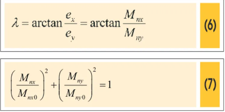
3b, for cases a and b. For case c, that combines moments in x and y directions, the resulting eccentricity’s direction is deined by the angle λ, calculated with Equation 6. Flexure in this case occurs on an axis deined by the angle θ. In practice, the construction of this three-dimensional surface of interaction can be complicated even using computational methods. In this paper, it was made in a simpliied manner, as described by Nilson et al [20] and presented in Equation 7.
2 2
0 0
1
æ
ö
æ
ö
+
ç
÷
=
ç
÷
ç
÷
è
ø
è
ø
ny nx
nx ny
M
M
M
M
Where:
Mnx = Pn ∙ ey
Mnx0 = Mnx when Mny = 0
A
B
Figure 3 – Iteration diagrams for reinforced concrete columns
Mny = Pn ∙ ex
Mny0 = Mny when Mnx = 0
3. Parametric study
3.1 Computational modelling
The methodology consisted of, based on an architectural plan of a building’s typical loor, designing the reinforced concrete structure and the foundations, entirely ignoring the wind action. This was done taking as variable the number of loors, generating spatial frames with 10, 20 and 30 loors, in order to highlight the relevance of the wind action in the design of reinforced concrete buildings. Later, the wind was considered in the computational models, fol-lowing the recommendations from ABNT NBR 6123 [13], show-ing how the behaviour and the safety levels of both structure and foundations can be in risk if this horizontal action is not properly considered in the design stage. These analyses were done using the commercial software AltoQi Eberick V9.
In the analyses without wind, the dimensions of the columns were pre-designed considering their inluence areas and assuming a constant vertical load on the loor. After this step, the structural design was regularly carried, yielding to the necessary dimensions and reinforcement ratios of the structural elements to safely sup-port the vertical forces. Subsequently, the interaction diagrams of all columns were generated, based on sections and steel
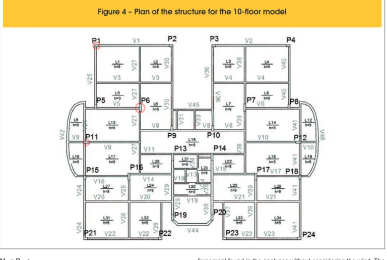
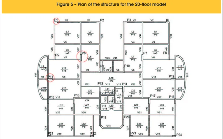
rein-forcement found in the analyses without considering the wind. The structural models were then analysed again, now considering the wind as established by ABNT NBR 6123 [13]. From these analyses the combinations of actions in each of the columns were extracted, for the evaluation of the structural safety. Also, the horizontal dis-placements of the structure were analysed, in order to evaluate its performance in service, the γz coeicient, as an indicative param-eter of instability, besides the increase of the 2nd order moments. Figures 4, 5 and 6 present the plans of the structures which were designed for models with 10, 20 and 30 loors, respectively, in the windless analyses. In these igures, columns selected for this ar-ticle’s presentation and discussion of results are highlighted with a red circle. A corner column (P1), a column near the loor’s edge (P11) and an inner column (P6) were chosen. Tables 1, 2 and 3 present the dimensions of these columns’ cross section and the steel reinforcement designed, for models with 10, 20 and 30 loors, respectively.
3.2 Criteria of ABNT NBR 6123 (1988)
The basic wind speed deined in ABNT NBR 6123 [13] as v0 = 30 m/s to the city of Belem, Para. To calculate the drag coeicient, the low regime was assumed as being of low turbulence and was calculated according to the Brazilian standard’s abacuses knowing that the plan dimensions of the loor are 20.80 m x 19.20 m. The correction coeicients for characteristic speed were:
n S1 = 1.00, related to lat terrains;
Figure 5 – Plan of the structure for the 20-floor model
n S
2 can be calculated by Equation 8. It is deined by the Brazil-ian standard as a function of the terrain’s roughness category and of the building’s dimensions. For the deinition of param-eters b, p, and Fr it was admitted that the terrain is category IV, characterized by being covered by numerous obstacles. For the 10-loor model, class B was adopted, and for the others, values corresponding to class C were used;
n S3 = 1.00.
(8)
2=
.
.
æ
ç
è
10
ö
÷
ø
P
r
z
S
b F
Where:
b, p and Fr are constants deined in the Brazilian wind standard; z is the height aboveground.
3.3 Criteria of ABNT NBR 6118 (2014)
According to ABNT NBR 6118 [12], for the determination of the 2nd order overall forces, the physical nonlinearity of materials can be considered in a simpliied way to reticulated structures with at least four loors, admitting to the calculation of structural elements the stifness values presented in Equations 9, 10 and 11.
Slabs:
(9)
( )
EI
sec=
0.3 . .
E I
c cBeams:
(10)
( )
EI
sec=
0.4 . .
E I
c cfor
A
s'
¹
A
sColumns:
(11)
( )
EI
sec=
0.8 . .
E I
c cWhere:
(EI)sec is the stifness of the element; Ec is the elastic modulus of concrete;
Ic is the moment of inertia of the gross cross section.
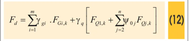
For forces’ determination, the combination of actions follows the formulas recommended by ABNT NBR 8681 [21], presented in Equation 12.
(12)
, 1, 0 ,
1 2
.
= =
é
ù
=
+
ê
+
ú
ë
û
å
må
nd gi Gi k q Q k j Qj k
i j
F
g
F
g
F
y
F
Where:
Fd is the calculation value of the action, γgi is the coeicient of permanent actions,
FGi,k is the characteristic value of permanent actions, γq is the weighting coeicient of variable actions,
FQ1,k is the characteristic value of the variable action considered as main action for the combination,
ΨojFQj,k is the reduced value of combining each of the other variable
Table 1 – Dimensions and steel of columns studied for the 10-floor model
Table 2 – Dimensions and steel of columns studied for the 20-floor model
Table 3 – Dimensions and steel of columns studied for the 30-floor model
Column Steel As (cm²) Section (cm) ρ (%)
P1 14 Ø 12,5 17,18 20 x 30 2,86
P6 16 Ø 20,0 50,27 20 x 70 3,59
P11 10 Ø 20,0 31,42 20 x 50 3,14
Column Steel As (cm²) Section (cm) ρ (%)
P1 18 Ø 16,0 36,19 20 x 50 3,62
P6 18 Ø 25,0 88,36 25 x 100 3,53
P11 36 Ø 16,0 72,38 25 x 80 3,62
Column Steel As (cm²) Section (cm) ρ (%)
P1 30 Ø 16,0 60,32 20 x 80 3,77
P6 26 Ø 25,0 127,36 30 x 120 3,54
actions.
For columns’ safety evaluation, it was considered that the design strength (Rd) should exceed the design load (Sd), as shown in Equation 13.
(13)
³
\
k³
.
d d f k
m
R
R
S
g
S
g
4. Results
4.1 Serviceability Limit State (SLS)
The serviceability limit states are related to people’s comfort and to the durability and good working conditions of the structure, con-sidering both users and machines installed in the building. ABNT NBR 6118 [12] recommends for concrete structures that the fol-lowing serviceability limit states are checked: crack formation limit state; crack opening limit state; excessive deformations limit state; decompression limit state; excessive compression limit state; and excessive vibration limit state.
For this article, it was admitted that the excessive deformations limit state would be dominant in relation to the others and it was evaluated using as analysis parameters the global displacement of the structure and γz coeicient, which is used to evaluate the importance of 2nd order global efects. ABNT NBR 6118 [12] admits that in mobile nodes structures with 1.1 < γz ≤ 1.3 it can be used to approximately determinate the 2nd order global forces.
Figure 7 presents the γz variation in x and y directions in function of the number of loors. It is possible to see that ignoring the wind action would cause that even the smaller building, with only 10 loors, had coeicient γz of 1.39, which requires that the 2nd order
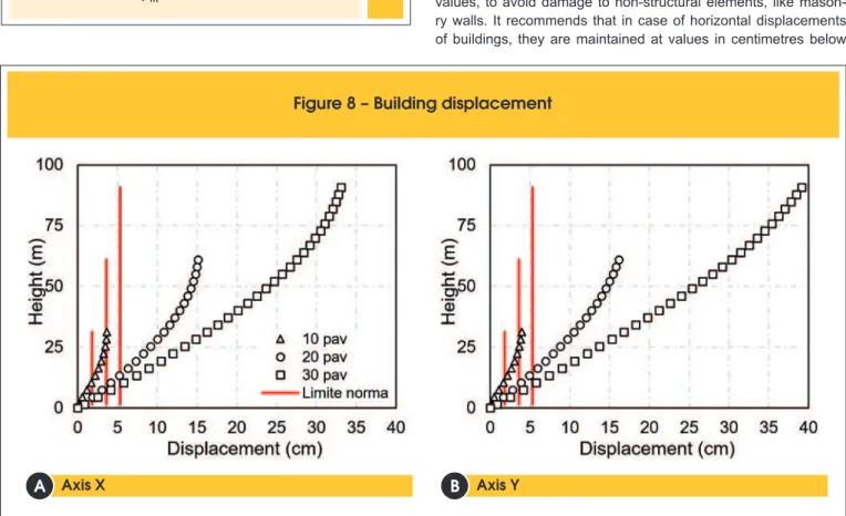
efects are determined by P-Delta analysis method. In the most extreme case, of the 30-loor model, values of γz up to 2.29 were found, indicating that the 2nd order efects would be extremely high. Figure 8 presents the variation of total displacements per loor con -sidering the wind action in x and y directions. ABNT NBR 6118 [12] recommends that displacements are maintained below limit values, to avoid damage to non-structural elements, like mason-ry walls. It recommends that in case of horizontal displacements of buildings, they are maintained at values in centimetres below
Figure 7 – Variation of gamma z coefficient
Axis X Axis Y
B
B
H/1700, which would result in maximum displacements of 1.8 cm, 3.6 cm and 5.3 cm for the buildings with 10, 20 and 30 loors, respectively. It is possible to see that considering the wind action, the horizontal displacements would be signiicantly bigger than the maximum values recommended by the Brazilian standard.
4.2 Ultimate Limit State (ULS)
The ultimate limit state is related to the collapse or any other ruin of the structure that leads to the interruption of its use. ABNT NBR 6118 [12] recommends for concrete structures to check the fol-lowing ultimate limit states: loss of static equilibrium; end of the structure’s load capacity, whole or in part, due to axial and tan-gential forces, assuming the redistribution of internal forces; end of the structure’s load capacity, whole or in part, considering the 2nd order efects; ultimate limit state caused by dynamic forces; ultimate limit state of progressive collapse; end of the structure’s load capacity, whole or in part, considering exposure to ire; end of the structure’s load capacity, considering seismic actions; other ultimate limit states that might occur in special cases.
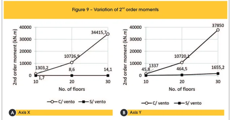
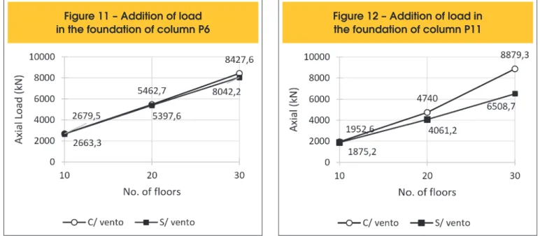
In the analyses carried in this paper, it was considered that the wind would cause the most signiicant efects on the ultimate limit state of columns. This way, both the increase in 2nd order moments and the possibility of ending the load capacity of columns under combined biaxial bending were evaluated. Figure 9 shows the in-crease in 2nd order moments caused by the wind action in x and y directions of the building, as presented in Section 2.2, pointing out how important it is to correctly consider in design the actions caused by wind. Signiicant increases in 2nd order moments were observed, which can really jeopardize the structure’s safety. Figures 10, 11 and 12 show the load increases in foundations of columns P1, P6 and P11, respectively, caused by the wind action. For column P6, there were no signiicant changes in the 3 models
possibly because it is an internal column, thereby sufering less inluence of the wind. However, for columns P1 and P11, in the 20-loor structure, for example, increases in vertical load of 31.5% and 16.7% were observed, respectively, when compared to cases with and without the wind action. And for the same situation, in the 30-loor building, increases of 75.3% in column P1 and 36.4% in column P11 were observed, which in practice could signiicantly jeopardize the safety level of foundations.
The structural safety level was evaluated in a simpliied manner by checking the load capacity of the columns under biaxial bending.
nd
Figure 9 – Variation of 2 order moments
Axis X Axis Y
B
B
A
B
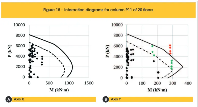
Columns P1, P6 and P11 were selected to illustrate the global re-sponse and for these elements diagrams of iteration were generat-ed, as illustrated in Figure 3. Figure 13 shows the resistance envel-opment for P1 in the case of the 10-loor building. In this and in the other igures, the dashed line indicates the design envelop, consid-ering the all safety coeicients and the solid line shows the strength considering the characteristic resistances of steel and of concrete. It is possible to see that for 4 combinations of actions the design load was bigger than the design resistance. This indicates that for these cases of load, the design safety level would not be satisied. In the case of the 20-loor building, the diagrams of columns P1 and
P11 are worth mentioning, which presented critical combination of actions, as show in Figures 14 and 15. In x direction of column P1, 4 combinations extrapolated the characteristic resistance of the column and other 2 the design one, whereas for the y direction only 1 combination was higher than the design strength. On the other hand, for column P11, only the y direction presented critical situations, with 4 combinations resulting in higher forces than the characteristic strength and 7 higher than the design one. This in-dicates that these columns would have a higher probability to ruin. For the 30-loor model, it was observed that the most critical situ-ations would also occur for columns P1 and P11 (see Figures 16
Figure 11 – Addition of load
in the foundation of column P6
Figure 12 – Addition of load in
the foundation of column P11
F
igure 13 – Interaction diagrams for column P1 of 10 floors
Axis X Axis Y
B
B
and 18), while for column P6 (see Figure 17) in all models, the iteration diagram showed that the acting force level would be lower than the design strength. The analyses carried out for the 30-loor building showed that also in the case of columns P1 and P11 the probability of ruin would be signiicant. In these cases, even more seriously, it is possible to realize that many of the critical points
would be related to abrupt ruin modes, governed by crushing of concrete without cracking of the columns.
5. Conclusions
This study shows in an objective way how the wind action afects
Figure 14 – Interaction diagrams for column P1 of 20 floors
Axis X Axis Y
B
B
A
B
Figure 15 – Interaction diagrams for column P11 of 20 floors
Axis X Axis Y
B
B
the response and the forces in the columns and in the founda-tions of reinforced concrete buildings. To the Serviceability Limit State, it can be concluded that ignoring the wind action in design stage can signiicantly jeopardize the stifness and the stability of the building, even in the case of short building with only 10 loors, where high horizontal displacements and expressive increase in
2nd order efects were observed. This could in practice jeopardize the comfort level of users, as Kwok et al [22] highlights, besides generating damage to non-structural elements, as masonry and window frames.
From the Ultimate Limit State point of view, there was expressive in-crease in foundations loads in edge and corner columns, resulting in
Figure 16 – Interaction diagrams for column P1 of 30 floors
Axis X Axis Y
B
B
A
B
Figure 17 – Interaction diagrams for column P6 of 30 floors
Axis X Axis Y
B
B
unacceptable levels of ruin probability. In the case of columns from the 30-loor building, it must be pointed out that many of the critical combinations would be related to ruins with the column’s section completely compressed, which would not generate any indication of risk to users. The analyses presented in this paper ignore some beneicial efects, such as the increase of stifness caused by brac-ing generated by masonry. Still, these results serve as warnbrac-ing to all Brazilian technical community about the importance of wind action consideration in concrete structures design.
6. Acknowledgments
The authors would like to thank the support to this and to other researches to: Universidade Federal do Pará (UFPA); to Núcleo de Desenvolvimento Amazônico em Engenharia (NDAE); to Núcleo de Modelagem Estrutural Aplicada (NUMEA); to Tucuruí Campus; to Eletronorte; and to the Funding agencies CNPq, CAPES and FAPESPA.
7. Bibliographic references
[1] LI et al. An improved tie force method for progressive col-lapse resistance design of reinforced concrete frame struc-tures. Engineering Structures, V. 33, pp. 2931–2942, 2011. [2] KAMARI et al. Reliability study and simulation of the
pro-gressive collapse of Roissy Charles de Gaulle Airport. Case Studies in Engineering Failure Analysis, V. 3, pp. 88-95, 2015.SHA, W.; MALINOV, S. Cantilever steel post damaged by wind. Case Studies in Engineering Failure Analysis, 2014, V. 2, pp. 162-168.
[3] SCHELLHAMMER et al. Another Look at the Collapse of Sky-line Plaza at Bailey’s Crossroads, Virginia. Journal of Perfor-mance of Constructed Facilities, V. 27(3), pp. 354-361, 2013.
[4] KING, S.; DELATTE, N.J. Collapse of 2000 commonwealth Avenue: Punching Shear Case Study. Journal of Perfor-mance of Constructed Facilities, V. 27 (1), pp 54-61, 2004. [5] GARDNER et al. Lessons from the Sampoong department
store collapse. Cement & Concrete Composites, V. 24(6), pp. 523–529, 2002.
[6] SOUZA, R.A.; ARAÚJO, M.J.S. The progressive failure of 15 balconies and the engineering techniques for their recon-struction. Engineering Failure Analysis, V. 18, pp. 895-906, 2011.
[7] KALTAKCI et al. An investigation on failed or damaged rein-forced concrete structures under their own-weight in Turkey. Engineering Failure Analysis, V. 14, pp. 962-969, 2007. [8] DYRBYE, C.; HANSEN, S.O. Wind Loads on Structures.
JOHN WILEY & SONS, 1997.
[9] SHA, W.; MALINOV, S. Cantilever steel post damaged by wind. Case Studies in Engineering Failure Analysis, V. 2, pp. 162-168, 2014.
[10] KLINGER et al. Failure analysis on collapsed towers of over-head electrical lines in the region Münsterland (Germany) 2005. Engineering Failure Analysis, V. 18, pp. 1873-1883, 2011.
[11] RAO et al. Investigation of transmission line tower failures. Engineering Failure Analysis, V. 17, pp. 1127-1141, 2010. [12] NBR 6118, Projeto de Estruturas de Concreto Armado.
As-sociação Brasileira de Normas Técnicas, Rio de Janeiro, 2014.
[13] NBR 6123, Forças Devidas ao Vento em Ediicações. Asso-ciação Brasileira de Normas Técnicas, Rio de Janeiro, 1988. [14] ROSA et al. Wind-induced dynamics and loads in a prismatic
slender building: A modal approach based on unsteady pres-sure meapres-surements. Journal of Wind Engineering and In-dustrial Aerodynamics, V. 107-108, pp. 118-130, 2012.
Figure
18 – Interaction diagrams for column P11 of 30 floors
Axis X Axis Y
B
B
[15] ELSHARAWY et al. Wind-induced torsional loads on low buildings. Journal of Wind Engineering and Industrial Aero-dynamics. V. 104-106, pp. 40-48, 2012.
[16] NBR 5422. Projeto de Linhas Aéreas de Transmissão de En-ergia Elétrica. Associação Brasileira de Normas Técnicas, Rio de Janeiro, 1985.
[17] Data from ICEA, available in http://clima.icea.gov.br/clima/ index.php.
[18] ELSHARAWY et al. Torsional and shear wind loads on lat-roofed buildings. Engineering Structures, V. 84, pp. 313-324, 2015
[19] FEITOSA, L.A.; ALVES, E.C. Estudo da estabilidade global de edifícios altos com lajes protendidas. Ibracon Structures and Materials Journal, V. 8, N. 2, p. 196-224, 2015.
[20] NILSON et al. Design of Concrete Structures. McGraw-Hill, 2010.
[21] NBR 8681. Ações e segurança nas estruturas – Procedi-mento. Associação Brasileira de Normas Técnicas, Rio de Janeiro, 2004.