Inluence of the lexibility of beams and slabs in static
response and dynamic properties
Inluência da lexibilidade de vigas e lajes na resposta
estática e propriedades dinâmicas
Abstract
Resumo
This article examines numerically the lexibility inluence of support beams in static response and dynamic properties of a symmetric plate formed by massive slabs of reinforced concrete in elastic linear regime, using the Finite Element Method. In the static response the variation of bending mo-ments and displacemo-ments are evaluated, which depend on the relationship between the lexibility of the slab and the beam. The evaluation of dynamic properties is held in undamped free vibration, through which the vibration modes and the values of the natural frequencies is obtained, which are compared with the limits of the Brazilian standard code for design of concrete structures. Results show that the response may show great variation due to the change in the relationship between bending stifness of the slabs and the beams.
Keywords: beams lexibility, massive slabs, static analysis, dynamic analysis.
Neste artigo estuda-se numericamente a inluência da lexibilidade de vigas de apoio na resposta estática e nas propriedades dinâmicas de um tabuleiro simétrico formado por lajes maciças e vigas de concreto armado, em regime elástico-linear, via Método dos Elementos Finitos. Na res -posta estática a variação de momentos letores e deslocamentos é avaliada, os quais dependem da relação entre a lexibilidade da laje e da viga. A avaliação das propriedades dinâmicas é realizada em vibração livre não amortecida, pela qual se obtêm os modos de vibração e os valores das frequências naturais que são comparadas com os limites da norma brasileira de projeto de estruturas de concreto. Os resultados mostram que a resposta apresenta grande variação devido à alteração da relação entre rigidez à lexão das lajes e vigas.
Palavras-chave: lexibilidade de vigas, lajes maciças, análise estática, análise dinâmica.
a Federal Technological University of Paraná – UTFPR, Civil Engineering Academic Department, Campo Mourão, PR, Brazil; b Federal University of Santa Catarina – UFSC, Civil Engineering Department, Florianópolis, SC, Brazil.
Received: 17 Sep 2015 • Accepted: 23 May 2016 • Available Online: 21 Nov 2016
J. R. BUENO a, b
D. D. LORIGGIO b
1. Introduction
The calculation of requested eforts on reinforced concrete plates is a task of great importance within the structural design of buildings, and under such perspective it is stressed the importance of con-sidering the deformability and eccentricity between these structural elements. There are studies that evidence the need to consider the lexibility between the slabs and beams in static response, [1], [2], [3], [4], and the dynamic properties/response, [5], [6], [7], but what
factors inluence it? Is the accuracy of the results undermined by the non-consideration of those efects? Moreover, how can they be considered in a coupled analysis on the plate? Those are some pertinent points when you want to study the efect of the lexibility of the support beams in the analysis and design of slab panels. Due to the peculiarities of each project, the references mentioned leave some gaps on recommendations and practices in relation to the subject, which is due to the diiculty of foreseeing on a realistic way the behavior of the slab/beam, system, including the efect of lexibility and eccentricity between slab and beam, mainly using manual calculations [8]. However, there is a need for standardiza-tion and recommendastandardiza-tions describing care, limits and practices for the calculation of plates consisting of reinforced concrete beams and slabs.
Therefore, the main objective of this article is to analyze the inlu-ence of the lexibility of beams and slabs in the static response and dynamic properties, for the design of reinforced concrete plates by means of the Finite Element Method (FEM).
2. Method
2.1 Static analysis
The static response of the plate, its eforts and displacements were obtained by means of linear analysis by using the SAP2000 software using FEM. The slab and beams displacements are elastic and the
inal displacement was calculated in accordance with NBR 6118 [9]. A plane model was used, where the slabs were modeled as inite quadrilateral elements of thin shell (Shell-Thin: 4 knots, 6 degrees of freedom per knot), based on the theory of Kirchhof, that does not consider the transversal deformation due to shearing [10]. The beams were modeled as a frame, which considers in these tests only the deformation due to bending.
In this type of model, the axes of the beams and the shell elements are in the same plane. Initially, the models were used without con-sideration of eccentricity between the slab plane and the axis of the beams. This eccentricity causes the beam to have a conjunct behavior with the slab, increasing the rigidity of the set. A common model, in order to take into account this efect in projects, is to consider a T section for the beam. In this work the efect cited was incorporated into the model, thus increasing the inertia of the beam according to equation (1), as reference [3].
(1)
In the analysis when the moment of inertia of the cross section of the beam (
I
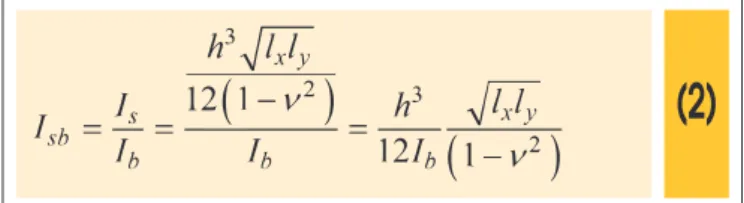
) was changed, the resistant module and the radius of gyration were also changed. Some of the results are displayed us-ing the indexI
sb that represents the lexibility coeicient between the slab and the beam, and is shown in equation (2) [2]. Theobjec-tive of this coeicient is to present the results of this paper without showing the dimensions of the slab and the beam that were used.
(2)
Where
n
is the Poisson coeicient,l
x andl
y are the slab di-mensions in the x and y direction, respectively, wherel
x is the smallest value;I
s is the slab lexibility index;h
is the thickness of the slab; andI
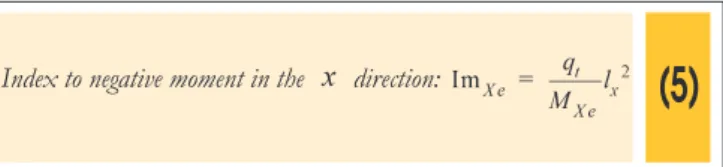
b the lexibility index of the beam (which is equal to moment of inertia). Dimensionless indexes were used in order to present the moments result’s (kN∙m/m) independent of thethick-ness of the slabs [2], as show in equation (3), (4) and (5), where
t
q
is the total load in slab. The use of these indexes allow a more comprehensive vision of the results, as it will be shown later.(3)
(4)
843
IBRACON Structures and Materials Journal • 2016 • vol. 9 • nº 6
(5)
The convention used in this work is that moments in a particular direc-tion (x or y) are the ones who will provide armor in this same direcdirec-tion,
x and y axes are shown in Figure 2. In the numerical analysis of this
article, the following efects have not been checked/considered: – Lifting of the edges of the slab in relation to its supports
(“dis-placement” between slab and beam). The connection between the structural elements is considered as monolitic;
– Shearing in slabs and cracking of structural elements;
– The inluence of the pillars section in the eforts of slabs and beams;
– Torsion stifness of the support beams: this is only a compat-ibility rigidity, not being essential for the equilibrium of the plate.
2.2 Dynamic proprieties
The dynamic proprieties of the plate correspond to the natural fre-quencies and vibration modes, and were obtained with the FEM
in which the problem of eigenvalues and eigenvectors is solved in undamped free vibration. The motion equation was obtained by
D’Alembert’s principle, equation (6), where [M] is the lumped-mass matrix [10], [K] is the matrix stifness, {ü} is the vector of
displace-ment and {ü} is the acceleration vector [11], [12].
(6)
The development of (6) leads to a polynomial equation of order N, with the roots wn called eigenvalues or characteristic values, and providing the N circular frequencies wn that can be sorted in ascending form be-ing w1 the smallest of them, known as circular fundamental frequency and harmonics higher than [12]. The displacement of the system can be obtained by a linear combination of vibration modes or eigenvectors. This property is used in a procedure called the modal analysis, con-strained to structures with linear behavior [13], [14], [15].
To verify the inluence of the response in each vibration mode, the modal participation factor (Mpf) was considered, which indicates how strong each mode is excited by its respective acceleration loads [10]. In the plate, not always the vibration mode that has the lower frequency of vibration is the one that should be used, but rather the one that
mo-bilizes more mass according to the direction of interest, which is the vertical direction or the global Z axis in the cases under consideration. For a given vibration mode and a global reference axis, X Y or Z,
, the modal participation factor is equal to the internal product (scalar product) of unitary acceleration along that axis and the vibration mode. To ensure a satisfactory behavior on the plate, a check of the ex-cessive vibration state-limit was performed, in which the funda-mental frequency of the structure (
f
1) in Hz unit, Table 1, should stay as far as possible of the critical frequency (f
crit), equation (7), according to NBR 6118 [9].(7)
For the lumped-mass matrix only the mass of elements given by multiplying the density by the volume was used. In the case of beams, the mass is grouped in the joints i and j (starting and end-ing node) and, for the slab’s mass it is grouped in the element nodes [10]. Inertial efects are not considered along the elements.
2.3 Plate characteristics
a – Slab: Continuous and rectangular (400x600 cm), Figure 2; b – Slab thickness: h = 10, 12 and 15 cm;
c – Board beams (rigid beams: V1, V2, V3 and V5): 15x250 cm;
d – Intermediate Beam V4: bw = 15cmand d is variable, with
min 15
d = cm and dmax = 150cm. By variation of rigidity of this beam it was studied the inluence of lexibility on the plate;
e – The board beams have a rigid connection with the pillars (sec-tion 20 x 20 cm), and V4 is supported by V1 and V2 with release of rotation;
f – Resistance to compression of concrete: fck = 20 MPa;
g – Secant modulus of elasticity: calculate by equation (8) where ae = 1 (granite):
(8)
0,8
0,8 5600
=
\
=
cs ci cs e ck
E
E
E
a
f
h – Poisson coeicient: n = 20;
i – FEM model: Slabs with a 12.5 x 18.75 cm rectangular mesh (ratio between the dimensions of the slab) and pillars are rep-resented as nodal points;
j – Total load on slabs qt (in kN m2):
, 10 12.50 t h
q = = ,
, 12
13
t h
q
==
, qt h,=15 = 13.75.For each slab thickness (item b) an analysis with the variation of V4
beam dimensions was realized (item d) and so, the static response and the dynamic properties of the system obtained.
3. Results And discussion
3.1 Static analysis
For the general analysis of the results the values obtained on static response are displayed as a function of the dimensionless index,
Table 1 – Critical frequency: structures
subjected to vibrations by the action of people
Use (Case) Critical frequency fcrit (Hz)
Fundamental frequency
f1 (Hz)
Office 4.00 4.80
845 IBRACON Structures and Materials Journal • 2016 • vol. 9 • nº 6
equation (2), generating a better visualization of the lexible
be-havior of the elements. Following, some explanations are made for reading and in order to enable a correct analysis of the igures. –
I
v4=
I
slabI
beam v4 corresponds to the ratio between thelexibility of the L1 slab with the lexibility of beam V4. The higher
the value of this index, the lower V4 beam height, and the lower
its bending stifness compared to the L1 slab, i.e. with an
in-crease of
d
, theI
v4 index decreases, Figure 3;– Legend for the igures: the terms
"h = 10, 12 15"h = and h= correspond to the thick-ness of the slab for which the results are displayed.
– The results obtained with the consideration of eccentricity are presented with the description
"[ ]"
e
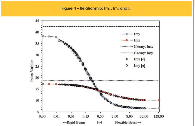
in the caption of the ig-ures, since other data refer to values without this consideration. The horizontal and/or vertical axis of some igures are displayed in logarithmic scale, base 2, so that trends and formations of techni-cal analysis are clearer. In other cases, it is used in the linear stechni-cale. Figure 4 shows the results for the dimensionless indexes Imx(Imx[e]) and Imy (Imy[e]) enabling a general analysis of the results, with easy viewing of the behavior of the variation of the eforts of the slab. It should be remembered that the indexes are inversely proportional to the bending moments, equation (3), (4) and (5). It is noted that it is possible to represent the results with just one curve, without having to display the values of
d
andh
of which the ef-forts are originated. The eef-forts obtained with consideration of [e] are smaller for displacements Mx and My and larger for Mxe whencompared to the computed values without this consideration. This behavior is related to the fact that, considering the
" "
e
results in a more rigid beam for the V4 support. The setting in which thesup-port beam V4 is more rigid is when you have the smallest thickness of slab due to greater eccentricity.
Figure 2 – Plate with continuous
slab panel of equal slabs (cm)
x
, Im and I
y v4847 IBRACON Structures and Materials Journal • 2016 • vol. 9 • nº 6
With the purpose of relating the diference between the consider-ation of the lexibility of supports with the manual calculconsider-ation, the moments that would be obtained by using the Czerny tables for slabs are also presented, these indices being constant due to not considering the deformability of the slab. Therefore, Figure 4 and Figure 5 show that the diference between the results obtained by
the FEM and the Czerny table can be signiicant, and that for the use of tables one must ensure that the support beams have signii-cantly higher bending rigidity than the slab.
When
IL
v4<
0.4181
the bending moment Mx is bigger than My,i.e., the bending moment in the direction of the smallest length is greater than the moment in the direction of the greater length (of
Figure 6 – (a) FEM and Czerny relationship; (b) Imxe index
A
B
the slab). This behavior is consistent with the expected to the loor,
once the slab tends to work in the direction of smallest length when the beam V4 has enough stifness. This same qualitative behavior is shown in the table results, where the supports are considered non-deformable. For
I
v4>
0.4181
we have My > Mx, that is, themoment in the direction of greater length becomes greater than in the direction of the smaller length. Counteracting the traditional calculation with the use of tables, since the intermediate beam does not provide suicient support.
The diference observed between the moments of the numerical
849 IBRACON Structures and Materials Journal • 2016 • vol. 9 • nº 6
model and the tables in Figure 4 for the condition of V4 practically
not deformable is because the results obtained by FEM are the maximum values of L1, which do not correspond to the center of the
slab, while the Czerny results are in the center. To show that when lv4 ≤ 0.187 the results of FEM and Czerny are virtually equal in the center of L1, the Figure 5 was elaborated. Only this igure presents
the results to the center of L1.
Both in Figure 4 and Figure 5 it can be seen the formation of a plateau when V4 has the height equal to the thickness of the slab, i.e.
d
=
h
. For this condition, which results inI
v4=
34.021
, the plate presents the coniguration of just one slab with dimension equal to 8x6 m. The positive bending moments Mx and My result in Imx = 10.06 and Imy = 6.50 indexes, respectively, for all thicknesses of the slabs. Thus, this igures allow the complete the study of the variation of the positive bending moments since the condition of V4non deformable until d
=
h
.With this data it is possible to answer the following question: what
is the error/diference associated with the non-consideration of lexibility and/or deformability of massive slabs, between the use of tables and FEM?
The answer is obtained with the help of Figure 6, which lists the results obtained by FEM and Czerny for the positive bending mo-ments (a) and negative (b) from the plate. It is noticed that, for the coniguration of greater rigidity of the plate the relationship be-tween the results obtained by FEM and Czerny is very close to one for Mx and My, and tends to one for Mxe.
For the latter, from lv4 ≤ 0.187 there is no way to relate the results
because the bending moment between the slabs becomes posi-tive, as can be seen in Figure 7 and thus, the plate works as if it
was composed of only a slab supported by the edge beams (V1, V2,
V3 and V5). In this situation, beam V4 fails to work as a support for L1 and L2 slabs and assumes the function of a slab rib.
Figure 8 shows the variation of displacements and eforts, x (M11) and y (M22) direction, as it reduces stifness of V4, which causes the
in-crease of the positive bending moments, inin-crease of displacements and decrease of the Mxe. An important aspect about the negative
mo-ments is that these are not uniform along the continuous edge be-tween the two slabs, as evidence the Figure 7 and Figure 8(a, d, g, j, m). These checks on the bending moments are important for the analysis of the plate since, when adopting an analysis that does not take into account the lexible behavior of the supports, it should be ensured that the beams have bending stifness. The representation of the bending moments and displacements with tracks of isovalues, Figure 8, allows the visualization of distribution of eforts, as it reduces the stickiness of V4. It is possible to verify that the point of maximum
displacement of L1 is not in the center of the slab, and when V4 is very
lexible (
I
v4>
0.4181
) this occurs in the center of the beam, with the same value for L1, L2 and V4, i.e., the point of maximumdisplace-ment for all eledisplace-ments coincides in the same place.
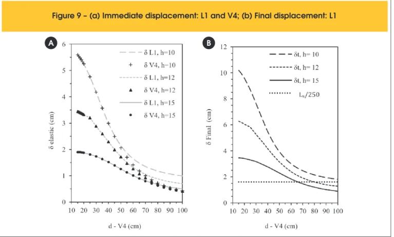
The immediate displacement (
a
t,0=
δ
), which is the maximumelastic displacement from the plate (L1 and V4) is presented in
Fig-ure 9(a). The highest values of displacements correspond to the coniguration of less rigidity, and these displacements present non-linear decreasing behavior as the plate increases its rigidity. This behavior is also evidenced in other studies [2], [5] and [6]. Figure 9(b) shows the total displacement of L1 (
a
t,∞=
δ
t), calculatedac-cording to equation (9), for an ininite time (t≤ 70 months) and
loading applied in
t
0=
6
months [9].Figure 9 – (a) Immediate displacement: L1 and V4; (b) Final displacement: L1
With this criterion, the displacements are multiplied by (1 + af) with af = 0.82, to consider the efect of luency [9]. Equation (9) should be used for displacements in reinforced concrete structures that have their displacements calculated from equivalent inertia, which presupposes knowledge of the armors. In this theoretical study, in which the armors are not deined, equation (9) was used only as a simpliied method to estimate the total displacement.
(9)
The permissible displacement according to [9], concerning the vi-sual sensory acceptability (
l
250
), to L1 is shown in Figure 9, inwhich, “l” is the length of the smallest slab interspace. Therefore, to meet the requirements regarding the excessive deformations of slabs, one must have δlim ≤ 1.6 cm. It turns out that, for h= 10cm the normative limit is not accomplished to any value of d. For
12
h= cm and d ≥ 80cmthis condition is met and with h= 15cm the condition is met for d ≥ 70cm. It is important to remember that one can appeal to the use of shoring to decrease the inal displace-ment.
3.2 Dynamic analysis
The results of the dynamic analysis, as the values of the funda-mental frequency (
f
1), are displayed in Figure 10. Those results conirm that, the more lexible the structure is the lower the val-ue off
1 with non-linear variation will be. This behavior was ex-pected, since from equation (6) it can be seen that the increased851 IBRACON Structures and Materials Journal • 2016 • vol. 9 • nº 6
rigidity of the structure will result in higher values of eigenvalues (frequencies).
The frequency values of the second and the third vibration mode are presented in Figure 11 and Figure 12 respectively. It is noticed that in a manner similar to the analysis of the eforts, displace-ments and frequencies of the irst mode, a nonlinear variation of the values of these frequencies is noticed for the second and the third modes.
The dynamic properties also are also afected when considering
" "
e
. With equation (1) it is determined that the increased rigidity of the structure without increasing the mass of the same, causes an increase in frequencies of vibration. The increase of the sec-tions of the structural elements causes a gain of rigidity to the sys-tem and at the same time adds more mass to this syssys-tem. What poses the following question: to what extent the values ofh
andd
(I
v4 values) can be increased and thus cause an in-crease in fundamental frequency of vibrationf
1?The answer is obtained by the analysis of Figure 10 to Figure 13. With Figure 10 it is veriied that for the
I
v4 relationships smaller than 0.0664 (h
=
10
), 0.0588 (h
=
12
) and 0.0523 (h
=
15
) the fundamental frequency (f
1) becomes constant, i.e. does not show variation with the increase ofd
. For the second vibrationmode (f2), Figure 11, a contrary behavior is shown, i.e. while f1
in-creased
f
2 remains constant and whenf
1 becomes constant the values off
2 increase.The third mode presents a level of constant values for frequencies with limits related to this baseline, close to the irst mode found. The participation of the third mode in the displacements in the ver-tical direction is pracver-tically nil.
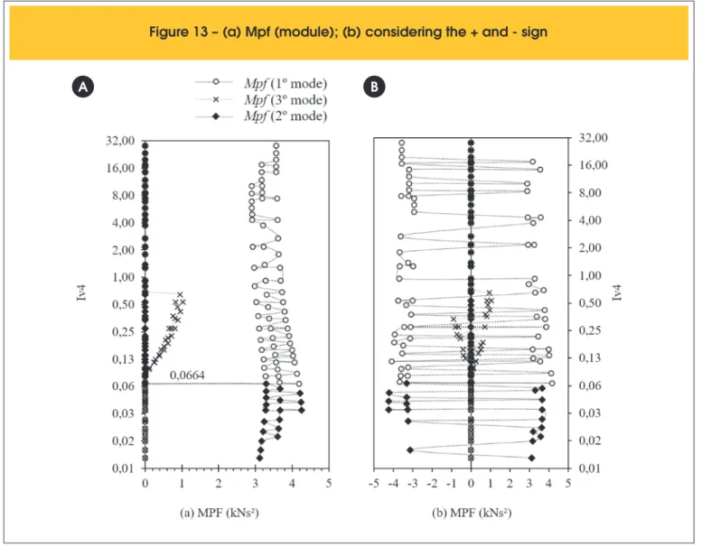
The reason for this behavior can be explained with the help of Figure 13, which shows the variation of the modal participation factor (Mpf), with values in module (a) and considering the sig-nal + or -, which depends on the parameterization mode without any signiicance to this study. In the igure it is observed that for
4
0.0664
v
I
>
the irst vibration mode will have a higher Mpfand when lv4 ≤ 0.0664 the second mode will have a greater Mpf . This means that when V4 has great bending stifness the second mode shall mobilize more mass according to the vertical direction (Z global axis) instead of the irst mode.
In relation to the condition of meeting the vibration limit state for use of the plate such as “Oice”, the structure is acceptable for any
4
v
I
relationship under study (Figure 10) since the minimum value of the irst vibration frequency required by the standard should bef
1>
4.8
Hz
(Table 1). In case of destination of the plate as!"# $" %&' (
d mode
“Dance Hall” (
f
1>
8.4
Hz
) the requirement is satisied for all the analyses withh
=
15
. Whenh
=
10
the threshold is met when50
d ³ cm and for
h
=
12
with d ≥ 45cm taking into account thevalues of irst frequency vibration mode. This comments are about the results without consideration of eccentricity.
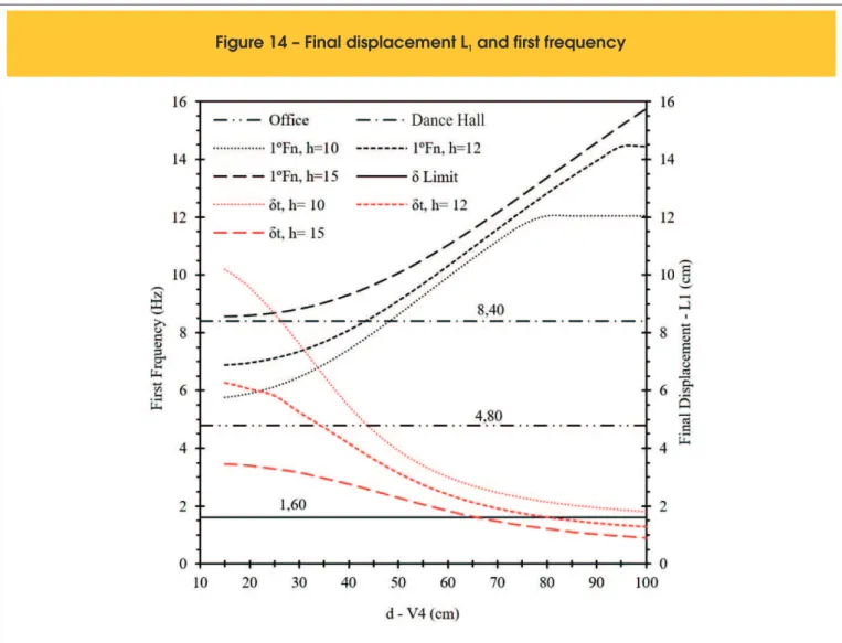
About the limits mentioned in reference [9] for static and dynamic properties, Figure 9 and Figure 10 show that the variation of the displacements and frequencies occurs in a manner contrary to each other. This means to say that, as it reduces the stifness of beam V4 the frequency values decrease and the displacements increase. It should be noted that the increase in rigidity of the plate is beneicial to the project, since the general goal is to have smaller displacements and higher frequencies. Therefore, it appears that for
h
=
10
andh
=
12
and a use as “Dance Hall” irst we will reach the static limit and after the dynamic limit, as the stifness of the plate is reduced. For using as “Oice” all settings of geometries attend the dynamic limit, as can be seen in Figure 14.This relationship between the static and the dynamic response is very important because to perform only static analysis of the loor it is possible to know if the dynamic limit was reached or not. The irst three vibration modes of the plate associated with the slab
thickness
h
=
12
are presented in Figure 15. From the analysisof the irst three modes it turns out that these are vertical modes and that the modes setting changes when the rigidity of beam V4
is increased.
4. Conclusions
It was found that the rigidity of the support beams of massive slabs has fundamental importance and contribution in the stifness of the plate and, consequently, modiies the static response and dynamic properties as well as how it does this modiication.
It turns out that the increased lexibility of the beams of the plate can change the direction of the greatest bending moments acting on the slab. This direction depends on the relationship between rigidity of slab and beam, and so, can be either in the direction of the smaller length or in the direction of the greater length. This behavior is related to the variation of the negative bending moment. Requesting eforts are distributed according to the rela-tive stifness between the elements that make up the structure, in case slabs and beams. The efort always will tend to concentrate
853 IBRACON Structures and Materials Journal • 2016 • vol. 9 • nº 6
Figure 13 – (a) Mpf (module); (b) considering the + and - sign
A
B
It was demonstrated that by using the traditional calculation tables of slabs for the determination of the stresses and displacements, it should be ensured that the support beams have signiicantly higher bending stifness than the slab. If that rigidity cannot be en-sured, it was shown the diference due to the lexible behavior of the support beams. It was shown that the negative bending mo-ment of the slabs is not uniform throughout the plate of continuity between slabs. So, when using the maximum value of this efort, for the entire edge, one can get a safe sizing, however, it may not be a cost-efective solution.
The dimensionless index
I
sb(I
v4) which relates the lexibility be-tween slab and beam, shows eicient representation of the results of the static response and dynamic properties, since these results may be displayed without the need to introduce explicitly the val-ues of slab thickness and height of beams, of which were carried out the analyses, although the indings are speciic to the model adopted. With theI
sb it was found to be possible to show the varia-tion of the modal participavaria-tion factor and analyze, for each relavaria-tion- relation-ship, which is the vibration mode that is mobilizing more mass for the vertical displacements of the slabs. For vibration frequencies identiied levels of values, and this result shows that, for certainI
sbrelations, it will not be the irst mode that will mobilize more mass according to the vertical direction, but other. These is the principal contribution of this paper.
The methodology adopted for this study is appropriate, since it is simple, it does not require great efort and can be easily implement-ed in the algorithms of structures analysis softwares. The method also takes advantage over more complex methods, such as the
Plate-Frame Model (PFM) and the Shell-Frame Model (SFM) [8].
Figure 14 – Final displacement L and first frequency
1It should be noted that these checks are related to the plate used and the criteria established for obtaining the results.
5. Acknowledgments
The authors thank the Conselho Nacional de Desenvolvimento Cientíico e Tecnológico (CNPq), the Federal University of Santa Catarina (UFSC), the Postgraduate Program in Civil Engineer-ing (PPGEC-UFSC) and the Federal Technological University of Paraná (UTFPR).
6. References
[1] Mazzilli, A. R. P. (1988). Inluence of deformability of the sup-port beams in the calculation of building structures. Disserta-tion (in Portuguese), University of Sao Paulo, Brazil. [2] Mazzilli, A. R. P. (1995). Inluence the lexibility of the beams
and slabs on the eforts of reinforced concrete structures. Thesis (in Portuguese), University of Sao Paulo, Brazil. [3] Araújo, J. M. (2008). Avaliação dos métodos simpliicados
para cálculo de lajes maciças apoiadas em vigas lexíveis. Teoria e Prática na Engenharia Civil 12: 1–11.
[4] Araújo, J. M. (2009). Método simpliicado para cálculo de lajes maciças apoiadas em vigas lexíveis: validação por meio da análise não linear. Teoria e Prática na Engenharia Civil 14: 71–81
[5] Paula, W. C. (2007). Structural behavior of ribbed reinforced concrete slabs based on the use of ANSYS software.
Dis-sertation (in Portuguese), State University of Rio de Janeiro. [6] Leite, M. R. S., Silva, J. G. S., Tavares, M. E. N., Soeiro, F. J.
C. P. (2010). Estudo do comportamento estático e dinâmico de lajes nervuradas de concreto armado. Mecánica Com-putacional Vol XXIX 9929-9937 (Buenos Aires).
[7] Amorim, A. B. A., Lopes, Fernanda R. C., Silva, J. G. S., Tava-res, M. E. N. (2010) Considerações de Projeto Sobre a Análise de Vibrações de Sistemas Estruturais de Pisos de Concreto Armado. In: Engenharia Estudo e Pesquisa 1: 56–67. [8] Tangwongchai, S., Anwar, N., Chucheepsakul, S. (2011).
Flexural responses of concrete slab over lexible girders through FEA-based parametric evaluation. KSCE Journal of Civil Engineering 6: 1057–1065.
[9] ABNT NBR 6118. (2014). Projeto de estruturas de concreto - Procedimento.
[10] Csi. (2009). SAP2000 Basic Analysis Reference.
[11] Hamedani, S. J., Khedmati, M. R., Azkat, S. (2012). Vibration analysis of stifened plates using inite element method. Latin American Journal of Solids and Structures 1: 1–20.
[12] Clough, R. W., Penzien, J. (2003). Dynamics of Structures, McGraw-Hill (New York).
[13] Lima, S. S., Santos, S. H. C. (2008). Análise Dinâmica das Estruturas, Ciência Moderna Ltda, (Rio de Janeiro)
[14] Chopra, A. K. (1995). Dynamics of Structures: Theory and applications to earthquake engineering, Prentice Hall (New Jersey).
855 IBRACON Structures and Materials Journal • 2016 • vol. 9 • nº 6
![Figure 4 shows the results for the dimensionless indexes Im x (Im x [e]) and Im y (Im y [e]) enabling a general analysis of the results, with easy viewing of the behavior of the variation of the eforts of the slab](https://thumb-eu.123doks.com/thumbv2/123dok_br/18861045.417929/4.892.63.437.172.532/figure-results-dimensionless-indexes-enabling-analysis-behavior-variation.webp)