The inluence of connecting pile cap-column
in the mechanisms of break in the two pile caps
A inluência da ligação pilar-bloco nos mecanismos
de ruptura de blocos de fundação sobre duas estacas
Abstract
Resumo
The paper analyzes the two pile caps with partially embedded socket and subject a center load. Three models were experimentally tested, varying the type of conformation of the column and walls of the socket, with a smooth, the other rough, and a monolithic two pile cap, used for reference. The roughening of the column-socket interface was examined with the aim of verifying the diference of the distribution of compressive and tensile stresses in the strut an tie model used for design. The experimental test to show that the two pile caps with conformation rough of the column and walls of the socket, support more load in comparison with two pile caps with smooth of the column and walls of the socket. Both however underperformed the monolithic two pile cap, with values of 66% and 36% respectively.
Keywords: two pile caps, reinforced concrete, foundations.
O trabalho analisa o comportamento de blocos sobre duas estacas com cálice parcialmente embutido, submetidos à ação de força centrada. Foram ensaiados experimentalmente três modelos, variando-se o tipo de conformação das paredes dos pilares e do cálice, sendo uma lisa, outra rugosa e um bloco monolítico, utilizado para referência. A rugosidade na interface pilar-cálice foi analisada, com o intuito de veriicar a diferença das distribuições dos luxos de tensões de compressão e tração no modelo de biela e tirante empregado no dimensionamento e, consequente -mente, o comportamento estrutural. As análises experimentais constataram que o modelo com conformação rugosa das paredes do cálice e do pilar apresentou capacidade resistente superior ao modelo com conformação lisa. Ambos, porém tiveram desempenho inferior ao bloco monolí-tico, com valores de 66% e 36% respectivamente.
Palavras-chave: blocos sobre duas estacas, concreto armado, fundações.
a CMEC, UFG, SRocha Consultoria e Projetos Ltda, Goiânia, GO, Brasil;
b Universidade Federal de Uberlândia, Faculdade de Engenharia Civil, Uberlândia, MG, Brasil; c Universidade Federal de Goiás, Regional Catalão, Faculdade de Engenharia, Catalão, GO, Brasil.
Received: 15 Oct 2015 • Accepted: 04 Mar 2016 • Available Online: 21 Nov 2016
A. C. MESQUITA a
www.srocha.eng.br
A. S. ROCHA a
www.srocha.eng.br
R. G. DELALIBERA b
W. A. DA SILVA c
1. Introduction
1.1 Initial considerations
The foundations are element to connections the superstructures and the soil and it is responsible in to transfer the actions in the structures. The foundations are separates in two groups: the su-pericial foundations and deep foundations. The distinction be-tween types are done about criteria the transmission the forces. In deep foundations the rupture not reaches the supericial layer of the soil. Usually, the rupture mechanism shown in the NBR 6122:2010 [1], reaches twice the small dimension of the founda-tions, so, the deep foundations are that in the your base of the foundation, are built with depth superior the three times the small dimension or superior the three meters.
The choice of the foundation for each building depends on several factors, such as construction technology available in the building area, economic conditions, geotechnical characteristics, intensity of actions, neighboring buildings, among others. With these factors and combinations of them, the engineer determines which type of foundation suitable for every situation.
Through studies on the choice of the type of foundation to be used in a particular construction, when the foundation is with piles, the construction of another structural element it is necessary: the pile caps. These pile caps are volume structures that have the func-tion of solidarity heads of the piles and transfer the acfunc-tions of the column to the piles.
Despite the importance of the pile cap, it does not allowed visual inspection when in service. Therefore, it is important to know their behavior. The models of design to this type of element are the strut and tie models and three-dimensional models.
The plan dimensions of the pile caps depend on the position of the piles, by adopting, in general, the smallest possible spacing between them to avoid the need to use suspension reinforced. This spacing is assumed equal to 2.5 times its diameter in the case of precast piles and 3.0 times the diameter if the piles are molded in place. When stabs the minimum distances between the piles, it avoids the group efect on the pile caps. It still must be a minimum distance between the faces of the pile and the end of the pile cap, in order to improve the conditions of the anchor of tie reinforced, as MUNHOZ [2].
The structural behavior and design depend on the rigidity of the pile cap, using the same criteria supericial foundation, according to ABNT NBR 6118: 2014 [3]. In the case of rigid pile caps can be adopted for the design and details of the pile caps, linear three dimensional structural models or nonlinear and strut and tie mod-els, these being preferred latter for deining with better eiciency distribution of forces within the pile cap. The NBR 6118: 2014 [3] does not bring in your text recommendations for veriication and design of this element only suggests that the criteria to be used and recommendations of the stress values in inferior (near the pile) and superior node (near the column). However, there are no rec-ommendations determining the geometric shape of the strut. Using model strut and tie, it is considered that the formation of dis-crete regions (known as D regions) that are the regions where the stress distribution is not linear and that are not valid hypotheses Bernoulli (known as regions B, where there linear change in ten-sion acting on the cross section). In this model, the checks of the compression stress of the strut are from the model Blévot & Frémy [4]. The stresses in the nodes zone, are suggested by NBR 6118: 2014 [3] and have lower values the stresses limits suggested by Blévot & Frémy [4], considering the deleterious efect of tensile stresses in the node zone with traction. However, near the nodal zones without traction, that is, node with stress compression only, the NBR 6118:2014 [3] does not consider the efect of concrete triaxial compressive stress, reducing the value in the node zone equal to
0, 58
n
cd
f
(or0, 27
n
n
v
f
cda
) in function of the Rüsch efect, in the efect of increased concrete strength with the time, in the factor form and in the diference between the test of specimens and the behavior of the structure. The Model Code CEB-FIP [5] suggests geometries for the nodes of nodal regions, being pos-sible to verify the stress in theses nodes.The strut and tie model can be used considering in the low of the stress in structure, using the minimal path forces, suggested by Schlaich et al. [6]. These stresses can be obtained through linear or no-linear analysis, using numeric methods, for example, the Fi-nite Element Method.
The used the precast structures, it is necessary, after the construc-tion of the pile and the pile caps, the setting of the column. After that, is necessary to ensure the ix of the column with the founda-tion. Then used a connecting element (The link between the pillar
and the pile cap may occur through the base plate, by amendment of reinforcing steel bars with grout and hem, by amendment of pro-truding reinforcement bars and socket, which will be studied in this work), whose main objective structural transfer of eforts between the pillar and pile cap, and allow the structural interaction between them. These connections are discontinuous regions where stress concentrations occur and form a ine point with respect to the di-mensioning and assembly of precast concrete structures, because they have great inluence on the structural behavior of the same. The union of the superstructure through socket, in the pile cap is accomplished by embedding a part of column (embedded length) in an opening of the foundation element that enables its holder. Usually the socket is built on the block, but is also used pile caps with embedded or partially embedded socket.
1.2 Objetivos
The objective of this study is to analyze and discuss the structural behavior of the connection column-pile cap through of type socket in two pile caps, using experimental tests.
2. Experimental program, materials
and methods
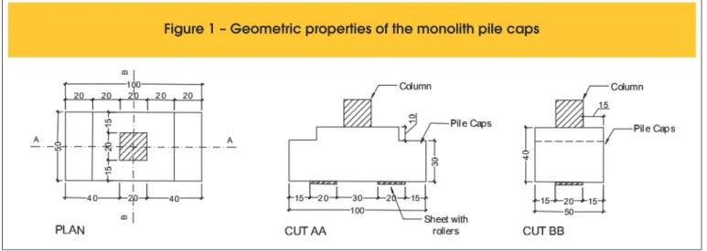
2.1 Geometric properties of te models
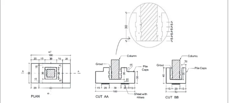
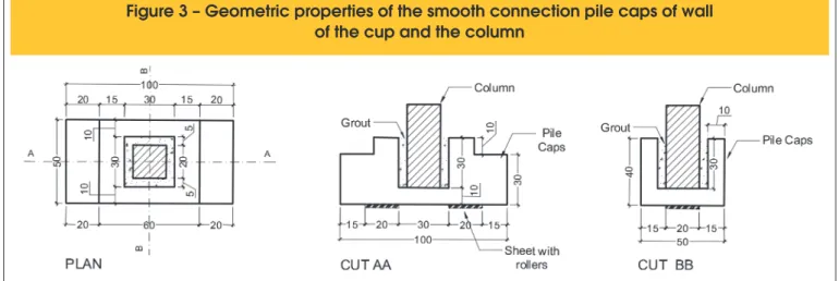
To this work, were buildings three models of the pile caps, one monolithic (column and pile caps concreted together – igure [1]), with reference models and two pile caps for precast column. One model for precast column has a socket-column interface with a rough surface (Figure [2]) and the other has socket-column inter-face with a smooth surinter-face (Figure [3]).
As suggested by EL DEBS [7], the wall of the cup (hc) should
be the greater of 10 cm and a third of the opening of the socket
socket (
3
inthx
and3
inthy
). Thus, the adopted value was equal to10 centimeters (Figure [4]).
The distance between the support of the piles was deined to the angle of the strut in the relation in the horizontal plane was equal α = 60,23°. This value is below the allowed limit by NBR 6118: 2014 [3], those angle is equal to 63,43°. Thus, the distance between the centers of the support of the pile was adopted equal to 50 cm. It was necessary this distance depending on the space limitations for the use of testing equipment within the laboratory.
The embedded length (
l
emb), deined by NBR 9062: 2006 [8], for precast columns with rough walls, is 40 centimeters. The roughness must be equal to 1 centimeter to 10 centimeters. How-ever, by design criterion, it adopted the embedded length (l
emb) of 30 cm and the roughness of 5 centimeters to 10 centime-ters. These values were adopted by the ease of construction of this surface in the industry or in place, using wood slats found com-mercially, with dimensions of 5:01 cm. Although the embedded length be less than that speciied by NBR 9062: 2006 [8], it is ac-cording to the EN 1991 [9], given by1, 2
h
x or1, 2
h
y, being hx and hy deined as the dimensions of the abut-ment.Another item recommended by NBR 9062: 2006 [8] for determin-ing the embedded length of column, refers to the length required for bond of reinforcing steel bars abutment for transferring stress to the pile cap. This length of embedded inlay must be greater than the length of bond. In this case, it was considering the diameter of the longitudinal steel bars equal the sixteen millimeter, type CA-50, conditions of the good bond and average compressive strength equal the 48 MPa, the value this length will be 18,4 centimeters.
The ABNT 6118:2014 [3] indicated the favorable efect of the strut near the column (describe in the item 9.4.2.5 and 22.7.4.14), in function the concentration of the stress compression in this region, may be applied the redactor coeicient to length bond, that by Fusco [10] is equal the 0,60, what resulted the eleven centimeters.
2.2 Concrete
The construction of the pile caps was made with Self-compacting concrete. This concrete it was produced in the CMEC Structures Laboratory (Master course in Civil Engineering – UFG). The used this concrete justiied by researches realized by CMEC about Self-compacting concrete. The materials to construction were donated by Redmix Concrete Brazil Inc. The characterization of materials and the study of concrete mix design they were made by Carlos Campos Laboratory Consulting and Design Ltd.
The mix of concrete used in the construction of the pile caps it was equal a 1:2,05:1.36;1.14;0,76:0,67 (cement, natural sand, artiicial sand, rock 0, rock 1 and water-cement ratio – a/c). To achieve the required luidity and cohesion were also used 0.6% of polyfunc-tional additive, the superplasticizer 0,4% and 6% active silica, both in relation to the Cement consumption.
The mechanics properties of concrete were obtained by test cy-lindrical specimens compressive, tensile strength by diametrical compression and elasticity module.
The average compressive strength and tensile concrete used in the molding pile caps, at 28 days, had values equal to 44,5 MPa and 4,04 MPa respectively. The elasticity module to 31,2 GPa. For the column was used grout industrial type Bautech brand with average compressive strength and superior traction of the pile caps with values equal to 48,0 MPa and 4,2 MPa. The measured elasticity module was equal to 22,0 GPa.
The structural elements were built separately: irst the pile caps, after the column, with your respective concretes.
After concrete curing and remove of the modes, the precast col-umns were placed in your respective pile caps and after to put grout in the socket.
2.3 Reinforcement
The steel bars used for reinforcement of the assembly were the Gerdau brand, donated by Prémoldaço Industry Precast Ltd. and assembled in the laboratory of CMEC structures (Master course in Civil Engineering – UFG).
Figure 3 – Geometric properties of the smooth connection pile caps of wall
of the cup and the column
The pile caps were detailing with four steel bars of 16 millimeters and steel CA-50 to tie reinforcement; the horizontals and verticals stirrups with diameters equal to 6,3 millimeters, with spacing
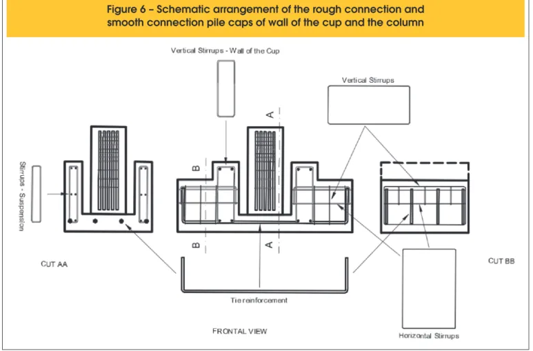
be-tween them equal to 10 centimeters. The Figure [5] to show the reinforcement used in monolithic pile cap and the Figure [6] the reinforcement of the precast models.
Figure 5 – Schematic arrangement of the monolith pile caps
The average yield stress (fyk) of the steel bars with 16 mil-limeters were equal a 559 MPa and yield strain (ey) was equal the 3,46 ‰. To steel bars with 6,3 millimeters, the value of the yield strain was equal the 2,77 ‰ and the yield stress equal the 523 MPa.
2.4 Molds
The molds to construction of the pile caps and columns were made with wooden plate plasticized plywood with thick of the 18 mm, in the CMEC Structures Laboratory.
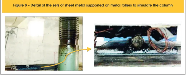
For the construction of the rough surface in the model with rough-ening of the socket and column, were put pieces of the Styrofoam with a thickness of 1,0 centimeters. Also were placed piece of the Styrofoam in the interface pile/pile cap, for subsequent itting of plate metal. These plates metals, which were supported on rollers, were thickness of 20,o millimeters.
2.5 Instrumentation
The deformations of the tie, the stirrups were analyzed by strain-gages of 5 millimeters of the base, trade maker Sensors Excel Ltd. The displacement horizontal and vertical of pile caps were ob-tained by ive dial gages.
The Figure [7] to show the positions were installed the strain-gages and the dial gages.
2.6 Experimental analysis
The experimental tests were realized in Materials and Structures Laboratory of Goias University, using hydraulic machine, with ca-pacitated of 3.000 kN and length piston equal to 1 meter. The loads were obtained by analogic dial of machine.
To simulate the pile of pile caps, were used two sets of metal plates, supported on rollers of metal. These sets served as support equipment for restricting the vertical displacement and allowing horizontal displacement.
The intention of rollers was simulate the rotation of piles in soil, after the loading of pile cap, by vertical and horizontal forces and bending, according with model to design.
The load was applied in the top of column, in steps of loads, di-vided every each 10 kN.
The Figure [9] shows the set of test.
3. Results and discussions
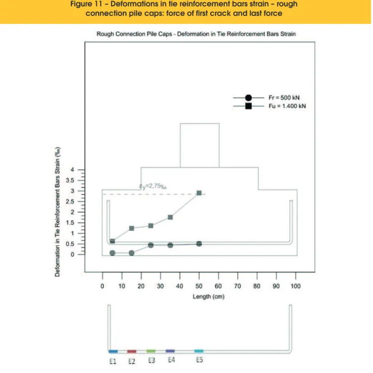
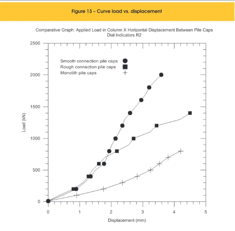
The monolithic specimens, to reference, showed greater load ca-pacity, when comparted with the precast pile caps. The model pre-cast pile cap, with the rough shaping of the walls of the socket and the column showed better performance than the model with the smooth conformation, but still below the monolithic model. The rupture load of the monolithic pile caps was equal to 2150 kN (Figure[10]), while the pile cap with roughened walls and column,
Figure 7 – Position of electrical-resistance strain gages and dial indicators in the pile caps
A
B
Figure 9 – Tests of two pile caps
Design of tests
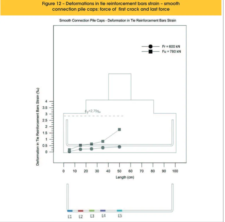
was load equal to 1420 kN (Figure [11]), a corresponding perfor-mance at 66 % compared to the monolithic model. But the pile caps with smooth conformation of the walls of the socket and the column, supported a load equal to 780 kN (Figure [12]), obtaining performance of the 36 % when compared to monolithic model. Similarly the pile cap model with smooth conformation of the walls of the socket and the column, showed performance 55%, when compared with rough pile cap.
The models of monolithic pile cap and precast pile caps with rough-ened walls, had collapsed by traction of strut, followed by concrete crushing. It was veriied that the occurred yield of the steel bars.
The precast pile caps with smooth walls, to show rupture fragile, by punching shear in the background pile cap, near the piles (Figure [13]). This fact is explained by deiciency of bond between walls socket and column, what result that the load in the column was to the background of pile cap and not making the struts.
In the Table [1], showed the relation between the ultimate load of pile caps and a comparison was performed between the same, with reference to the monolithic pile cap.
The pile caps tested were design using the Blévot & Frémy Model [4], considering that the struts between column and pile. The stress-es in the nodal zone were veriied by recommendations of the
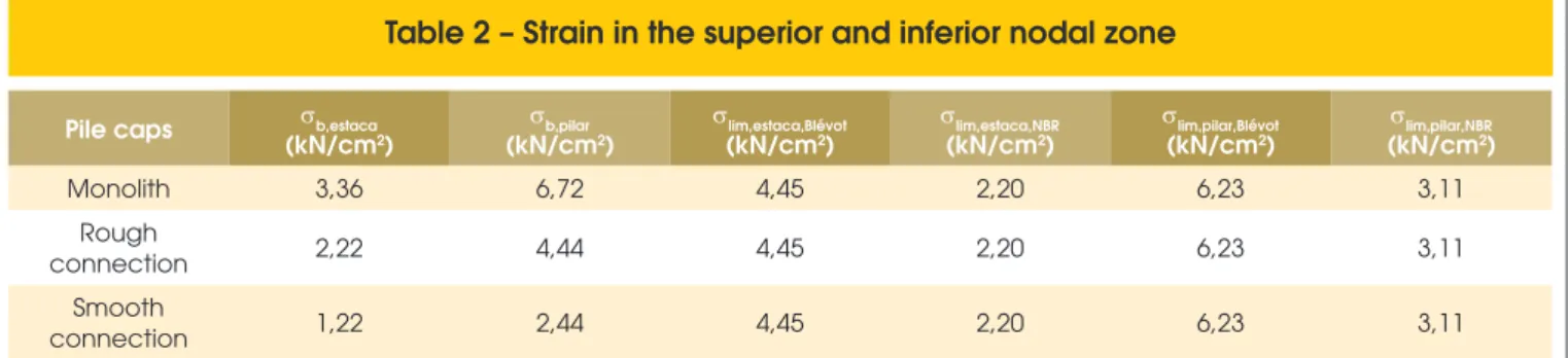
zilian Code – ABNT 6118:2014 [3].These analyzes are showed in the Table [2]. To design these stress, it not considered the increase coeicient of load and mitigation coeicients of the materials. In the Table [3], it was made the relations between the values of ef-fective stress in the limited stress. It was observed that the rupture of monolithic model occurred by diagonal traction of strut, followed of the crushing of strut and after the yield of the tie. (see Figure [10]). It was observed that the limited stress recommendations by Brazilian Code – ABNT 6118:2014 [3] are conservatives, because not was considered the behavior of the biaxial concrete in the su-perior nodal zone.
In the experimental tests of precast pile caps in this research, the Blévot & Frémy Model [4] not showed adequate results. With ref-erence to the monolithic model and stress limited established by Blévot & Frémy [4], the NBR 6118: 2014 [3], and the rupture load for each model, it was determined the theoretical inclinations of the strut and their respective heights useful and compared with experi-mental results. The results are show by Table [4] and Figure [14]. The results showed in the Table [3], indicate that the experimen-tal values, when compared with the theoretical values are fairly representative for the monolithic and rough models, when using the recommendations of Blévot & Frémy [4]. When analyzing the
values obtained when used the criteria to NBR 6118: 2014 [3], it was found that the pile caps should have greater rigidity to be the conditions of nodal security.
With respect to the forces on the ties, there was a signiicant reduc-tion when the steel bars of the tie through the inferior nodal zone near the pile. This reduction is caused by the favorable efect of the strut, which increases the frictional force at the interface of steel bars and concretes that region. Table [5] shows these results. The results presented in Table [5], corroborate the results obtained by Adebar et al. [11] Miguel [12] & Giongo Delalibera [13] Barros & Giongo [14] and Delalibera & Giongo [15].
4. Conclusion
The model monolith, taken as a reference, was as expected, due to the model to design used, based on Model Blévot & Frémy [4], with rupture load of 2,150.00 kN. The rupture was due to the trac-tion diagonal, followed by crushing of the strut concrete.
The model precast pile cap with rough of wall of the socket and column had underperformed the monolith model, with rupture load equal to 1420.00 kN. The ruptures occurred by diagonal traction of the strut, fol-lowing by crushing of strut concrete and yield of the steel bars of the tie.
The model precast pile cap with smooth conformation of wall of the socket and column, had performance below the monolithic model. The rupture load was equal to 780 kN. The rupture occurred by punching of the background of the pile cap, near of piles. The steel bar of the tie has not shown yield, but occurred slip.
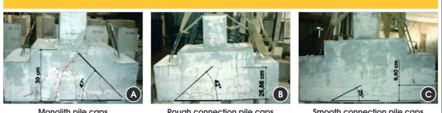
The transfer of the load of column to pile was eicient in the rough model. This indicates that the roughness of the socket and of column it worked as shear key, which allowed the formation of struts, a fact conirmed also by cracking mad of the tested model. For the pile caps with smooth conformation, the transfer of load of column to pile was ineicient, indicating the behavior of bend-ing and shear. Due to the small length of inlay, the conforma-tion smooth showed shear key, transferring the load directly to
background of the pile cap. This fact caused punching, what can be observed by cracking map in Figure [14]. Another fact which conirms this conclusion is the theoretical value calculated to in-clination of strut, depending on the rupture load, generating a lower value than recommended by Blévot & Frémy [4], as shown in Table [4].
It was found that the strength of the strut decreases the tensile force in the tie, due to the increased friction in the inferior nodal region. The models of the monolithic pile cap and precast pile caps with the roughened conformation of the walls of the socket and the column showed characteristic behaviors of rigid pile cap, as de-termined by NBR 6118: 2014 [3]: the existence of the concrete compression struts, diagonal cracks of column going to the pile
and lexion-compression on the piles.
But the model of the precast pile cap with the smooth conformation of the walls of the socket and the column showed similar behavior
to lexible pile caps. Thus, it is evident that when using this type of conformation should work with larger inlays lengths, thus avoiding the fragile collapse, by puncturing the model.
5. Acknowledgements
To: Higher Education Personnel Improvement Coordination – CAPES for the inancial support to perform the research that made it possible to write this paper.
To: Redimix Concrete Brazil S.A. for the supply of materials for molding the concrete used.
To Laboratory Carlos Campos Consultancy and Projects Ltd for the characterization of materials and the concrete dosage study. At Prémoldaço Industry Precast Ltd for the supply of steel bars used.
Table 1 – Load rupture of pile caps tested
Pile caps Fu (kN) Fu,Monolítoco/Fu
Monolith 2150 1
Rough
connection 1420 1,51
Smooth
connection 780 2,76
Table 3 – Ratio betweem in the nodal zone
Pile caps sb,estaca/slim,estaca,Blévot sb,pilar/slim,pilar,Blévot sb,estaca/slim,estaca,NBR sbpilar/slim,pilar,NBR
Monolith 0,76 1,08 1,53 2,16
Rough
connection 0,50 0,71 1,00 1,43
Smooth
connection 0,27 0,39 0,55 0,78
Table 2 – Strain in the superior and inferior nodal zone
Pile caps sb,estaca
(kN/cm2)
sb,pilar
(kN/cm2)
slim,estaca,Blévot
(kN/cm2)
slim,estaca,NBR
(kN/cm2)
slim,pilar,Blévot
(kN/cm2)
slim,pilar,NBR
(kN/cm2)
Monolith 3,36 6,72 4,45 2,20 6,23 3,11
Rough
connection 2,22 4,44 4,45 2,20 6,23 3,11
Smooth
connection 1,22 2,44 4,45 2,20 6,23 3,11
Notes:
sb,estaca, stress in the strut close to the inferior nodal zone; sb,pilar, stress in the strut close to the superior nodal zone; slim,estaca,Blévot, stress limite by Blévot & Frémy [4] method,
6. Bibliographical references
[1] ASSOCIAÇÃO BRASILEIRA DE NORMAS TÉCNICAS. ABNT NBR 6122:2010 – Projeto e execução de fundações. Rio de Janeiro, 2014.
[2] MUNHOZ, F.S. (2004). Análise do comportamento de blocos de concreto armado sobre estacas submetidos à ação de for-ça centrada. Dissertação (mestrado) – Escola de Engenharia de São Carlos, Universidade de São Paulo, São Carlos. [3] ASSOCIAÇÃO BRASILEIRA DE NORMAS TÉCNICAS.
ABNT NBR 6118:2014 – Projeto de estruturas de concreto. Rio de Janeiro, 2014.
[4] BLÉVOT, J.; FRÉMY, R. (1967). Semelles sur piex. Analles d’Institut Techique du Bâtiment et des Travaux Publics, Par-is, v. 20, n. 230.
[5] COMITE EURO-INTERNACIONAL DU BÉTON (1990). CEB-FIP Model code for concrete structures. Bulletin D’Information, Paris, n. 203-205, July.
[6] SCHLAICH, J.; SCHAFER, K.; JENNEWEIN, M. (1987). To-ward a consistente design of reinforced structural concrete. Journal of Prestressed Concrete Institute, v. 32, n. 3, May-June; [7] EL DEBS, M. K.; Concreto pré-moldado: fundamentos e
aplicações. 1ª ed. São Carlos, SP, Publicações EESC-USP, 2000.
[8] ASSOCIAÇÃO BRASILEIRA DE NORMAS TÉCNICAS. ABNT NBR 9062:2006 – Projeto e execução de estruturas de concreto pré-moldado. Rio de Janeiro, 2007.
[9] EN 1991-1-1. Eurocode 2: Design of concrete structures – Part 1-1: General rules and rules for buildings. European standard, 2004.
[10] FUSCO, P. B. (1994). Técnicas de armar estruturas de con-creto. Editora Pini Ltda., São Paulo.
[11] ADEBAR, P.; KUCHMA, D.; COLLINS, M. P. (1990). Strut-and-tie models for design of pile caps: an experimental study. ACI Journal, v. 87, p. 81-91, Jan/Feb;
[12] MIGUEL, G. M. (2000). Análise experimental e numérica de blocos sobre três estacas. Tese (doutorado) – Escola de En-genharia de São Carlos, Universidade de São Paulo, São Carlos;
[13] DELALIBERA, R. G.; GIONGO, J. S.. Deformation in the strut of two pile caps. IBRACON Structural an Material Jour-nal, v.1, n.2, p. 121-157, june, 2008.
[14] BARROS, R.; GIONGO, J. S.. Estudo experimental de blocos de fundação com cálice externo, embutido e par-cialmente embutido considerando interface lisa. IBRACON Structural an Material Journal, v.6, n.5, p. 737-764, October, 2013.
[15] DELALIBERA, R. G.; GIONGO, J. S.. Numerical analysis of two pile caps with sockets embedded, suject the eccentric compression load. IBRACON Structural an Material Journal, v.6, n.3, p. 436-474, june, 2013.
B
C
Figure 14 – Pile caps tested – identification of angle of inclination of the struts
A
Monolith pile caps Rough connection pile caps Smooth connection pile caps
Table 5 – Forces on tie reinforcement bars strain
Pile caps Rsty (kN) Rst,5 (kN) Rst,3 (kN) Rsty/Rst,5 Rst3/Rst,5 Condition
Monolith 449,57 346,93 238,30 1,89 0,69 Not yield
Rough
connection 449,57 449,57 162,42 1,0 0,36 Yield
Smooth
connection 449,7 217,00 42,88 2,07 0,20 Not yield
Rsty, tensile force on tie reinforcement bars strain, on yeld of reinforcement bars; Rst,5, tensile force on tie reinforcement bars strain, measured at 5 position (see Figure [07]);