Finite Difference Energy Method for nonlinear numerical
analysis of reinforced concrete slab using simpliied
isotropic damage model
Análise não linear numérica via MDFE de lajes de
concreto armado utilizando a mecânica do dano
a Universidade Estadual de Feira de Santana, Programa de Pós-graduação em Engenharia Civil e Ambiental, Feira de Santana, Bahia, Brasil.
Abstract
Resumo
This work presents a model to predict the lexural behavior of reinforced concrete slabs, combining the Mazars damage model for simulation of the loss of stiffness of the concrete during the cracking process and the Classical Theory of Laminates, to govern the bending of the structural ele
-ment. A variational formulation based on the principle of virtual work was developed for the model, and then treated numerically according to the Finite Difference Energy Method, with the end result a program developed in Fortran. To validate the model thus proposed have been simulated with the program, some cases of slabs in lexure in the literature. The evaluation of the results obtained in this study demonstrated the capability of the model, in view of the good predictability of the behavior of slabs in lexure, sweeping the path of equilibrium to the rupture of the structural element. Besides the satisfactory prediction of the behavior observed as positive aspects of the model to its relative simplicity and reduced number of experimental parameters necessary for modeling.
Keywords: reinforced concrete slabs, damage mechanics, inite difference energy method.
Neste trabalho é apresentado um modelo para previsão do comportamento à lexão de lajes de concreto armado, combinando o modelo de dano de Mazars, para simulação da perda de rigidez do concreto durante o processo de issuração e a Teoria Clássica de Laminados, para reger a lexão do elemento estrutural. Uma formulação variacional com base no princípio dos trabalhos virtuais foi desenvolvida para o modelo, sendo em seguida tratada numericamente segundo o Método das Diferenças Finitas Energéticas (MDFE), tendo como resultado inal um programa desenvolvido em Fortran. Para validar o modelo proposto, foram simulados com o programa dois casos de lajes sob lexão, encontrados na lite
-ratura. A avaliação dos resultados obtidos nas análises demonstrou a potencialidade do modelo, tendo em vista a boa capacidade de previsão do comportamento de lajes sob lexão, varrendo a trajetória de equilíbrio até a ruptura do elemento estrutural. Além da satisfatória previsão do comportamento observou-se, como aspectos positivos do modelo, a sua relativa simplicidade e o número reduzido de parâmetros experimentais necessários à modelagem.
Palavras-chave: laje de concrero armado, mecânica do dano, método das diferenças initas energéticas.
M. V. A. LIMA a [email protected]
1. Introduction
The concrete structures are used throughout the world with many different applications, as bridges, buildings, roads, etc. However, the reduction of natural resources and the large con
-sumption of energy in production of cement and steel have re
-quired the use of structures using the full potential of these ma
-terials. Despite the design codes permitting the use of simplify models to calculate the reinforced concrete structures, only with the development of more sophisticated methods will be possible to obtain an optimized structure. Using an appropriate numerical method, that incorporates the nonlinearity of the physical mate
-rial, will be possible to predict with more accuracy the structural behavior of structures under bending, identifying their state of cracking and deformation.
Since 1904, the inite difference method (FDM) has been used in solving differential equations for structural analysis of continuous beams or plates loaded in plane or out of plane [1]. As a com
-putational method the FDM, together with inite element method (FEM), originated in the engineering literature in the mid 1950s. Many ideas and techniques are common to both methods, and in some cases they coincide. Nevertheless, with its more systematic use of the variational approach, its greater geometric lexibility, and the way it more easily lends itself to error analysis, the FEM has become the dominating approach both among numerical analysts and in applications [2]. However, recent studies have demonstrated the capability of the FDM in the analysis of rein
-forced concrete structures: structural analysis of slab [3], tensile members [4], frames [5] and columns [6] of reinforced concrete has been developed using physical or geometrical nonlinearity approach to evaluate the cracking, ultimate load, spalling, steel-concrete bond-slip, delection and buckling. The results indicate that: i) the comparisons with experimental results conirm the va
-lidity of the method and ii) the inite difference analysis procedure is both fast-running and accurate and most suitable for design ofice application, combining the speed of analysis and the detail and accuracy of FE analysis [7].
An evolution of the inite difference method is the Finite Differ
-ence Energy Method (FDEM). Finite differ-ence analysis divides a member into discrete segments to ind an approximate solution to the differential equations of member motion. The segments in partial difference analysis are divided by nodes, with the dis
-placement at each node expressed in terms of the difference in displacement of adjacent nodes. In FDEM these differences are used directly in equations associated to principle of virtual work or to principle of potential energy. This fact leads to some advan
-tages over the traditional approach of the inite difference method with lower order derivatives and higher accuracy. With the varia
-tional principle, the boundary condition is taken care automati
-cally and the matrix of equilibrium equations is symmetric (in the case of elements without damage), which yield considerable savings in computational effort. By relying on energy equations, the method has a similar structure with the inite element method (FEM): the discretization is conceived in terms of nodal degrees of freedom and it uses the same kinematic boundary conditions. One advantage of this method with respect to the FEM is a reduc
-tion of degrees of freedom by node what demonstrates the great potential to mechanical analysis of complex structures.
In fact, structural applications of FDEM have emerged in 1950s,
with Houbolt [8], Grifin and Varga [9] and Bushnell [10]. In Brazil the FDEM has been used since 1980s to analyze of isotropic beams, plates and shells [11-14]. Recently the FDEM, in associa
-tion with Damage Mechanics, was used to modeling of reinforced concrete beams and iber concrete beams [15] resulting in good agreements with experimental results. This qualiies the model for analysis of more complex structures such as reinforced con -crete slabs.
The application of nonlinear models for the study of reinforced
concrete slabs is less reported in the technical literature, when
compared with studies on beams. However, some important con
-tributions to the theoretical prediction of the bending behavior of slabs can be veriied as the association between elastoplastic model and FEM [16-17]. The use of Mazars [18] with Boundary Element Method [19] alone or combined with FEM [20] has also been reported. Fracture Mechanic model and FEM were used by Bandeira [21] to analyze reinforced concrete slabs with com
-mercial software DIANA. All results indicate that, with the use of non-linear models for modeling the stress-strain behavior of con
-crete, it is possible to predict satisfactorily the structural behavior of reinforced concrete slabs under bending.
The main objective of this work is to verify the application of the FDEM to nonlinear analysis of reinforced concrete slabs using the Damage Model of Mazars [18]. Another nonlinear models, based at experimental results, has been used to describe the stress-strain behavior of concrete [22-24] but the application of Mazars´s Model showed a good performance to analyze of re
-inforced concrete beams [25-26] and requires few experimental parameters. Two reinforced concrete slabs evaluated experimen
-tally by Taylor et al. [27] and McNeice [28] were used to validate
the proposed model.
2. Analytical formulation
2.1 Damage model
The damage model proposed by Mazars [18] has easy implemen
-tation, when compared with anysotropic model, for example. This is because the damage variable
D
is associated with the extension deformation of concrete according to the following hypotheses: a) The damage process of concrete occurs in elastic state; b) The concrete is considered isotropic before and after the damage; c) It is supposed that the damage begins when the equivalentstrain reaches a reference strain value εd0, determined in
uni-axial tensile tests in relation to the maximum stress.
In this analysis, the stress in a given main direction
i i
(
=
1, 2
and
3
)
can be represented by positive and negative:
(1a)
i i
s
+=
s
if
0
is >
and
s
i+=
0
if
s £
i0
(1b)
i i
s
-=
s
if
0
iThus the tensile and compressive strains can be represented us
-ing Hooke´s Law:
(2a)
3
1
1
ti i j
j
E
E
u
u
e
s
+s
+=
+
=
-
å
(2b)
3
1
1
ci i j
j
E
E
u
u
e
s
-s
-=
+
=
-
å
where
υ
is the coeficient of Poisson of concrete.The extension state is locally characterized by an equivalent strain that is expressed by:
(3)
(
)
2( ) ( )
2 21 2 3
e
=
e
++
e
++
e
+Where
ε
i, main strain components, andε
i+
+, the positive parts,
with
i
=
1, 2
and
3
, are deined by (4) and (5), respectively:(4)
i ti cie
=
e
+
e
(5)
(
)
1
2
i i i
e
+=
e
+
e
According Mazars [18] the damage process starts when the ten
-sile strain exceeds the deformation
ε
do, referred to the maximumstress of an uniaxial tension test (Equation 6).. As the concrete behaves differently in tension and compression, the damage vari -able
D
is obtained by combining properly the variablesD
ct andcc
D
, related to tension and compression, respectively, as follows:(6)
0
do
e e
-
£
(7)
c t ct c ccD
=
a
D
+
a
D
where:
(8a)
3 1 ti i t ve
a
e
+ = +=
å
(8b)
3 1 ci i c ve
a
e
+ = +=
å
with(9a)
(
)
1
2
ti ti ti
e
+=
e
+
e
(9b)
(
)
1
2
ci ci ci
e
+=
e
+
e
(9c)
(
)
3
1
v ti ci
i
e
+e
+e
+=
=
å
+
and:
0
≤
α
t≤
1; 0
≤
α
c≤
1;
e
α
t+
α
c=
1
.ct
D
andD
cc are deined as:(10a)
(
)
(
)
1
1
do t tct t do
A
A
D
exp B
e
e
e e
-= -
-é
-
ù
ë
û
(10b)
(
)
(
)
1
1
do c ccc c do
A
A
D
exp B
e
e
e e
-= -
-é
-
ù
ë
û
where
A
t,B
t,A
c andB
c are experimental parameters deinedrelated to stress-strain curves of concrete under tension or com
-pression, respectively.
The constitutive relation of damaged concrete can deined thus as:
(11)
(
1
)
c c
E
D
s
=
-
e
2.2 Flexural model
The Classical laminated plate theory was used to model the reinforced concrete slab. In comparison, the discrete approach to modeling con
-crete and steel reinforcement include a large number of functions and material parameters and involve tedious programming and computa
-tional effort due higher degrees of freedom [17]. However, layered ap
-proach is more simple since the materials are represented by layers and the strain and stress of concrete and reinforcement through the thickness of the cross-section can be monitored progressively, in this manner providing an accurate representation of the structural behav
-ior. Layered approach in FEM have been widely used to analysis of reinforced concrete structures [17, 24, 29-31] with relative success. Similar to the Euler-Bernoulli beam theory and the plate theory, the classical laminated plate theory is only valid for thin laminates with small displacement in the transverse direction. It shares the same classical plate theory assumptions: [32-33]:
1) The layers are perfectly bonded together;
2) The laminate is thin compared to the lateral dimensions and is
loaded in its plane;
3) A straight line originally normal to the undeformed mid-surface remains straight and rotates so as to remain straight and normal to the deformed mid-surface plane;
4) A line normal to the mid-surface of the plate is inextensible (does not stretch);
5) Linear geometric analysis is considered with smalls delec
-tions and rota-tions when compared to unity. The Kirchhoff’s thin plate approximations can be used here to derive relationships between in-plane and out-of-plane displacements, curvatures, twists, and strains;
6) The material of each layer is linearly elastic and has three planes of material symmetry (i.e, orthotropic). In fact, the clas
-sical plate theory usually assumes that the material is isotropic,
while a iber reinforced composite laminate with multiple layers may have more complicated stress-strain relations.
7) Loads are applied in mid-surface plane.
Based assumptions 1 to 5 the deformations
u
,v
andw
can bedescribed entirely in terms of the deformation of the mid-surface
plane
u
0,v
0 andw
0 (Figure 1):(12a)
(12b)
(12c)
where
w
0x
∂
∂
and0
w
y
∂
∂
are rotations of a normal the mid-planeabout the
x
andy
axes, respectively.Based in assumption 5, by substitution of these displacements re
-lation into the strain-displacement equations of the classical theory of elasticity, the following relations are obtained:
(13a)
20 0
2
x
u
x
z
x
w
=
-
(13b)
20 0
2
y
v
y
z
y
w
e
=
-
(13c)
20 0
2
0xy
u
y
v
x
z
x y
w
g
=
+
-
¶ 
(13d)
0
z
e =
(13e)
0
xz
g =
Figure 1 – Undeformed and deformed
geometries of an edge of a plate
(13f)
0
yz
g =
Each lamina in the laminate is assumed to be in plane stress state so that the constitutive relation for a typical lamina
k
, assuming nonlinearity of material, can be written as:(14)
11 12 1612 22 26
16 26 66
x x
y y
xy xy
Q
Q
Q
Q
Q
Q
Q
Q
Q
s
e
s
e
t
g
é ù
é
ù
é ù
ê ú
=
ê
ú
ê ú
ê ú
ê
ú
ê ú
ê ú
ê
ë
ú
û
ê ú
ë û
ë û
The elements of [
Q
] are related to the engineering constantsE
,G
andυ
, according assumption 6, as follows. Transformation oflamina stress and strain from the 1-2 axes to the rotated
x
-y
axes (orientation
θ
) is shown here in matrix notation.(15a)
(
)
4 2 2 2
11 11
cos
2
122
66sen cos
22sen
Q Q
=
q
+
Q
+
Q
q
q
+
Q
q
(15b)
(
)
2 2(
4 4)
12 11 22
4 sen cos
66 12sen
cos
Q
=
Q Q
+ -
Q
q
q
+
Q
q
+
q
(15c)
(
)
2 2 2 4
22 11
sen
2
122
66sen cos
22cos
Q Q
=
q
+
Q
+
Q
q
q
+
Q
q
(15d)
(
)
3(
)
316 11 12
2 sen cos
66 12 222 sen cos
66Q Q Q Q
= - -
q q
+ - +
Q Q Q
q q
(15e)
(
)
3(
)
326 11 12
2
66n
o
12 222
66n
o
)
Q Q Q Q
= - -
q q
+ - +
Q Q Q
q q
(15f)
(
)
2 2(
4 4)
66 11 22
2
122 sen cos
66 66sen cos
Q Q Q
=
+ -
Q Q
-
q
q
+
Q
q
+
q
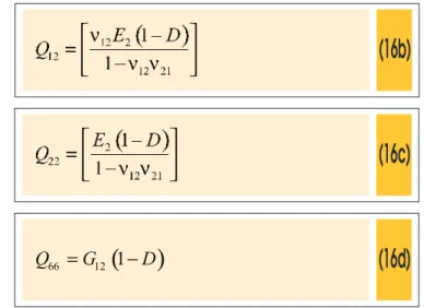
(16a)
(16b)
(16c)
(16d)
(
)
66 12
1
Q
=
G
-
D
where: 1
E
is the longitudinal elastic modulus in directionx
;2
E
is the longitudinal elastic modulus in directiony
;12
υ
=υ
21 is the major Poisson´s ratio of layer associates to direc -tionsx
andy
;12
G
is the shear modulus associates to directionsx
andy
;D
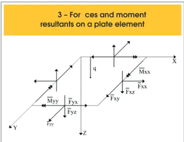
represents the damage of material.In this formulation, the loads and moments can be expressed in matrix form as (Figure 2):
(17a)
(17b)
where
N
xx,
N
yy andN
xy are in plane membrane forces per unitlength (due to stretching of the plate mid surface),
M
xx andM
yyare bending moments per unit length about the
y
andx
axes, respectively, andM
xy are twisting moment per unit length (similarto torsion in a beam).
These matrices are termed:
A
ij = extensional stiffness matrix;D
ij= bending stiffness matrix;
B
ij = extension-bending coupling ma-trix. A convenient form for the
[ ]
A
,[ ]
B
and[ ]
D
matrices can beestablished by examining the position of the
k
th lamina in Figure 2:(18a)
( )
(
)
1 1n k
ij ij k k
k
A
Q
z
+z dz
=
=
å
-(18b)
(18c)
( )
(
( )
3 3)
1 11
3
n kij ij k k
k
D
Q
z
+z dz
=
=
å
-Can be observed in equation 17 that internal forces and moments are dependent of displacements, layer position and material prop
-erties. Therefore, the application of nonlinear models (damage model of concrete and plasticity of steel) affect directly the me
-chanical behavior of laminated plates.
The virtual work done by internal forces is expressed by:
(19)
0
2
0 0 0 0 0
2
int xx yy xy xx
r
u
v
u
v
w
W
N
N
N
M
x
y
y
x
x
d
=
ï
í
ì
d
è ø
ç ÷
æ ö
+
d
æ ö
ç ÷
+
é
ê
d
æ ö
ç ÷
+
d
ç ÷
è ø
æ ö
ú
ù
-
d
ç
æ
ö
÷
-
è ø
è ø
è
ø
ï
ë
û
î
ò
2 2 0 0 22
yy xyw
w
M
M
dxdy
y
x y
d
æ
ö
d
æ
¶ ï
ö
ü
-
ç
÷
-
ç
÷
ý
¶ 
è
ø
è
øïþ
where
r
0 is the area of the mid-surface of the plate.The virtual work done by external forces can be expressed by Eq. (20) considering loads acting on the domain and on the boundary of the plate (Figure 3 shows positive directions of loads) and ac
-cording assumption 7:
(20)
which
is the transversal force per unit area acting on mid-surface of the plate;
xx
F
,F
xy andF
xz are the forces per length unit along the edges0
x
=
andx
=
a
, second to the directionsx
,y
ez
, respectively;xx
M
is the bending moment per unit length, applied along the edg -esx
=
0
andx
=
a
;yx
F
,F
yy andF
yz are the forces per length unit along the edges0
y
=
andy
=
b
, according to the directionsx
,y
ez
, respectively;yy is the Bending moment per unit length applied along the edg
-es
y
=
0
andy
=
b
.The moment of torsion was not considered in the external work since it is not usually applied in slabs, despite it appears the inter
-nal efforts.
3. Numerical formulation
After expressing the work done by internal forces as a function of displacement, by replacing the expressions of internal efforts (17a) and (17b) in (19), the numerical treatment according to EFDM can
be applied.
First, it is necessary to introduce in equations of the
δ
W
int and extW
δ
the representations used in inite differences for the deriv-atives of the displacements. It is assumed, for evaluation these virtual works, that the plate is divided into sections of integration (area elements) in which all magnitudes involved are supposed constant. After determination of
δ
W
int eδ
W
ext, by the summationof the contributions of the various sections of integration, a system of algebraic equations of equilibrium is obtained by application of principle of virtual work. The resolution of this system permits to
obtain the numerical solution based in unknowns nodal displace-ments
u
0,v
0 ew
0. To determination of the system of algebraic equations it is considered the kinematic condition of the boundary and others variation of displacements, arbitrary and independent of each other.In the numerical formulation developed in this work are used two types of representations for the derivatives of the displace -ments: centered representation and reduced representation.
For this, consider the Figure 4, where
f x
( )
represents thefunction
u
0,v
0 ew
0 andm
is the point where the derivativesare evaluated (pivotal point). The nodal spacing is λ. First and second derivative of the function
f x
( )
evaluated at pointm
are
(
)
1 1
1 '
2
m m m
f f f
λ + −
= − and "
(
)
1 1
2
1 2
m m m m
f f f f
λ + −
= − + .
Figur
3 – For ces and moment
e
In areas located along the edges of the board, the use of rep
-resentation centered at the irst derivative of
u
0 andv
0 cancause singularity in the coeficient matrix. Therefore, for those derivatives is assumed to reduced representation, as sug
-gested by Graça [14]. This representation can be deined by
(
1)
1
'm m m
f f f
λ +
= − .
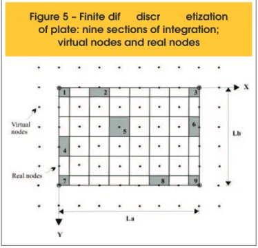
For the numerical discretization of the domain
L
a×
L
b of plate, themethod provides a generation of sections of integration obtained from subdivisions in the
x
andy
directions:n
x andn
y,respec-tively. Thus, an generic section of integration presents the rect
-angular dimensions
λ
x/
=
L
an
x andλ
y/
=
L
bn
y, with a total of(
n
x+
3
)
×
(
n
y+
3
)
nodes and(
n
x+
1
)
×
(
n
y+
1
)
area elements for integration, with nine different types of section, as shown in Figure 5. The area element type 1, 3, 7 and 9 are located in the corners of the plate and display area4
x y
λ
×
λ
, while the element type 2, 4, 6and 8, the area is
2
x y
λ
×
λ
. The remaining sections of integration(type 5) have area
λ
x×
λ
y, as illustrated in Figure 5.The section of integration (see Figure 5) is composed of nine nodal points and for each of these points are associated with three de
-grees of freedom
u
0,v
0 andw
0, which incorporates, for each areaelement a total of 27 displacements. Note that the second-order derivatives of the displacements of the nodes, associated with the edges of the board, require external nodes, called virtual nodes. More information about the sequence of development of the nu
-merical treatment, according to EFDM, can be found in [13-15].
4. Comparisons with experimental results
Two slabs solved in the literature was resolved by the aid of the newly developed computer program: a two-way slab support
-ed by its four -edges and submitt-ed to distribut-ed loading [27]; a two-way slab supported by its four corner and submitted to
Figura 4 – Function f (x) used to represent
the derivative of displacement
fer ence
discr
etization
of plate: nine sections of integration;
virtual nodes and real nodes
Table 1 – Material properties
Slab supported by its four edges
E(GPa) v
c fc (MPa) Ac Bc ft (MPa) εd0 At Bt fy (MPa)
Concrete steel
32,42 0,18 35,04 1,00 1600 3,60 1,11 x 10⁻⁴ 0,80 10000 –
206,91 – – – – – – – – 375,90
Slab supported by its four corners
E(GPa) v
c fc (MPa) Ac Bc ft (MPa) εd0 At Bt fy (MPa)
Concrete steel
28,61 0,15 37,92 1,00 1650 3,80 1,33 x 10⁻⁴ 0,80 10000 –
concentrated load [28]. The numerical discretization used the ge
-ometry and loading symmetry, analyzing thus, a quarter of plate. The numerical results were compared with experimental load-de
-lection curves of slabs and rupture load.
4.1 Computer simulation of stress–strain curves
Table 1 shows the experimental dates of used concrete (
E
c,f
c, tf
eυ
c) and steel (E
s ef
y) and the parameter values associated with damage model. Based on dates, the theoretical stress-strain curves (Figure 6) were obtained using equations (10) and (11). Initially, the strain value tdo
f
E
ε
=
was determined. After this,appropriate constants
A
t,B
t,A
c andB
c.are tested until to obtaina good agreement between experimental and theoretical values.
The obtained tensile parameter
A
t shown similarity with valuesindicated by Lemaitre e Mazars [34] and Challamel [35]. How the experimental stress-strain curves were not obtained by authors, the compressive parameters
A
c andB
c were changed until toobtain a same experimental compressive strength
f
c and a peakstrain between 2‰ and 3‰. Similar procedure was used by many researchers [18, 19, 23, 25, 34, 36].
Reinforcing steel was modeled as an uniaxial layer considered as an one-dimensional material in the reinforcement direction. The center of steel layer coincides with reinforcement center of experi
-mental slabs and has an equivalent area. An elastoplastic model was used and three parameters are necessary as input data to deine the steel model: the initial Young´s modulus
E
s, the yieldstress
f
y and the ultimate strainε
su (adopted as 10‰).Figure 6 – Analytical stress-strain curves using Damage Model of Mazars
4.2 Two-way slab supported by its four edges
Figure 7 shows the geometry, structure and reinforcement characteristics of RC-slab experimented by Taylor et al [27]. The slab, supported by its four edges and subjected to a distributed load at the top, has a square shape with 915 mm side length and 51 mm thickness.
One very important feature of non-linear models applied to the analysis of structural reinforced concrete elements is the problem of mesh size. In this example, two numerical parameters were tested. The ideal discretization was obtained after several tests and resulted in a plate with 8 x 8 subdivisions. The cross section was divided into 10, 15, 22 and 36 concrete and steel layers superimposed.
Figure 8 – Effect of damage of
transversal elastic modulus on
load-displacement behavior
The load–delection curve, calculated with 8 x 8 subdivisions and 15 layers is depicted in Fig. 8, together with the experimental re
-sults. Can be observed the presence of three numerical curves resultant of application, or not, of different damage parameter to
shear modulus
G
12:1)
( )
112
2 1
E
G
u
=
+
, where
E
1=
E
cand
u u
=
c;
2)
( )
1 12
1
2 1
c
E
D
G
u
-=
+
,
where
E E
1=
c,
u u
=
cand
D
c=
a
tD
ct+
a
D
c cc;
3)
( )
1 12
1
2 1
t ct
E
D
G
a
u
-=
+
, where
E
1=
E
cand
u u
=
c.
It was observed a great inluence of variation of transversal modu
-lus on load-delection behaviour of slabs. The adoption of undam
-aged modulus (situation 1) results in the more stiffness solution where the loss of load after the concrete cracking cannot to be ad
-equately modeled. However, the application of damage coeficient The results illustrated in Fig. 19 indicate in a numerical curve with lower stiffness, after cracking, than experimental curve. In fact, the main factor that affect the loss of transversal stiffness of concrete is the cracking of slab in region under traction. In situation 3 the isotropic damage of
G
12 is associated with theD
ct parameter anda best agreement between experimental and numerical results is observed. The fail of slab was characterized by yielding of steel of reinforcement (
å
ε
ss>
10‰
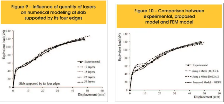
).In order to study the inluence of layer, the example was analyzed by three other meshes, composed of 10, 22 and 36 layers for the cross section. The results illustrated in Fig. 12 indicate, for the pre
-sented example, that the increasing of the number of layers from 15 to 36 produced almost the same results for the load-displace
-ment curve. So, it is important to point out that 15 layers for the cross section is really enough, even when the non-linearity effects are very signiicant.
The load–delection relationship obtained by this model is again shown in Fig. 10 in addition to results presented by Jiang e Mirza
Figure 9 – Influence of quantity of layers
on numerical modeling at slab
supported by its four edges
Figure 10 – Comparison between
experimental, proposed
[16]. This last model is based in Finite Element Method, Plastic Model to concrete and Classic Theory of Plates. The obtained re
-sults are very close to the numerical ones, showing the good ac
-curacy of the present model with a similar degree of freedom.
4.3 Two-way slab supported by its four corners
The second example examined (tested by McNeice [28]) consisted of square corner-supported slab subjected to a point load applied at the center. The two-way slab was 915x915 mm square and 44 mm thick, and reinforced with an orthogonal mesh giving a rein
-forcement ratio of 0.85%. Geometric properties, rein-forcement and material parameters are shown in Fig. 11. Material parameters are shown in Table 1. The transversal modulus was damage according situation 3 indicated in the last item.
In representing this specimen, a 14 x 14 subdivision (15 x 15 area elements) was used to model one-quarter of the slab. This exam
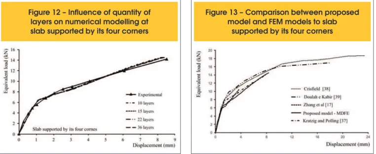
-ple also was analyzed by meshes composed of 10, 15, 22 and 36 layers for the cross section. The results illustrated in Fig. 12
Figure 11 – Geometry and structure of slab supported by its four corners according to [37]
Figure 12 – Influence of quantity of
layers on numerical modelling at
slab supported by its four corners
Figure 13 – Comparison between proposed
model and FEM models to slab
supported by its four corners
indicate reasonably accurate predictions of load-delection curve and they conirm the use of 15 layers as the better solution. The modiication of stiffness, after cracking of concrete, is resultant of numerical application of damage to concrete. In ultimate load it is veriied a large concrete strain (
ε
c>
5.7‰
) and a steel strain inelastic regime (
ε
s<
10‰
) that indicate a rupture of slab by crush-ing of concrete under compression.
The McNiece slab is one often used as a benchmark for calibrating nonlinear analyses. Comparison of present model with another numerical model are shown in Figure 13. Kratz e Polling [37] used elastoplastic damage model to represent the stress-strain behav
-ior of concrete under tension and compression in a Finite Element Method (FEM) program. Crisield [38] evaluated the combination of FEM, using square elements, with linear softening behavior of concrete under traction. The criterion of Von Mises was ad
-ear curve in compression. Zhang et al [17] used FEM (square element with 24 degrees of freedom) associated with Classic Theory of Plates of Mindlin and Reissner. Concrete was modeled as elastic linear under compression and to the tensile behavior
under traction was used a new model that consider the
crack-ing of concrete in orthogonal direction with main direction. It is observed a better agreement with Krazt and Polling model while another models shown a more stiffness solution after irst crack and rupture load very different of the experimental results. Thus the damage model appears as a good alternative for modeling concrete behavior.
5. Conclusion
A new model was presented in this work to predict the lexural behavior of reinforced concrete slabs. Combining the Finite Dif
-ference Energy Method with Classical Theory of Laminates it was possible to perform a nonlinear analyses by application of Damage Model, proposed by Mazars, to represent the concrete behavior
under tracion and compression.
The results indicate the necessity of the application of tensile dam
-age parameter (
D
ct) to reduces the transversal elastic modulusafter cracking of concrete. In fact, how the evaluation of reinforced concrete slab is a bidimensional problem, the cracking affect the
properties in all directions.
The comparison with experimental results demonstrate the efi
-ciency of method to describe the load-delection behavior and to determine the rupture load. Comparing with other numerical solu
-tions, using FEM, it is observed a higher accuracy of proposed model, mainly considering the low discretization necessary.
6. Aknowledgements
The authors would like to thank the CNPq and FAPESB (PPP 010/2010) and CAPES for inancial support.
7. References
[01] KURRER K-E., RAMM, E. The History of the Theory of Structures. From Arc Analysis to Computational Mechanics. John Wiley & Sons, 2008, 848pp.
[02] THOMÉE, V.. From inite differences to inite elements: A short history of numerical analysis of partial diferential equa
-tions. Journal of Computational and Applied Mathematics, vol. 128, 2001, p.1–54.
[03] HAGIYA, H., MORISHITA, M., ANDO, T.; TANAKA, H. MAT
-UO, K. Damage evaluation of reinforced concrete slabs sub
-jected to contact detonation loads with numerical simulation. Science and tecnhnology of energetic materials, vol. 64, n. 5, 2003, p.192-200.
[04] FERRETI, D. ;SAVOIA, M. Non-linear model for R/C tensile members strengthened by FRP-plates. Engineering Frac
-ture Mechanics, vol. 70, 2003, p.1069–1083.
[05] HABIB, A.; MOHARRAMI,H. Nonlinear sensitivity analysis of reinforced concrete frames, Finite Elements in Analysis and Design, vol. 46, 2010, p. 571–584.
[06] VIRDI, K. S. Finite difference method for nonlinear analysis of structures, Journal of Constructional Steel Research, vol. 62, 2006, p. 1210–1218.
[07] JONES, J., C. WUA,, D.J. OEHLERS , A.S. WHITTAKER , W. SUN, S. MARKS, R. COPPOLA. Finite difference analy
-sis of simply supported RC slabs for blast loadings. Engi
-neering Structures, vol. 31, 2009, p.2825-2832.
[08] HOUBOLT, J.C. A Study of Several Aerothermoelastic Problems of Aircraft Structures in High-Speed Flight. Zu
-rich, 1958, Doctoral Thesis - The Swiss Federal Institute of Technology.
[09] GRIFFIN, D. S.; VARGA, R.S. Numerical solution of plane elasticity problems. Journal of Society of Industrial Applied Mathematic, vol. 11, n. 4, 1963.
[10] BUSHNELL, D. Finite-difference energy models versus inite-element models- Two variational approaches in one computer program. Numerical and computer methods in structural mechanics.(A 74-17756 06-32) New York, Aca
-demic Press, Inc., 1973, p. 291-336
[11] PLETZ, E. Análise de estrutura laminares pelo método da energia discretizada. Rio de Janeiro, 1983, Tese (Mestrado) - Universidade Federal do Rio de Janeiro.
[12] NISHIKAVA, L. K. Análise numérica de placas com cantos reentrantes. Rio de Janeiro, 1991, Tese (Mestrado) - Univer
-sidade Federal do Rio de Janeiro.
[13] GRAÇA, M. S. B. A. Método das diferenças initas energé
-ticas na análise estática e dinâmica de placas delgadas e espessas, Rio de Janeiro, 2000, Tese (Doutorado) - Univer
-sidade Federal do Rio de Janeiro.
[14] LIMA, J. M. F. Estudo comparativo entre formulações geo
-metricamente não lineares para a lexo-torção de hastes de paredes delgadas de seção aberta, Rio de Janeiro, 2004, Tese (Doutorado) - Universidade Federal do Rio de Janeiro. [15] NEVES, J. B; LIMA, J. M. F.; LIMA, P. R. L. Método das
Diferenças Finitas Energéticas para simulação do compor
-tamento sob lexão do concreto reforçado com ibras curtas de aço. Revista Sul-americana de Engenharia Estrutural, vol.10, n.2, 2013, p.31-55.
[16] JIANG, J.; MIRZA, F. A. Nonlinear analysis of reinforced con
-crete slabs by a discret inite element approach. Computers & Structures, vol.65, n.4, 1997, p. 585-592.
[17] ZHANG, Y. X.; BRADFORD, M. A.; GILBERT, R. I. A lay
-ered shear-lexural plate/shell element using Timoshenko beam functions for nonlinear analysis of reinforced concrete plates. Finite elements in analyses and design, vol.43, 2007; p.888-900.
[18] MAZARS, J. A Description of micro and macroscale dam
-age of concrete structures, Engineering Fracture Mechanics, vol.25, 1986; p.729-737.
[19] FERNANDES, G. R. Método dos elementos de contorno aplicado à análise não linear de placas, São Paulo, 1998, Dissertação (Mestrado) - Escola de Engenharia de São Car
-los - Universidade de São Paulo.
[20] CRESCE, S. H. Análise não-linear de pavimento de con
-creto armado pelo método de elementos de contorno, São Paulo, 2003, Tese (Doutorado) - Universidade de São Paulo. [21] BANDEIRA M. S. Análise não-linear de lajes de concreto ar
-mado pelo método dos elementos initos, Goiás, 2006, Dis
-sertação (Mestrado) - Universidade Federal de Goiás. [22] WANG, T.; HSU, T. Nonlinear inite element analysis of con
[23] ASSAN, A.E., Nonlinear analysis of reinforced concrete cylindrical shells. Computer and structures, vol. 80, 2002, p.2177–2184.
[24] HAIDO, J. BAKAR, B.H.; ABDUL-RAZZAK, A.A.; JAY
-APRAKASH, J. Dynamic response simulation for reinforced concrete slabs. Simulation Modelling Practice and Theory, vol. 18, 2010, p.696–711.
[25] SANCHES, F. J.; VENTURINI, W. S. Damage modeling of reinforced concrete beams. Advances in Engineering Soft
-ware, vol.38, 2007, p.538-546.
[26] LIMA, J.M.F.; NAGAHAMA. K.J.; LIMA, P.R.L.; SANTOS, G. J. B dos. Um modelo para análise não linear física da lexão de vigas de concreto armado. Mecânica Computacional, vol. XXIX, 2010, p.9839-9853.
[27] TAYLOR, R.; MATHER, D. R. H.; HAYES, B. Effect of the arrangement of reinforcment on the behaviour of reinforced concrete slabs. Magazine Concrete Research, vol.18, 1966, p.85-94.
[28] MCNEICE, G. M., Elastic-Plastic Bending of Plates and Slabs by the Finite Element Method, Ph. D. Thesis, London University, 1967.
[29] NOH, H.C.. Nonlinear behavior and ultimate load bearing capacity of reinforced concrete natural draught cooling tower shell. Engineering Structures, vol. 28, 2006, p. 399–410. [30] OLIVEIRA, R.S.; RAMALHO, M.A.; CORREA, M.R.S. A lay
-ered inite element for reinforced concrete beams with bond– slip effects. Cement & Concrete Composites, vol. 30, 2008, p. 245–252.
[31] GUAN, H.; COOPER, C.; LEE,, D-J. Ultimate strength analy
-sis of normal and high strength concrete wall panels with varying opening conigurations. Engineering Structures, vol. 32, 2010, p. 1341-1355.
[32] JONES, R. M. Mechanics of composite materials. Taylor & Francis Group, 1999.
[33] REDDY, J. N. Mechanics of Laminated Composite Plates and Shells: Theory and analysis. CRC, 2004.
[34] LEMAITRE, J.; MAZARS, J. Application de la théorie de l’endommagement au comportement non linéaire et à la rup
-ture du béton de struc-ture. De I’institut technique Du bati
-ment et dês travaux publics, vol.401, 1982, p.114-137. [35] CHALLAMEL, N. A variationally based nonlocal damage
model to predict diffuse microcracking evolution. Inter
-national Journal of Mechanical Sciences, vol.52, 2010, p.1783-1800.
[36] PITUBA, J. J. C. Avaliação de um modelo anisótropo de dano considerando a perda de resistência devido ao cis
-alhamento do concreto. Asociación Argentina de Mecánica Computacional, vol.29, 2010; p.5397-5410
[37] KRATZIG, W.B., AND POLLING, R. An elasto-plastic dam
-age model for reinforced concrete with minimum number of material parameters, Computers and structures, vol.82, n.15-16, 2004, p.1201-1215.
[38] CRISFIELD, M. A. Accelerated solution techniques and con
-crete cracking. Her Majesty’s Stationery Ofice, London, v. 33, pp. 585-607, 1981.