João Pedro Sequeira Lavadinho
Licenciatura em Engenharia de Micro e NanotecnologiasProduction and characterization of
thermoresponsive magnetic membranes
Dissertação para Obtenção do Grau de Mestre em Engenharia de Micro e Nanotecnologias
Orientador: Doutora Paula Isabel Pereira Soares, Investigadora
em Pós-doutoramento, DCM – FCT/UNL
Co-orientador: João Paulo Borges, Professor Associado com
Agregação, Universidade Nova de Lisboa
Júri:
Presidente: Doutor Hugo Manuel Brito Águas, Professor Associado, FCT-UNL Arguente: Doutor Jorge Alexandre Monteiro Carvalho Silva, Professor Auxiliar,
FCT-UNL
Vogal: Doutora Paula Isabel Pereira Soares, Investigadora em Pós – Doutoramento, FCT-UNL
iii Production and characterization of thermoresponsive magnetic membranes
Copyright © João Pedro Sequeira Lavadinho, Faculdade de Ciências e Tecnologia, Universidade Nova de Lisboa.
A Faculdade de Ciências e Tecnologia e a Universidade Nova de Lisboa têm o direito, perpétuo e sem limites geográficos, de arquivar e publicar esta dissertação através de exemplares impressos reproduzidos em papel ou de forma digital, ou por qualquer outro meio conhecido ou que venha a ser inventado, e de a divulgar através de repositórios científicos e de admitir a sua cópia e distribuição com objetivos educacionais ou de investigação, não comerciais, desde que seja dado crédito ao autor e editor.
v “Learning is the only thing the mind never exhausts, never fears, and never regrets.” Leonardo da Vinci
vii
Acknowledgements
Este trabalho marca o fim de mais uma jornada. Jornada essa que só foi possível com os contributos de várias pessoas.
Primeiramente agradeço ao Professor Rodrigo Martins e à Professora Elvira Fortunato pela criação do curso de Micro e Nanotecnologias, o que me permitiu desenvolver os meus conhecimentos num local tão privilegiado como o Departamento de Ciências dos Materiais da Faculdade de Ciências e Tecnologias da Universidade Nova de Lisboa.
De seguida, agradeço à minha orientadora, Doutora Paula Soares por toda a ajuda e principalmente pelas correções dos textos incompletos e por me ter dado na cabeça quando mais precisei. Agradeço também a disponibilidade que sempre teve para me orientar nos resultados e para me iluminar e guiar nos passos seguintes do trabalho.
Agradeço também ao Professor João Paulo Borges todas as mini ajudas que ia dando ao longo dos dias, por todas as críticas construtivas aos resultados e pela oportunidade de participar em actividades do laboratório de Biomateriais, nomeadamente a Ciência Viva.
Um especial agradecimento ao Ricardo, pois sem ele tinha ficado perdido nos resultados. Agradeço também pelas correções todas aos textos e por toda a ajuda no laboratório.
Quero também agradecer à Catarina Chaparro por toda a ajuda no laboratório e por todas as explicações sobre as NPs.
Agradeço Deneb Menda por todas as horas de análise de SEM, pela paciência que teve para mim e por todas as noites de diversão em que se juntou a nós. (teşekkür ederim).
Aos companheiros com quem dividi laboratório e trabalho para não ficarmos sobrecarregados e não ficarmos entediados sem ninguém para falar, David, José, Pedro, Margarida e Cezar.
Um especial agradecimento à Adriana e à Barbara por toda a ajuda e por toda a partilha de nanopartículas.
Quero também agradecer à Sofia por todas as vezes que me aturou no laboratório só porque sim e por toda a ajuda que me deu durante o curso. Os teus apontamentos salvaram-me de mais 3 anos cá!
À Íris, com acento!, por todas as conversas filosóficas sem nexo, por todas as dúvidas de química e de bio, por me teres feito rever 80% do curso para um parágrafo da tua introdução, por todos os jantares que (eu queria dizer ofereceste) trocaste e por todas as correções da tese.
À Sílvia por todas as horas que passámos a relaxar e a tentar esquecer os problemas da faculdade, pelas nossas fantásticas noites de comédia, por todas as festas em que foste a minha companhia e por todas as tardes no mininova a tentar relaxar antes do trabalho.
À minha evil twin, Chica, por todas as conversas, por todas as horas de procrastinação, todas as horas de diversão e todas as festas.
Ao Gui e ao Bolacha pelas horas no K e no Rosana em que me salvaram de conversas de maquilhagem e vestidos e por todas as noites no VII com esquemas malucos para no fim ser uma resolução básica.
Quero agradecer à Bea por todas as horas de estudo e pelos fantásticos relatórios em que davas um jeito nos meus tópicos e magicamente aparecia um texto gigante e bem escrito.
viii Também quero agradecer aos meus amigos da terrinha, que apesar de não nos vermos sempre, temos sempre tema de conversa e vontade de estar uns com os outos: Luís, Maria, Magaz, Saquete, Ana, Corado, Atípica, Jorge e Soraia.
De seguida quero agradecer a toda a OHANA por terem feito destes 6 anos os melhores da minha vida, pelos fantásticos jantares no sushi e na churrasqueira, pelas horas em festas , por toda a ajuda que me deram durante o curso e em especial durante a tese, por aqueles espetaculares traçar de capas e batismos com algo que nem eu sei o que era (e prefiro não saber), mas sobretudo por serem quem são e terem estado sempre cá.
Por último, e talvez o agradecimento mais importante, quero agradecer aos meus pais por todo o apoio e sacrifícios que fizeram para eu poder estar aqui, sei que não foi fácil. Quero ainda agradecer a minha irmã por todo o apoio que me deu ao longo destes anos.
Este trabalho foi financiado utilizando fundos concedidos pela FEDER através do Programa COMPETE 2020 e Fundos Nacionais, através da FCT – Fundação para a Ciência e Tecnologia, ao abrigo do projeto POCI – 01-0145-FEDER-007688 (Referencia UID/CTM/50025) e PTDC/CTM-CTM/30623/2017 (DREaMM).
ix
Abstract
In the last years, the electrospinning technique has proven to be very advantageous to produce polymeric membranes since it originates nanometric fibres with a high surface area/volume ratio. As a result, electrospun nanofibers have been used for different biomedical applications, particularly in the development of multifunctional devices. To increase membrane functionality additional materials such as magnetic nanoparticles (MNPs) that respond to external stimuli can be combined with electrospun fibres. The incorporation of these nanoparticles into electrospun fibres produces a multifunctional system that can be used for cancer theranostic applications.
The main objective of this work was to process a thermoresponsive polymer, polyacrylamide (PAAm), using electrospinning and to incorporate MNPs by their addition to the precursor solution. These membranes will have the ability to respond to two different external stimuli, magnetic field and temperature, being suitable for magnetic hyperthermia application.
In the first phase, an optimization study of the electrospinning parameters was made to obtain monodisperse fibres of PAAm. MNPs were synthesized by chemical precipitation technique and then stabilized with oleic acid or dimercaptosuccinic acid to avoid their aggregation. Later the MNPs were added to the precursor polymeric solution and composite membranes were produced, which were characterized in terms of its mechanical properties, and swelling ability. They were also analysed in terms of morphology, chemical properties and structurally by SEM, FTIR and XRD, respectively.
PAAm fibres with an average diameter of around 200 nm containing iron oxide nanoparticles were produced. This was confirmed by TEM and EDS analysis showing the presence of NPs and iron in the fibres, respectively. The incorporation of MNPs provided fibre reinforcement by increasing the Young’s modulus. Through magnetic hyperthermia measurements, it was possible to obtain a temperature variation of 1.1ºC, demonstrating the potential of this dual-stimuli responsive membranes for magnetic hyperthermia applications.
Keywords: Magnetic hyperthermia, superparamagnetic nanoparticles, polyacrylamide, thermoresponsive; magnetic nanocomposites.
xi
Resumo
Nos últimos anos, a técnica de eletrofiação provou ser muito vantajosa na produção de membranas poliméricas, uma vez que origina fibras nanométricas com uma elevada relação superfície/volume. Como resultado, as nanofibras electrofiadas têm sido usadas para diferentes aplicações biomédicas, particularmente no desenvolvimento de dispositivos multifuncionais. Para aumentar a funcionalidade da membrana, materiais adicionais que respondem a estímulos externos podem ser combinados com fibras electrofiadas como por exemplo nanopartículas magnéticas (MNPs). A incorporação destas nanopartículas nas fibras produz um sistema multifuncional que pode ser usado para aplicações de teragnóstico do cancro.
O principal objetivo deste trabalho foi processar um polímero com resposta térmica, a poliacrilamida (PAAm), usando eletrofiação e incorporar MNPs por adição à solução precursora. Estas membranas terão a capacidade de responder a dois estímulos externos diferentes, campo magnético e temperatura, sendo adequadas para aplicação de hipertermia magnética.
Na primeira fase, foi realizado um estudo de otimização dos parâmetros de eletrofiação para obter fibras monodispersas da PAAm. As MNPs foram sintetizadas pela técnica de precipitação química e depois estabilizados com ácido oleico ou ácido dimercaptosuccínico para evitar a sua agregação. Posteriormente, as MNPs foram adicionadas à solução polimérica precursora e foram produzidas membranas compósitas as quais foram caracterizadas em termos das suas propriedades mecânicas e capacidade de inchamento. Foram também analisadas em termos de morfologia, propriedades físico-químicas e estruturalmente por SEM, FTIR e DRX, respetivamente.
Foram produzidas fibras PAAm com um diâmetro médio de cerca de 200 nm contendo nanopartículas de óxido de ferro. Foi confirmado pelas análises de TEM e EDS, mostrando a presença de NPs e ferro nas fibras, respetivamente. A incorporação das MNPs provocou um reforço às fibras aumentando o módulo de Young. Através de medidas de hipertermia magnética, foi possível obter uma variação de temperatura de 1,1ºC, demonstrando o potencial dessas membranas com resposta a dois estímulos para aplicações de hipertermia magnética.
Palavras – chave: Hipertermia magnética; nanopartículas superparamagnéticas; poliacrilamida; resposta térmica; nanocompósitos magnéticos.
xiii
Contents
Acknowledgements ...vii Abstract ... ix Resumo ... xi List of Figures ... xvList of Tables ... xvii
1 Introduction ... 1
1.1 Thermoresponsive polymers ... 1
1.2 Electrospinning ... 2
1.3 Magnetic Nanoparticles ... 3
1.3.1 Superparamagnetic effect ... 3
1.3.2 Magnetic Hyperthermia based on MNPs ... 4
1.3.3 Magnetic composite membranes ... 5
2 Materials and Methods ... 7
2.1 Superparamagnetic Iron Oxide Nanoparticles (SPIONs)... 7
2.1.1 Synthesis ... 7 2.1.2 Characterization ... 7 2.2 Polymeric solution ... 7 2.3 Electrospinning ... 7 2.3.1 Crosslinking ... 7 2.4 Incorporation of Nanoparticles ... 8 2.5 Membrane Characterization ... 8 2.6 Swelling ... 8 2.7 Viscosity tests ... 8
3 Results and Discussion ... 9
3.1 Thermoresponsive electrospun membranes ... 9
3.1.1 Polymeric solution ... 9
3.1.2 Electrospinning parameters optimization ... 10
3.1.3 PAAm membranes crosslinking ... 13
3.2 Magnetic Nanoparticles ... 16
3.3 Magnetic Membranes characterization ... 18
xiv 3.3.2 Stress tests ... 22 3.3.3 Swelling ... 25 3.3.4 Magnetic Hyperthermia ... 26 4 Conclusion ... 29 5 References ... 31 6 Supporting Information ... 35
xv
List of Figures
Figure 1.1 - Polyacrylamide chemical structure [13]. ... 1 Figure 1.2 - Schematic illustration of the electrospinning apparatus [8]. ... 2 Figure 1.3 - Important parameters obtained from a magnetic hysteresis loop. The saturation magnetization, Ms, remaining magnetization, Mr, and coercivity, Hc [29]. ... 4
Figure 3.1 - Viscosity variation as a function of shear rate for PAAm solutions in water with different polymer concentrations (w/w) (For most values the standard deviation is negligible and is represented where it does not.). ... 9
Figure 3.2 - Viscosity variation as a function of polymer concentration in solutions for a constant shear rate of 1 s-1. (For all samples, except the 6 wt.%, the standard deviation is negligible). ... 10
Figure 3.3 - SEM image for fibres produced using the following parameters 0.25 ml.h -1; 15 cm and 15 kV for the 4 wt.% PAAm solution in water and its diameters and variations (30 fibres were measured using ImageJ software). ... 12
Figure 3.4 - SEM image for fibres produced using the following parameters 0.25 ml.h -1; 15 cm and 15 kV for the 4 wt.% PAAm solution in water. ... 12
Figure 3.5 - SEM image for fibres produced according to parameters 0.25 ml.h -1; 15 cm and 15 kV for the 4 wt.% PAAm solution in water/ethanol and its diameters and variations (30 fibres were measured using ImageJ software). ... 12
Figure 3.6 - SEM image for fibres produced according to parameters 0.25 ml.h -1; 15 cm and 20 kV for the 4 wt.% PAAm solution in water/ethanol. ... 13
Figure 3.7 – Non-crosslinked polyacrylamide electrospun membrane before (left) and after (right) contact with water. ... 13
Figure 3.8 - Schematic representation of crosslinking of polymer chains (adapted from [47]). . 14 Figure 3.9 - Crosslinking reaction between PAAm and GA [17]. ... 14 Figure 3.10 - Effect of crosslink on polymeric membranes for several times: 1 h (left); 2 h (centre); 5 h (right) and at various temperatures: a) 80 °C; b) 100 °C; c) 120 °C; d) 140 °C; e) 150 °C. ... 15
Figure 3.11 - Membrane after 2 h at 80 ºC (left) and after 1 h at 120 °C (left). ... 16 Figure 3.12 - FTIR analysis for PAAm before and after crosslinking reaction with glutaraldehyde. ... 16 Figure 3.13 - XRD diffractogram of pristine nanoparticles, oleic acid-coated nanoparticles and DMSA coated nanoparticles... 18
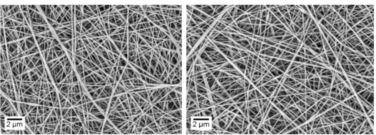
Figure 3.14 - TEM image of A) dimercaptosuccinic coated magnetite and B) oleic acid-coated magnetite nanoparticles and the respective size distribution of nanoparticles. ... 18 Figure 3.15 - SEM image of PAAm 4 wt.% in water fibres containing NPs - DMSA produced with optimized parameters (0.3 ml.h-1; 15 cm; 15 kV) and respective diameter variation (30 fibres were mediated using ImageJ software). ... 19
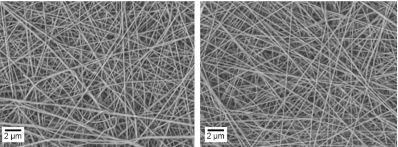
Figure 3.16 - SEM image of PAAm 4 wt.% fibres containing NPs - OA produced with optimized parameters (0.3 ml.h -1; 15 cm; 15 kV) and respective diameter variation (30 fibres were mediated using ImageJ software). ... 20
xvi Figure 3.18 - TEM images for PAAm fibres incorporating NPs - OA (left) and NPs - DMSA (right). ... 21 Figure 3.19 - FTIR analysis of composite membranes containing NPs compared to membrane of plain PAAm. ... 21
Figure 3.20 - Thermogravimetric analysis of plain PAAm membranes before and after crosslinking, composite PAAm membranes with iron oxide NPs incorporated and nanoparticles coated with DMSA and OA. ... 22
Figure 3.21- Stress curves for the different polyacrylamide membranes: 4 wt.% polyacrylamide; PAAm 4 wt.% crosslinked; PAAm 4 wt.% with NPs - OA and PAAm 4 wt.% with NPs – DMSA. ... 23
Figure 3.22 – Young’s module of each membrane type. ... 24 Figure 3.23 - Ultimate tensile strength of each membrane type. ... 24 Figure 3.24 - Swelling ratio curves of plain PAAm membranes and composite membranes at different times. Samples A) were performed at a constant temperature of 37.5 ° C. Samples B) were performed at room temperature. ... 25
Figure 3.25 - Temperature variation for DMSA and OA coated nanoparticles in suspension and composite membranes of PAAm with NPs incorporated produced using two different solvent systems: water and water/ethanol (8:2). The tests were performed for 10 min for a magnetic flux of 300 Gauss at 418.5 kHz (five tests were performed for each measure). ... 27
Figure 6.1 - SEM image of fibres produced with 4 wt.% PAAm solution in water using parameters: 0.25 ml.h -1; 15 cm and 15 kV, without humidity control (Initial humidity: 36%; Final humidity: 48%). Average diameter: 277±115 nm. ... 36
Figure 6.2 - Example of a beaded membrane produced with the 3 wt.% PAAm solution in water/ethanol, through the parameters 0.25 ml.h -1; 15 cm; 15 kV. ... 36
Figure 6.3 - Example of a beaded membrane produced with the 5 wt.% PAAm solution in water/ethanol, through the parameters 0.25 ml.h -1; 15 cm; 15 kV. ... 38
Figure 6.4 - SEM image of fibres produced by 4 wt.% PAAm solution in water using parameters 0.4 ml.h -1; 15 cm; 15 kV. ... 39
xvii
List of Tables
Table 3.1- Electrospinning conditions selected from samples obtained with a 4 wt.% PAAm solution in water and the respective mean fibre diameter and standard deviation obtained from SEM
analysis. ... 11
Table 3.2 - Electrospinning conditions selected from samples obtained with a 4 wt.% PAAm solution in water/ethanol and the respective mean fibre diameter and standard deviation obtained from SEM analysis. ... 11
Table 6.1 - Results of parameter combinations tested in the electrospinning technique. ... 35
Table 6.2 - Parameters used for Water/Ethanol (8:2) + 3 wt.% PAAm solution. ... 35
Table 6.3 - Parameters used for Water/Ethanol (8: 2) + 4 wt.% PAAm solution. ... 37
Table 6.4 - Parameters used for Water/ Ethanol (8: 2) + 5 wt.% PAAm solution. ... 37
Table 6.5 - Parameters used for Water + 3 wt.% PAAm solution... 38
Table 6.6 - Parameters used for Water + 4 wt.% PAAm solution... 39
xix
List of Abbreviations
DMSA Dimercaptosuccinic acid
E Young's modulus
EDS Energy Dispersive Spectroscopy
FAPLCS Self-aggregating polymeric folate-conjugated N-palmitoyl chitosan FTIR Fourier Transform Infrared spectroscopy
Hc Coercive field
HCl Hydrochloric acid
IONPs Iron Oxide Nanoparticles
LCST Lower critical solution temperature MNPs Magnetic nanoparticles
Mr Remaining magnetization MRI Magnetic Resonance Imaging Ms Saturation Magnetization
NPs Nanoparticles
NPs – OA Nanoparticles with Oleic Acid
NPs – DMSA Nanoparticles with Dimercaptosuccinic acid
OA Oleic Acid
PAAm Polyacrylamide
SEM Scanning Electron Microscopy
SPIONs Superparamagnetic iron oxide nanoparticles
Tc Currie temperature
TEM Transmission Electron Microscopy
TGA Thermogravimetric analysis
UCST Upper critical solution temperature
UV-Vis Ultraviolet - Visible
xxi
Motivation
Cancer is a disease in which a group of cells by a mutation on their DNA show uncontrolled growth, invading and destroying adjacent tissues. These cells can also travel to other areas of the body through the circulatory and lymphatic systems resulting in metastases [1].
According to the World Health Organization, cancer accounted for about 9.6 million deaths in 2018, i.e., approximately one in six deaths was due to cancer and the number of patients is expected to increase by 70 % over the next two decades. This raise is due to the increase in health risk factors that have been noted in recent years, such as smoking, poor diets and lack of physical activity. Thus, it is important that this disease can be correctly and early diagnosed to be properly treated to cure the patient or considerably prolong his life [1-2].
Most conventional treatments, such as chemotherapy and radiotherapy, are based on the use of ionizing radiation to destroy tumour tissues by killing them or make them stop their reproductive cycle. These treatments, however, often affect the surrounding tissues. Techniques that act at the cellular level rather than at the tissue level are then required [3]. An alternative treatment option is hyperthermia, which is defined by National Cancer Institute of the United States as a type of treatment in which the body tissue is exposed to high temperatures to damage and kill cancer cells or to make cancer cells more sensitive to the effects of radiation and certain anticancer drugs [4]. Typically, hyperthermia is clinically used in combination with radiotherapy or chemotherapy, thus decreasing the later side-effect through a dose reduction. The use of this technique is of great value in the treatment of cancer disease, but the biggest challenge of this technique is the localized temperature increase. The use of magnetic nanoparticles is an advantage to this problem because the heating is done by applying an alternating magnetic field to NPs located in the tumour [5]. The hyperthermia technique increases the blood flow in the tumour area which in return increases the amount of oxygen in that area. Radiotherapy, on the other hand, depends on the formation of oxygen free radicals. By combining the two techniques it is possible to receive a lower radiation dosage to achieve the same treatment result with fewer side effects [6].
Current state of the art focuses on developing new or improved cancer treatment option. One of the options is to use multifunctional devices such as dual-responsive devices. In these systems it is possible to combine multiple functions in the same device. A typical combination is the use of treatment and diagnostic moieties, producing a theragnostic device.
This Master thesis is integrated into project DREaMM (Ref. PTDC/CTMCTM/30623/2017) that aim to develop a nanofibrous system with dual-responsive capabilities. This system is based on magnetic nanoparticles incorporated in thermoresponsive microgels or nanofibers produced by electrospinning. Therefore, the main objective of this Master thesis is to produce thermosensitive polyacrylamide fibres using electrospinning technique, followed by the incorporation of Fe3O4 nanoparticles inside the nanofibers. With this architecture a dual-responsive system is produced with application in magnetic hyperthermia. For the optimization of electrospinning parameters, studies will be performed by varying one parameter at a time to obtain the finest possible fibres. For the development of the multifunctional composite system, this topic contains several sub-goals to achieve the main goal:
xxii • Production and characterization of PAAm membranes with incorporated Fe3O4
nanoparticles.
• Study of the mechanical, morphological and swelling properties of composite membranes.
• Study of magnetic hyperthermia to evaluate the viability of the composite in cancer therapy.
1
1 Introduction
1.1 Thermoresponsive polymers
Thermoresponsive polymers are a class of "smart" materials that can respond to a temperature variation. These materials are widely used in biomedical applications, such as drug delivery and tissue engineering. There are two types of thermoresponsive polymers: those that react to a decrease in temperature and have a lower critical solution temperature (LCST); and polymers that respond to a temperature increase above a certain value having an upper critical solution temperature (UCST)[7–9]. The rationale of using thermoresponsive polymers for drug delivery applications comes from the need to deliver the drugs in the right area, at the right time, and at the right concentration. Therefore by using thermoresponsive polymers for this purpose ensures that the loaded drug is only released upon trigger by an external stimulus, such as a variation of temperature [10].
In tissue engineering, thermoresponsive polymers are mainly used in two situations: as substrates that enable cell growth and proliferation, and as injectable gels. In the first, the thermal ability of the polymer is used to regulate the cells attachment and detachment from a surface. The application for the second case involves the encapsulation of cells in a three-dimensional structure. That will allow the delivery of encapsulated cells to deliver nutrients, drugs, and growth factors to defects of any shape using minimally invasive techniques [11].
Polyacrylamide (PAAm) is a biocompatible thermoresponsive polymer with an UCST around 35 ºC (close to body temperature). Above the critical temperature, polyacrylamide is completely miscible with the solvent [10]. This polymer has a linear amorphous structure (Figure 1.1) and it is water-soluble, being used both at industrial and biomedical level. This compound is a strong candidate for biomedical applications including controlled drug delivery due to the proximity of its transition temperature to the body temperature. Its use in the paper industry is also wide, as well as in water treatment and oil removal on rocks [12].
Figure 1.1 - Polyacrylamide chemical structure [13].
In biomedical uses, polyacrylamide has several advantages over other biomaterials: its stability with pH variations and its mechanical stability makes this polymer an excellent enzyme immobilizer and drug distributor. Polyacrylamide is also used to remove extracorporeal toxins, passing blood through a polyacrylamide membrane, due to their non-degradation with plasma (applicable to all blood flow) [14,15].
Polyacrylamide can be processed by electrospinning to produce thermoresponsive nanofibers for biomedical applications [16]. Lu et al. [17] produced PAAm fibres with diameters between 267 nm
2 and 2.8 µm with good thermal stability, good water affinity, good absorption rate and very good tensile strength. The membranes were capable of encapsulating b-galactosidase enzymes which allowed efficient diffusion of substrate and released products into surrounding media. Gavini et al. [18] incorporated diclofenac sodium salt into polyacrylamide hydrogels for drug delivery and performed in vitro release testing and swelling properties for different crosslink types. They concluded that the drug became more stable the lower the crosslinking degree, thus showing that this polymer can be used in drug delivery.
1.2 Electrospinning
Electrospinning is a technique that uses electrostatic forces to produce nanofibrous membranes with a diameter up to a few micrometres using a polymer solution, a collector, and a strong electric field (Figure 1.2) [19]. This allows the production of membranes with specific characteristics such as controlled porosity and high surface-to-volume ratio [20]. The setup includes a spinneret, a high voltage supply (usually one that provides continuous current), a grounded collector, and a syringe with a desired solution connected to a syringe pump. In this setup, because the metallic rim and needle are connected to the electrode, and the collector is grounded, an electromagnetic field is formed by the difference in potential between the needle and collector being this field uniformized by the rim. Electrostatic forces are formed, and the positive charges gather in the solution droplet at the tip of the needle. Then, due to an excess of positive charges, they repel one another such that it comes to a point where the electrostatic forces surpass surface tension and the droplet is stretched [19]. This allows the production of membranes with specific characteristics such as high surface-to-volume ratio [20]. As the jet goes from the needle to the collector, due to the vapour pressure, the solvents of the solution will evaporate and only the polymer will remain in the fibre. The polymer thread will then reach the collector and be deposited upon it. After some time, the fibres overlap, and a membrane is produced. The membrane is then removed from the collector, and, if there are remnants of solvent in it, it will dry. Other processes such as cross-linking and other alterations to the membrane can be made as well [14, 16].
3 Electrospinning parameters can be exploited to tailor the type of fibres desired. Some of the parameters are temperature, humidity, voltage, the distance between the needle and the collector, concentration of polymer in the solution, type of solvent, type of collector, needle gauge, flow rate [9].
Since electrospinning technique was discovered, many polymers have been used and for various uses, such as tissue regeneration or the production of metal nanofibers for use in solar cells or even as reinforcement of other structural materials [21]. Nowadays, many different types of biomolecules have been incorporated into scaffolds of electrospun nanofibers [21].
1.3 Magnetic Nanoparticles
Magnetic nanoparticles can be characterized as a type of nanomaterial able to respond to a magnetic field. These nanoparticles can be applied in industrial [22] and environmental catalysis [23], magnetic resonance imaging [24], biomedicine [22], data storage [25], micro and nanofluidic [26], etc. They become especially important in the medical field, where they can be used as contrast agents in magnetic resonance imaging, controlled drug delivery and tumour therapy through magnetic hyperthermia treatments [4]. Rudakov et al. [27] encapsulated SPIONs into carbon nanocages, creating a material with high saturation magnetization showing that the composite has applications in various areas such as drug delivery, superconductors, etc.
Xiao at al. [28] developed a new method of magnetic resonance imaging with iron oxide nanoparticles incorporated into N-palmitoyl chitosan micelles. Its tumour targeting ability has been demonstrated in vitro and in vivo. The study indicates that self-aggregating polymeric folate-conjugated N-palmitoyl chitosan (FAPLCS)/SPION micelles can potentially serve as safe and effective Magnetic Resonance Imaging (MRI) contrast agents for detecting tumours that overexpress folate receptors.
Magnetic iron oxide nanoparticles ranging in size from 1 - 100 nm can be easily manipulated through an external magnetic field and subsequently used for cancer treatments. However, due to their oxidation, they must be coated to prevent the changes in oxidation states, and thus, the chemical stability of the particles. This coating allows their incorporation into the fibres produced by the electrospinning technique [27].
1.3.1 Superparamagnetic effect
One of the types of magnetism in materials is superparamagnetism, which usually occurs in iron oxide nanoparticles below a critical size. Figure 1.3 shows the hysteresis cycle (magnetization vs field) of a magnetic material. The application of a sufficiently large magnetic field causes a rearrangement in the spins that align with the field. The maximum magnetization value achieved is called saturation magnetization, Ms. As the field magnitude decreases the spins stop aligning with the field and the total magnetization decreases. The magnetization value when the field is null is called the remaining magnetization, Mr. The coercive field, Hc, is the magnitude of the field that must be applied in the opposite direction to bring the magnetization of the sample back to zero [29].
4
Figure 1.3 - Important parameters obtained from a magnetic hysteresis loop. The saturation magnetization, Ms, remaining magnetization, Mr, and coercivity, Hc [29].
Below a critical diameter (Dc) of a few dozen nanometres, the formation of multiple domains is energetically unfavourable. For this reason, below Dc the particles have only one domain, so the change of magnetization will occur through the spins giving greater coercivities. The smaller the particle, the more spins will be affected by thermal fluctuations and the system becomes superparamagnetic. In addition to size, temperature must also be higher than a specific temperature called lockout temperature, TB, defined by Eq 1.1:
𝐾 = 25 𝑘𝐵 𝑇𝐵
𝑉 Eq. 1.1
Where K is the magnetic anisotropy constant, kB is the Boltzmann constant and V the volume of a single nanoparticle. [9-10].
1.3.2 Magnetic Hyperthermia based on MNPs
Magnetic hyperthermia is a treatment technique in which heat is used as a therapeutic agent. This type of treatment consists of raising the temperature of the cancerous tissue above a therapeutic value, usually 42.5 °C, keeping the tissues adjacent to the tumour below the temperature that may cause pain, or even be detrimental to their functioning. This is possible due to the higher sensitivity that tumour cells have to temperature relative to healthy cells.
Hyperthermia treatments have been used for several years to treat cancer. Hippocrates treated tumours by cauterization with a hot iron. More recently MNPs such as magnetite have been used for the practice of hyperthermia due to their non-toxicity, their biocompatibility and the fact that they increase the temperature in the presence of alternating magnetic fields [10 - 11].
Magnetic hyperthermia involves the localized application of MNPs and the application of an external magnetic field that will lead to heat generation by the NPs. This magnetic field has the advantage of not being absorbed by the tissues, allowing deep penetration into them [4]. There are two ways for NPs to generate heat from an alternating magnetic field: through Néel and Brownian relaxations. The first case is due to the internal rotation of the particle's internal dipole, while the second
5 case refers to the physical rotation of the nanoparticle [31]. In the superparamagnetic state, the magnetic moments of the NPs fluctuate around a magnetization axis, so each of the magnetic nanoparticles (MNPs) will have a high magnetic moment that continuously changes its direction. When applying a magnetic field, MNPs have a rapid response to field variations with no remnant magnetization or coercivity. It can then be said that in this state an MNP behaves like an atom with a giant spin [32].
The first time this technique was used was in 1957 by Gilchrist et.al. [33]. In this study, iron oxide nanoparticles were injected in the intestinal wall of dogs with the expectation that the particles would accumulate in regional lymph nodes. These nodes were dissected and exposed to an alternating magnetic field with 1.6 – 2 kA/m and a frequency of 1.2 MHz and it was verified that the temperature raised 14 ºC in 3 minutes, verifying both the presence of the NP and the heating of those particles when exposed to the magnetic field.
Murakami et al. [34] incorporated magnetite nanoparticles into hydroxyapatite for use in bone cancer hyperthermia treatments, achieving very promising results in the use of this technique.
1.3.3 Magnetic composite membranes
Magnetic polymer composites represent a type of functional materials in which magnetic nanoparticles are inserted into the polymeric structure. In recent years they have attracted a lot of interest due to their potential in applications such as cell separation, medical diagnostics, drug delivery, high data storage capacity, among others [35].
Wang et al. [36] used poly(acrylic acid)-coated magnetic particles in a polyethylene oxide suspension and a polyvinyl alcohol coating in electrospinning. The produced fibres showed superparamagnetic properties, showing deflection when exposed to a magnetic field. The extent of this deflection was correlated with the strength of the magnetic field. In a similar study, Gupta et al. [37] used MnZnFe-Ni superparamagnetic particles in a segmented polyester-based polyurethane (Estane). The produced fibres showed superparamagnetic behaviour with no remnant magnetization.
Sasikala et al. [38] created a new magnetic fibre for endoscopic hyperthermia treatments and localized drug delivery. using iron oxide nanoparticles (IONPs) as a drug distributor and bortezomib as a pharmaceutical agent. The fibres were made by electrospinning the poly(lactic-co-glycolic acid) (PLGA) polymer and dopamine-conjugated NPs for bortezomib aggregation. The device has shown very promising results in the treatment of intravenous cancers.
Matos [31] incorporated SPIONs into cellulose acetate fibres for magnetic hyperthermia applications producing membranes with embedded NPs, obtaining variations of about 0.6 ºC for low concentrations of NPs and showing that the used composite does not present cytotoxicity.
As shown by these examples, the combination of smart materials, electrospinning and magnetic properties of some particles can lead to the development of new and versatile systems that allow the use of magnetic hyperthermia in a system that can be activated at a certain temperature, being then “switched” on whenever necessary.
7
2 Materials and Methods
2.1 Superparamagnetic Iron Oxide Nanoparticles (SPIONs)
2.1.1 Synthesis
Iron oxide nanoparticles were synthesized by chemical co-precipitation using an adapted method from Soares et al. [39]. Ferrous and ferric chlorides FeCl3.6H2O: 5 mmol and FeCl2.4H2O: 2,5 mmol (Alfa Aesar and Sigma-Aldrich, respectively) were each dissolved in 50 ml of ultrapure (Milli – Q) water and mechanically stirred. 10 ml of 25 % ammonia (Sigma – Aldrich) solution was added to the mixture and allowed to stir for 5 min. Finally, 60 ml of ultrapure water was added to stop the reaction.
The iron content in the iron oxide nanoparticles was determined using the 1,10-phenanthroline colourimetric method [39,40]. The nanoparticles were stabilized with oleic acid (OA) (Panreac) and dimercaptosuccinic acid (DMSA) (Acros organics 98%). After the addiction, both solutions were left to react in an ultrasonic bath for 3 h. The solutions were left on dialysis until reaching a pH of 7.
2.1.2 Characterization
The X-ray diffraction analysis was performed at room temperature using an X’Pert PRO PANAlytical X-ray powder diffractometer (Cu K-alpha radiation) operating at a voltage of 45 kV, with an angle range between 15º and 80º and a step size of 0.033º.
Fourier transform infrared (FTIR) spectroscopy was performed using a FTIR spectrometer (Thermo Nicolet 6700) in the wavenumber range 4000– 500 cm-1.
The morphological evaluation of the nanoparticles was assessed using a transmission electron microscope (TEM) (Hitachi H-8100 II with LaB6 thermionic emission and 2.7 Å peer resolution)
2.2 Polymeric solution
Two solvent systems were used for the precursor solutions: ultrapure water (Mili-Q), and ultrapure water/ethanol (Sigma-Aldrich) in a ratio (8:2) (w/w). Various quantities of polyacrylamide (BDH laboratory reagents) were tested: 2 %, 3 %, 4 %, 5 % and 6 % (w/w). All solutions were stirred overnight
.
2.3 Electrospinning
For all the solutions described above, 1 ml of each was transferred to a 1 ml syringe (Braun, Bad Arolsen, Germany) with a 27 G needle and electrospun with different parameters. The voltage was varied between 15 and 20 kV using a Glassman EL 30 kV source. The flow rate was between 0.15 and 0.25 ml.h -1 using a KDS100 – KD Scientific pump, and the distance between 15 and 20 cm. For all samples, the temperature was kept below 30 °C and the humidity below 35 %.
2.3.1 Crosslinking
As the polymer used is water-soluble, it is necessary to crosslink the resulting fibrous membranes. For this, an adaptation of the procedure of Lu et al. was used [17]. PAAm membranes were immersed in a glutaraldehyde (GA) solution. 10 wt.% of 50 % aqueous GA (Sigma-Aldrich) and 4 wt.% of hydrochloric acid (HCl) 37 % (v/v) were diluted in ethanol 99.99 % (Sigma-Aldrich). Each membrane was placed between two glasses to prevent shrinking and heated for 2 h at 80 ºC. The
8 membranes were washed in ethanol to remove the residual GA and left for 24 h in water to remove residual HCl and hydrate for better handling.
2.4 Incorporation of Nanoparticles
For the preparation of the magnetic membranes, nanoparticles were added directly to the precursor solution in a ratio of 2 wt.% to the polymer mass used. An electrospinning technique flow rate adjustment was required.
2.5 Membrane Characterization
Fibre morphology and diameters were analysed by scanning electron microscopy (SEM) analysis using the Carl Zeiss Auriga SEM equipment. The samples were coated with gold and palladium and were placed under vacuum in the apparatus. Backscattering electrons were used at an acceleration voltage of 15 kV. With an energy dispersive spectroscopy (EDS) analysis performed by an equipment coupled with Sem belonging to Oxford Instruments EDS.
To evaluate the young’s Modulus, the samples were cut into rectangles with dimensions of 20 x 10 mm and the thickness measured with a digital micrometre (Mitutoyo 0 - 25 mm). The assays were performed on a 20 N load cell Rheometric Scientific uniaxial machine operable with the "Minimat" software (Minimat Control Software Version 1.60 February 1994 (c) P.L. Thermal Science 1984-94 Rheometric Scientific Ltd.). A velocity of 1 mm.min -1 was applied.
The X-ray diffraction analysis was performed at room temperature using a X’Pert PRO PANAlytical X-ray powder diffractometer (Cu K-alpha radiation) operating at a voltage of 45 kV, with an angle range of 15° to 80° and a step size of 0.033.
The mass loss according to the temperature variation was evaluated by thermogravimetric analysis using the NETZSCH STA 449F3 equipment, in a range of 25 to 400 ºC for 10 min with nitrogen flow alone.
To evaluate the thermal behaviour of the membranes, the equipment NanoScale Biomagnetics, DM100 Series was used for 10 min with a magnetic flux density of 300 Gauss and a frequency of 418,5 kHz.
To evaluate the presence of NPs in the fibres, the same TEM parameters were used for the morphology of the NPs.
2.6 Swelling
The swelling was performed with phosphate buffer solution (PBS) at 5, 10, 30 min and 1, 2 and 4 h at 37 ºC with mechanical agitation and at room temperature. Samples were weighed before and after dipping to assess mass variation.
2.7 Viscosity tests
Viscosity tests for all of the above solutions were performed on a HAAKE MK500 rheometer ranging from 1 to 512 rpm. All tests were performed at room temperature (approx. 25 °C).
9
3 Results and Discussion
3.1 Thermoresponsive electrospun membranes
3.1.1 Polymeric solution
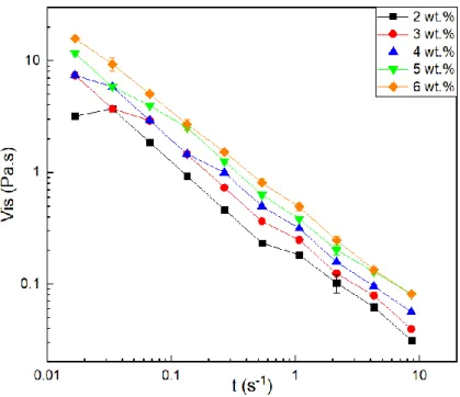
The viscosity of the precursor solution is one of the most important parameters in the electrospinning technique. On one hand, very low viscosity does not produce continuous or soft fibres; on the other hand, very high viscosity results in difficult jet ejection forming a droplet on the needle tip [9]. In order to assess the change in viscosity over time as a function of the effect of increasing polymer concentration in the solution, viscosity tests were performed at different shear rates. To assess the viscosity of the solutions according to the polymer concentration, various PAAm solutions in water were prepared by varying the amount of polymer to obtain solutions with concentrations of 2 %, 3 %, 4 %, 5 % and 6 % (w/w). This is represented in Figure 3.1 where it can be seen that viscosity increases with increasing concentration. This result is in agreement with the results obtained by Kulicke et al. [16], where it was confirmed that for the same polymer molecular weight, an increase in the polymer concentration will make the solution more viscous at the same shear rate.
Figure 3.1 - Viscosity variation as a function of shear rate for PAAm solutions in water with different polymer concentrations (w/w) (For most values the standard deviation is negligible and is represented where it does not.).
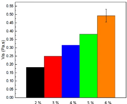
In Figure 3.2 it is represented the viscosity variation for all solutions at a shear rate of 1 s-1. With this comparison it is possible to verify a linear increase in viscosity, as expected, as the variation of polymer concentration in the solution is also linear, as expected for polyacrylamide [41].
10
Figure 3.2 - Viscosity variation as a function of polymer concentration in solutions for a constant shear rate of 1 s-1. (For all samples, except the 6 wt.%, the standard deviation is negligible).
3.1.2 Electrospinning parameters optimization
In the beginning of this thesis, a study was conducted to find the optimal parameters to electrospun polyacrylamide in order to obtain a thermoresponsive nanofibrous membrane. To study the influence of each parameter on fibre morphology, several conditions were used, varying only one factor at time for each polymer concentration in both solvents (Table 6.2, Table 6.3 and Table 6.4 for ethanol/water solvents and Table 6.5, Table 6.6 and Table 6.7 for water solvent.) The results for each parameter can be seen in Table 6.1 in supporting information but the humidity control in the electrospinning chamber was disregarded, resulting in thicker fibres due to incomplete evaporation of the solvent (Figure 6.1). The study was then restarted considering the humidity control and with same parameters. Solutions with polymer amounts of 2 and 6 wt.% did not produce fibres, due to the low and high viscosity, respectively. The 3 and 5 wt.% solutions produced fibres with beads (Figure 6.2 and Figure 6.3) when analysed under the optical microscope. The 4 wt.% PAAm solution using both water or water/ethanol as solvent produced non-defective and monodisperse fibres when observed by optical microscopy. For this reason, only fibres produced by those solutions were taken to morphological analysis through SEM and were used in this work.
Table 3.1 and Table 3.2 show the selected electrospinning conditions used to make fibres from the 4 wt.% PAAm solution using water or water/ethanol as solvent, respectively. In the same tables, it is possible to observe the combination of parameters of the two solutions, which yielded monodisperse and defect-free fibres and were taken to SEM for morphological analysis (Figure 3.3 to 3.6). The fibres were then measured using ImageJ software and the optimal parameters were selected according to the smallest mean fibre diameter and standard deviation.
By analysing the average fibre diameter of the membranes produced by the solution whose solvent was only water (Table 3.1) and also based on the surface morphology, it can be verified that there is no significant variation in the average diameters of the produced fibres. In the solution
11 containing the two solvents, it is possible to verify that for a greater distance the average diameter increases, however, by analysing the standard deviation it is possible to verify that the average fibre diameters do not significantly change.
Table 3.1- Electrospinning conditions selected from samples obtained with a 4 wt.% PAAm solution in water and the respective mean fibre diameter and standard deviation obtained from SEM analysis.
Rate (ml.h -1) Distance (cm) Voltage (kV) Temperature (ºC) Humidity (%) Diameter (nm) Standard deviation (nm) 0.2 15 15 28 32 215 58 17.5 28 32 216 92 20 24 35 239 103 0.25 15 28.4 33 201 74 17.5 29 31 212 73 20 26 35 202 42
Table 3.2 - Electrospinning conditions selected from samples obtained with a 4 wt.% PAAm solution in water/ethanol and the respective mean fibre diameter and standard deviation obtained from SEM analysis.
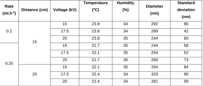
Rate (ml.h-1) Distance (cm) Voltage (kV) Temperature (ºC) Humidity (%) Diameter (nm) Standard deviation (nm) 0.2 15 15 23.9 34 292 80 17.5 23.8 34 269 42 20 23.8 35 244 60 0.25 15 21.7 35 244 58 17.5 22.1 35 254 52 20 21.7 35 260 73 20 15 22.1 35 334 84 17.5 22.4 34 333 90 20 22.4 34 281 59
Comparing the average fibre diameter of the membranes produced using different solvent systems, it can be seen that the solution containing the water/ethanol has thicker fibres. This fibre diameter increase is caused by the reduced conductivity, the increase of solution viscosity and solvent evaporation rate due to the boiling point of ethanol [42].
Figure 3.3 and Figure 3.4 shows SEM images of the PAAm membranes obtained using the following parameters 0.25 ml.h -1; 15 cm and 15 kV for the 4 wt.% PAAm solution in water. It is possible to verify that the fibres are free of defects and are dispersed randomly showing a good uniformity in the diameters, which vary between 100 and 400 nm.
Figure 3.5 and Figure 3.6 show the fibres produced from the polymeric solution with water/ethanol as well as their respective average fibre’s diameter. It is possible to verify that the fibres are scattered randomly and have no defects. It is also possible to observe a smaller variation in the diameters, which are more homogeneous and with an average value of 244 nm.
12
Figure 3.3 - SEM image for fibres produced using the following parameters 0.25 ml.h -1; 15 cm and 15 kV for the 4 wt.% PAAm solution in water and its diameters and variations (30 fibres were measured using ImageJ
software).
Figure 3.4 - SEM image for fibres produced using the following parameters 0.25 ml.h -1; 15 cm and 15 kV for the 4 wt.% PAAm solution in water.
Figure 3.5 - SEM image for fibres produced according to parameters 0.25 ml.h -1; 15 cm and 15 kV for the 4 wt.% PAAm solution in water/ethanol and its diameters and variations (30 fibres were measured using ImageJ
13
Figure 3.6 - SEM image for fibres produced according to parameters 0.25 ml.h -1; 15 cm and 20 kV for the 4 wt.% PAAm solution in water/ethanol.
As the objective is to obtain the minimum diameter possible, a flow rate of 0.25 ml.h-1, a tip-to-collector distance of 15 cm and an applied voltage of 15 kV was the set of parameters chosen for membrane production because it corresponds to the parameters where the solution with the two solvents produced smaller fibres and thus it is possible to have a term of comparison between the fibres of the two membranes.
3.1.3 PAAm membranes crosslinking
Polyacrylamide is a water-soluble polymer and the purpose of this project is to apply these membranes in physiological conditions. Therefore it is necessary to crosslink the membranes to make them solvent resistant [43]. As can be seen from Figure 3.7, a non-crosslinked PAAm membrane in contact with water forms a gel and eventually dissolves.
Figure 3.7 – Non-crosslinked polyacrylamide electrospun membrane before (left) and after (right) contact with water.
There are several methods of crosslink to polyacrylamide reported in the literature: using Gamma radiation [44], using formaldehyde [45] or using a glutaraldehyde solution in ethanol [17]. The crosslink will create covalent bonds between the polymer chains forming three-dimensional networks as shown in Figure 3.8 These links will reduce the structure's mobility and increase its mechanical properties and water-resistance [46].
14
Figure 3.8 - Schematic representation of crosslinking of polymer chains (adapted from [46]).
For this work, the crosslinking method using glutaraldehyde was chosen. Additionally, the glutaraldehyde solution was combined with temperature to evaporate ethanol and newly formed water molecules and to increase chain movements to increase reagent diffusion and to provide energy for endothermic crosslink reaction to occur. In the case of polyacrylamides, crosslinking can be either by intra or intermolecular reactions. Figure 3.9 shows the possible reactions and possible reaction products [17].
Figure 3.9 - Crosslinking reaction between PAAm and GA [17].
For membrane crosslinking optimization, various temperatures were tested during different times for reaction to occur. At temperatures below 80 °C no crosslink occurred, and the membrane dissolved and returned to gel form in contact with water. At 80 °C it appears that only after 2 h of reaction the fibrous structure was kept, while with only 1 h of reaction the fibres show deformation, being fused (Figure 3.10 a)).
15
Figure 3.10 - Effect of crosslink on polymeric membranes for several times: 1 h (left); 2 h (centre); 5 h (right) and at various temperatures: a) 80 °C; b) 100 °C; c) 120 °C; d) 140 °C; e) 150 °C.
At temperatures above 100 ºC, the membrane became rigid and yellow showing signs of degradation (Figure 3.11); however it is possible to verify that at these temperatures the fibrous structure is increasingly defined and looks similar to what it had before the crosslink happened (Figure 3.10). It was also found that higher temperatures resulted in higher shrinkage rates of the membrane due to the heat-sensitive properties of the polymer. As the main application of these membranes is their use in drug delivery, it is necessary that the membranes maintain a certain degree of mobility to adsorb a drug and not be degraded. It is also important that the membrane maintained its morphology after immersion in physiological medium. If the fibres fuse together, the membrane loses characteristics such as high porosity and high surface area. Consequently, the combination of chosen parameters was 80 ºC and 2 h, because with these parameters the membrane had a good fibrous structure and no signs of temperature degradation and did not show such a large reduction in size due to polyacrylamide crosslinking (Figure 3.11).
16
Figure 3.11 - Membrane after 2 h at 80 ºC (left) and after 1 h at 120 °C (left).
The crosslinking process will alter the chemical bonds of molecules, causing two polymer chains to bind together [47]. In order to be able to evaluate these newly formed bonds, a FTIR analysis was performed as it allows to see how the molecules are linked. The FTIR analysis of polyacrylamide before and after the crosslinking process is shown in Figure 3.12. The reaction between PAAm amide group and aldehyde from GA forms imine, which can be confirmed by the band adsorption of imine C ═ N at 1538 cm-1 in crosslinked membranes (Figure 3.12). A reduction in the C — N amide band at 1413 cm-1 is also noticeable, which is consistent with the conversion of amide to imine. The reaction between PAAm amide and GA aldehyde can occur in two ways: both GA molecule aldehydes react with 2 PAAm amide groups to create a crosslink bridge with two imine bonds, or only one aldehyde reacts with the PAAm amide group to form imine bonds, while the other aldehyde is hydrolysed to carboxylic acid. The first case can be observed by the reduction of C — N amide at 1413 cm-1 and the presence of the imine C ═ N at 1538 cm-1. The second case is confirmed by the presence of carboxylic acid at bands at 1065, 1020 and 919 cm-1 [17].
Figure 3.12 - FTIR analysis for PAAm before and after crosslinking reaction with glutaraldehyde.
3.2 Magnetic Nanoparticles
The synthesis of IONPs has been optimized in previous studies in the Department of Materials Science, so the following results are for comparison only with those data already obtained.
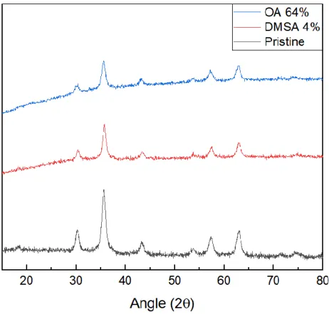
17 X-ray diffraction analysis allows to evaluate the crystalline structure of nanoparticles and to conclude about the iron oxide species present in the sample. Figure 3.13 shows the XRD diffractogram for the synthesized nanoparticles and for the NPs with their coatings. It is possible to confirm the existence of 6 characteristic peaks of iron oxide NPs for 2θ angles of: 30.1; 35.5; 43.2; 53.5; 57.0 and 62.8, corresponding respectively to the diffraction planes 220, 311, 400, 422, 511 and 440, respectively. Comparing to the standard patterns for magnetite and maghemite (reference code: JCPDS 00-0190629 for magnetite and JCPDS 00-039-1346 for maghemite), NPs have a crystal cubic structure. As magnetite and maghemite present the characteristic peaks at similar values of 2θ, the amount of magnetite relative to maghemite is verified by the difference in intensities between the peak of the plane (440) and the plane (220) and (511), which shows a higher quantity of magnetite. Another way to verify the presence of magnetite is by the similarity of intensities between the peaks of the planes 511 and 220, which is characteristic of this material. However, there is likely to be a small fraction of maghemite. The objective of having a greater amount of magnetite over maghemite is due to the superparamagnetic properties of the magnetite at room temperature, so it is necessary for the intended applications [31].
To obtain the average crystallite size, the Scherrer formula at the most intense peak (311) was used:
𝜏 = 𝐾𝜆
𝛽cos (𝜃) Eq. 3.1
Where K represents a particle shape constant (0.94), 𝜆 is the wavelength of the incident radiation (1.54 Å for Cu), β is the full width at half maximum of the highest intensity, in radians, and θ represents the value. of the angle, in radians, of the peak. From the formula it is possible to calculate a value of 9.5 nm for crystallite.
For magnetite to exhibit superparamagnetic properties at room temperature, particle sizes must be less than 20 nm [4], it is then possible to infer that the nanoparticles exhibit superparamagnetic behaviour at room temperature.
Also, from the analysis of Figure 3.13, it is possible to verify that the addition of the stabilizers does not affect the crystalline structure of the NPs, visible through the non-alteration of the diffractograms. The mean size of the stabilized NPs was also calculated by Eq 3.1, maintaining the value obtained for the crystallite, which once again confirms the non-alteration of the crystallographic structure of the particles [4,31].
Due to the very small size of the NPs, transmission electron microscopic analysis (TEM) was required, thus allowing to verify not only the morphology but also the presence of aggregates of NPs. The morphology, as well as the average diameters, of the DMSA and OA coated NPs are shown in Figure 3.14 respectively. It can be confirmed that the measured diameters for the coated NPs are very similar to the value calculated by the XRD diffractogram, thus showing that each nanoparticle is composed of only one magnetic domain. It is also possible to confirm that the surfactants used did not change the shape of the NPs, presenting an almost spherical shape and with small size variations. However, even though they are dispersed, it is possible to verify some aggregates due to interactions between particles. This can be confirmed by XRD and TEM analysis, where an average size of approximately 10 nm was determined.
18
Figure 3.13 - XRD diffractogram of pristine nanoparticles, oleic acid-coated nanoparticles and DMSA coated nanoparticles.
Figure 3.14 - TEM image of A) dimercaptosuccinic acid-coated magnetite and B) oleic acid-coated magnetite nanoparticles and the respective size distribution of nanoparticles.
3.3 Magnetic Membranes characterization
After optimizing the electrospinning parameters to electrospun plain PAAm, nanoparticles were incorporated in the electrospinning solution at a ratio of 2 wt.% of polymer’s mass. Both polymeric
19 solutions containing OA or DMSA coated NPs were homogeneous, however, the later showed the presence of some nanoparticle aggregates.
Since NPs are in aqueous solution, their addition to the precursor solutions will change their viscosity, requiring a change in electrospinning parameters. Based on the parameters used to produce the membranes with only the PAAm solution, the same study mentioned above was performed, obtaining the optimal parameters: 0.3 ml.h -1; 15 cm; 15 kV; temperature below 33 °C and humidity below 35 %. In order to evaluate the effect that the addition of NPs had on the fibres, the membranes produced with DMSA and OA NPs containing solutions were observed using SEM analysis. Membrane morphology, as well as diameter variation, can be assessed in Figure 3.15 and Figure 3.16. It can be confirmed that the incorporation of IONPs did not affect the mean fibre diameter comparing to those produced containing only the polymer, obtaining an average fibre diameter of about 200 nm. It is also possible to verify that the incorporation of the NPs in the membranes did not change the fibre’s morphology or its dimensions.
In fibres produced using the solution of PAAm in water with NPs – DMSA, there are aggregates in the fibres due to the incomplete dispersion of the particles. Due to this poor dispersion, there is a greater variation in diameters, however, the mean diameter is smaller than that of the fibres obtained with the solution with NPs – OA. On the other hand, in the solution with NPs – OA, the particles were well dispersed in the membrane leading to larger mean diameter and more monodispersed fibre diameter. This analysis, however, does not allow the confirmation of the presence of NPs in the fibres. In order to obtain this information, energy dispersive spectroscopy (EDS) analysis was performed (Figure 3.17). This analysis shows the presence of about 2 wt.% of iron in the fibres observed, which corresponds to the amount of NPs added to the solutions. To further confirm the presence of NPs, a TEM analysis was performed to analyse the interior of the fibres, where the NPs are incorporated, and thus, visible if present.
Figure 3.15 - SEM image of PAAm 4 wt.% in water fibres containing NPs - DMSA produced with optimized parameters (0.3 ml.h-1; 15 cm; 15 kV) and respective diameter variation (30 fibres were mediated using ImageJ
20
Figure 3.16 - SEM image of PAAm 4 wt.% fibres containing NPs - OA produced with optimized parameters (0.3 ml.h -1; 15 cm; 15 kV) and respective diameter variation (30 fibres were mediated using ImageJ software).
Figure 3.17 - EDS analysis of membranes containing NPs – DMSA (A) and NPs – OA (B).
Figure 3.18 shows the TEM analyses of fibres with NPs – OA and those with NPs – DMSA. Through the analysis of the figure, it is possible to verify that the NPs were successfully incorporated in the fibres. It can also be seen that in fibres containing oleic acid-coated NPs (left), they are well dispersed in the fibres. On the other hand, in fibres with NPs – DMSA, due to the incomplete dispersion of NPs, there are agglomerates along the fibres and regions without nanoparticles which will translate into zones with a higher and lower heating rate when the magnetic field is applied. This result correlates with the macroscopically observation of the poorly dispersed NPs – DMSA in the polymeric solution before electrospinning.
Figure 3.19 shows the FTIR spectrum of the membranes produced with the polymer solution alone (black) and the composite membranes, blue with NPs – OA and red with NPs – DMSA. It is possible to verify that the NPs do not alter the structure of PAAm thus giving another index of their incorporation in the fibres. It is also possible to notice a band at 560 cm-1 corresponding to Fe – O in the composite membranes which can indicate the presence of iron oxide NPs in the composite membranes. Additionally, the bands corresponding to PAAm membranes above described are also present. The bands related to the presence of both surfactants (DMSA and OA) are not visible probably due to their small concentration in the final composite membrane.
21
Figure 3.18 - TEM images for PAAm fibres incorporating NPs - OA (left) and NPs - DMSA (right).
Figure 3.19 - FTIR analysis of composite membranes containing NPs compared to membrane of plain PAAm.
3.3.1 Thermogravimetric Analysis (TGA)
In order to evaluate the effect of temperature increase on NPs ou the polymer, temperature thermogravimetry assays were performed. The thermograms of OA and DMSA coated nanoparticles are shown in Figure 3.20. It is possible to observe a mass loss at about 120 °C corresponding to the water adsorbed in the nanoparticles on both samples. In the case of DMSA coated NPs it is possible to verify a mass loss at 250 ºC due to the degradation of DMSA ligand to Fe3O4. When the temperature reaches 400 °C there is no mass loss, showing that only iron oxide is present in the sample at this temperature [48]. In OA coated NPs, a mass loss at about 214 °C corresponding to the oleic acid boiling temperature can be found, whereas about 25 % of the total mass is lost. This mass loss can be related to the removal of oleic acid which is not bound to Fe3O4. Also, a mass loss of about 10 % at 338 °C is also visible, which corresponds to the removal of oleic acid that is bound to the surface of Fe3O4 [4].
22 In order to evaluate the effect of NPs on the thermal properties of the polymer, the same test was performed. A mass loss at about 86 °C to about 100 °C corresponding to the remaining solvent losses in the membranes can be verified. The second phase of PAAm degradation occurs between 220 °C and 320 °C with a variation of about 15 % corresponding to the loss of NH2 in the form of ammonia. The third degradation zone occurs at 320 ºC and remains until 400 ºC, with the maximum decomposition rate at about 383 ºC, corresponding to the degradation of PAAm chains [49].
Comparing the polymer membranes before and after the crosslinking, it can be seen that for a temperature of 400 °C the remaining material is larger in the non-crosslinked membrane. The crosslinking process, by creating links between chains, will also make the membrane more temperature resistant and some of the reactions that would occur at higher temperatures have already occurred during the crosslink reaction [50].
For the composite membranes, it is possible to observe the same peaks already analysed for the polymeric membranes and for the NPs.
Figure 3.20 - Thermogravimetric analysis of plain PAAm membranes before and after crosslinking, composite PAAm membranes with iron oxide NPs incorporated and nanoparticles coated with DMSA and OA.
3.3.2 Stress tests
In order to evaluate the mechanical properties of the membranes stress tests were performed. Through these tests, it is possible to evaluate the reaction of the membranes when a load is applied to it. Stress tests consist of the uniaxial application of a load on the membrane, making it stretch until rupture [31]. Figure 3.21 shows representative curves of the stress tests of each membrane. Figure 3.22 and Figure 3.23 shows the extrapolated parameters for each membrane, young’s modulus and ultimate tensile strength (UTS), respectively.
23
Figure 3.21- Stress curves for the different polyacrylamide membranes: 4 wt.% polyacrylamide; PAAm 4 wt.% crosslinked; PAAm 4 wt.% with NPs - OA and PAAm 4 wt.% with NPs – DMSA.
Analysing the stress curves, it is possible to extrapolate 2 parameters: the young’s modulus, which characterizes the mechanical resistance of the material and the ultimate tensile strength, which is where occurs the rupture. Through Figure 3.21 it is possible to confirm that the crosslinking increases the rigidity of the membrane making it more brittle and giving it the behaviour of a fragile material, with an elastic deformation zone and a negligible plastic deformation zone. Also, the addition of nanoparticles will increase the young modulus of the membranes. This is visible in Figure 3.22 where a variation of the modulus in the membranes with incorporated nanoparticles is noted. It is also possible to confirm that OA coated NPs impart greater membrane rigidity than DMSA coated NPs, due to the inhomogeneity of the composite solution that contained NPs – DMSA. Due to the inhomogeneity in the dispersion of NPs in membranes with NPs – DMSA, they result in a smaller reinforcement than incorporation of NPs – OA in membranes. However, it can be concluded that the addition of NPs strengthens the membrane by increasing its young modulus. In the non-crosslinked membranes, there is an increase in plastic deformation relative to non-crosslinked membranes, taking a long time to reach the breaking stress.
It is also noticeable that the addition of NPs affects the mechanical properties of membranes as the fibres begin to roughen, increasing friction between them, restricting slip when stretched, increasing their young’s modulus as seen in Figure 3.22.
24
Figure 3.22 – Young’s module of each membrane type.
From Figure 3.23 it is possible to verify that the crosslinked membrane endures a higher tension before breaking and that the dispersion of the NPs in the membranes increases this value. In the membrane containing NPs – DMSA, as these are not completely dispersed the reinforcement is not as large as in the membrane containing NPs – OA.
![Figure 1.1 - Polyacrylamide chemical structure [13].](https://thumb-eu.123doks.com/thumbv2/123dok_br/15588362.1050273/23.892.366.515.764.909/figure-polyacrylamide-chemical-structure.webp)
![Figure 1.2 - Schematic illustration of the electrospinning apparatus [8].](https://thumb-eu.123doks.com/thumbv2/123dok_br/15588362.1050273/24.892.248.647.816.1070/figure-schematic-illustration-electrospinning-apparatus.webp)
![Figure 3.9 - Crosslinking reaction between PAAm and GA [17].](https://thumb-eu.123doks.com/thumbv2/123dok_br/15588362.1050273/36.892.195.697.107.335/figure-crosslinking-reaction-paam-ga.webp)