Universidade Católica Portuguesa
Faculdade de Engenharia
Optimal Chimney Graft Configuration in an Abdominal
Aortic Aneurysm: A Finite Element Analysis
André Miguel dos Santos Almeida Luzia Valério
Dissertação para obtenção do Grau de Mestre em
Engenharia Biomédica
Júri
Prof. Doutor Manuel Barata Marques
Prof. Doutor Jorge Alexandre Monteiro Carvalho Silva
Doutor Frederico Bastos Gonçalves (Orientador)
ii
“If I have seen further it is by standing on the shoulders of giants”
iii
Abstract
In Abdominal Aortic Aneurysms (AAA’s), fenestrated devices can preserve blood flow to renal or visceral branches, but customization, planning and manufacturing of such stent-grafts requires time, during which the patients remain at risk of rupture and is not available for urgent cases. Furthermore, this custom-made technology is very expensive.
The chimney (or sandwich) technique uses off-the-shelf stent-grafts in parallel to the main aortic stent-graft to maintain perfusion of side branches in aneurysms with short or inexistent proximal aortic necks. Early experience with the chimney technique has shown promising results, but there is controversy regarding the optimal configurations of stent grafts.
Inadequate sealing between a chimney graft (CG) and main graft leads to the formation of so-called gutters between the grafts and the aortic wall, which could lead to type Ia endoleaks (direct pressurization of the aneurysm sac).
The main goal of this work is to evaluate an optimal configuration in a chimney graft technique (smallest possible gutter and acceptable graft compression, <50%).
To achieve that, an abdominal aorta segment and two models with different diameters (6 and 28 mm) of stent grafts were designed and tested in a total of 15 different configurations with SolidWorks software. This Finite Element Analysis (FEA) allowed to capture the deformation of sandwiched stent grafts under radial compressive forces due to the oversizing inside abdominal aorta. The formed gutter areas were measured using the same software.
Results and conclusions: The average gutter area obtained for the CG configurations with one main body is 0.639𝑐𝑚2. The study showed also that the number of CG’s raises the gutter area but not
significantly and the main graft compression for the use of one, two, three and four parallel stents is 14.6%, 43.2%, 61.8% and 76.8% respectively. This means that only configurations with less than 2 CG’s, have acceptable graft compression and the CG technique is compromised with more than 2 parallel stents.
Furthermore, chimney configurations with closer parallel stents have small gutters when compared with configurations with the same number of CG’s in other dispositions.
Conclusions about configurations with two main bodies were not taken due to computational/formulation problems, future work should analyze this topic.
Keywords: Abdominal Aortic Aneurysm, Endovascular Aneurysm Repair, Chimney Graft, gutter,
iv
Resumo
No tratamento de Aneurismas na Aorta Abdominal (AAA's), dispositivos fenestrados podem preservar o fluxo sanguíneo para ramos renais ou viscerais. No entanto, a personalização, planeamento e fabricação de tais endopróteses exige tempo, durante o qual os pacientes permanecem em risco de ruptura e não está disponível para casos urgentes. Além disso, esta tecnologia custom-made é muito cara.
A técnica chaminé (ou sanduíche) utiliza endopróteses paralelas à principal endoprótese aórtica para manter a perfusão dos ramos laterais em aneurismas da aorta com ramificações curtas ou inexistentes. As experiências iniciais com a técnica de chaminé têm mostrado resultados promissores, mas há controvérsias quanto às configurações ideais dos stents. A vedação insuficiente entre a endoprótese chaminé e a principal leva à formação das chamadas goteiras entre as endopróteses e a parede da aorta, o que pode levar a vazamentos tipo Ia (pressurização direta do saco do aneurisma).
O principal objetivo deste trabalho é avaliar uma configuração ideal na técnica de enxerto de chaminé (com menor compressão possível da endoprótese principal (aceitável, <50%).
Para isso, um segmento de aorta abdominal e dois modelos de endopróteses com diferentes diâmetros (6 e 28 mm) foram modelados e testados num total de 15 configurações diferentes com o software SolidWorks.
Esta Análise de Elementos Finitos permitiu captar a deformação dos stents sob forças compressivas radiais devido ao sobredimensionamento dentro aorta abdominal. As áreas de goteira formadas foram medidas usando o mesmo software.
Resultados e conclusões: A área média de goteira obtida para as configurações usando um corpo principal é 0,639 cm2. O aumento do uso do número de stents paralelos leva a um aumento na área
de goteira, apesar de este não ser significativo. A compressão média no corpo principal em combinação com um, dois, três e quatro stents paralelos é de 14,6%, 43,2%, 61,8% e 76,8% respetivamente, o que significa que somente as configurações com menos de três endopróteses em paralelo têm uma compactação aceitável.
Para além disso, as configurações de chaminé cujos stents paralelos estão mais próximos têm menores áreas de goteira, quando comparadas com configurações com o mesmo número de chaminés noutras disposições.
Palavras-chave: Aneurisma na Aorta Abdominal, Reparo Endovascular do Aneurisma, Enxerto em
v
Acknowledgments
This thesis is the end of my journey in obtaining my Master’s. I have not traveled in a vacuum in this journey. This thesis has been kept on track and been seen through to completion with the support and encouragement of numerous people including my friends, family, colleagues and various institutions.
This work is the result of a partnership between the Department of Endovascular Surgery of Santa Marta Hospital and the Faculty of Engineering of Portuguese Catholic University. I would like to express my sincere gratitude to these two institutes, especially to my supervisors, Professor Mário Nina for his continuous support, patience and motivation and Dr. Frederico Gonçalves by giving me such a challenging theme for my research, his excellent guidance, caring, the effort to establish agreements with several companies (Medtronic, W.L. Gore) and helping me to develop my background in endovascular procedures.
I would also like to thank Professor Manuel Barata Marques, Director of the Faculty of Engineering of Portuguese Catholic University for support and concern and Professor Cecília Calado for all these years of passion for science transmitted.
To Rui Alexandre (Sqédio) thank you for all the excellent advices and help with the SolidWorks! A big thank you to all of my friends, for sure the best friends in the World! Thank you for all the advices, the reviews, the support in depressive moments perpetrated by SolidWorks, the calls and the concern. Particularly to Francisco Neto for many nights of fellowship and hardworking and to Norberto Baldo who loaned me his computer to finish my thesis.
Last but not at all the least, to my family, for there unconditional love, understanding, endless patience and encouragement when it was most required. To my parents, thank you for allowing me to have an education.
vi
Contents
ABSTRACT ... III RESUMO ... IV ACKNOWLEDGMENTS ... V CONTENTS ... VI ABBREVIATIONS AND NOMENCLATURE ... VII LIST OF FIGURES ... VII LIST OF TABLES ... VIIICHAPTER 1 ... 1
INTRODUCTION ... 1
1.1 ANEURYSM TYPES, OCCURRENCES AND CAUSES ... 2
1.1.1 Abdominal aortic aneurysms ... 2
1.2ANEURYSM TREATMENT OPTIONS ... 3
1.2.1 Open surgical repair ... 4
1.2.2 Endovascular aneurysm repair ... 5
1.3 CHIMNEY GRAFT TECHNIQUE ... 7
1.4POST-OP PROBLEMS ASSOCIATED WITH STENTED AAAS ... 8
1.4.1 Endoleaks ... 9
CHAPTER 2 ... 10
METHODS ... 10
2.1SG MODELS DESIGN ... 12
2.2ABDOMINAL AORTA SEGMENT DESIGN ... 16
2.3ASSEMBLY IN A CHIMNEY GRAFT CONFIGURATION ... 16
2.4FINITE ELEMENT ANALYSIS ... 20
2.4.1 Type of study ... 20
2.4.2 Material Models... 21
2.4.3 Loads, Contacts and Restraints ... 24
2.4.4 Mesh ... 25
2.4.5 Calculation of gutter size ... 26
CHAPTER 3 ... 27
RESULTS AND DISCUSSION ... 27
CHAPTER 4... 32
CONCLUSION ... 32
CHAPTER 5 ... 34
FUTURE PERSPECTIVES/RECOMMENDATIONS ... 34
REFERENCES ... 37
vii
Abbreviations and Nomenclature
3D Three Dimensions
AAA Abdominal Aortic Aneurysm
CAD Computer aided design
CCA Common Carotid Artery
CFD Computational Fluid Dynamics
CG Chimney Graft
CT Computerized Tomography
DOF Degrees of freedom
E Young Modulus
ePTFE expanded Polytetrafluoroethylene
EVAR Endovascular Aneurysm Repair
FEA Finite Element Analysis
FEM Finite Element Method
LSA Left Subclavian Artery
MRI Magnetic Resonance Imaging
OS Oversizing
PET Polyethylene Terephthalate
PTFE Polytetrafluoroethylene
SG Stent Graft
SMA Superior Mesenteric Artery
List of Figures
FIGURE 1.1-ABDOMINAL AORTIC ANEURYSM.REPRODUCED FROM KLEINSTREUER, ET AL.,2007. ... 3
FIGURE 1.2-AAA OPEN SURGICAL REPAIR PROCEDURE.ADAPTED FROM SCHWARZ. ... 4
FIGURE 1.3:ENDOVASCULAR ANEURYSM REPAIR.REPRODUCED FROM SCHWARZ,2012... 5
FIGURE 1.4:SCHEMATIC DRAWING OF THE CG TECHNIQUE.REPRODUCED FROM OHRLANDER, ET AL.,2008. ... 7
FIGURE 1.5-FOUR TYPES OF ENDOLEAKS:I–ANCHOR SITES,II–VIA COLLATERAL ARTERIES,III–DEFECTIVE SG AND IV–POROSITY OF THE SG.REPRODUCED FROM KLEINSTREUER, ET AL.,2007. ... 9
viii
FIGURE 2.6-EXCLUDER SG"SINUSOIDAL" METALLIC STENT SHAPE ... 13
FIGURE 2.7-ISOMETRIC VIEW OF 28 MM STENT ... 13
FIGURE 2.8-ISOMETRIC VIEW OF 6 MM STENT ... 14
FIGURE 2.9-DIMENSIONS IN MILLIMETERS OF 28 MM STENT ... 14
FIGURE 2.10-DIMENSIONS IN MILLIMETERS OF 6 MM STENT ... 15
FIGURE 2.11-6 MM SG FINAL APPEARANCE ... 15
FIGURE 2.12-DIMETRIC VIEW OF THE DESIGNED SEGMENT OF ABDOMINAL AORTA ... 16
FIGURE 2.13-ADJACENT ARTERIES OF ABDOMINAL AORTA ... 17
FIGURE 2.14-FINAL GEOMETRIC MODEL OF CONFIGURATION 1-SEGMENT OF ABDOMINAL AORTA (RED) CONCENTRIC AND TANGENTIAL ASSEMBLED WITH A 28 MM SG MAIN BODY AND A 6 MM STENT ... 19
FIGURE 2.15-AORTA THREE LAYERED MODEL:YOUNG MODULUS OF LAYERS.REPRODUCED FROM GAO, ET AL., 2006. ... 23
FIGURE 2.16-CGCONFIGURATION 1 MESHED ... 25
FIGURE 2.17-DIFFERENT CROSS-SECTIONAL AREAS IN CONFIGURATION 1.A: OUTER PERIMETER OF THE MAIN GRAFT,B: INNER DIAMETER OF THE AORTA,C: OUTER PERIMETER OF THE CHIMNEY GRAFT, AND D: GUTTER. REPRODUCED FROM DE BRUIN, ET AL.,2013. ... 26
FIGURE 3.18-RELATION BETWEEN:GUTTER AREA, AND MAIN GRAFT COMPRESSION ... 28
FIGURE 3.19-RELATION BETWEEN GUTTER AREA AND AORTA FINAL AREA ... 28
FIGURE 6.20-CG TECHNIQUE ANALYSIS IN ANSYSAPDL ... 36
List of Tables
TABLE 2.1-STENT GRAFTS USED IN EVAR(MAIN BODIES).ADAPTED FROM (BRYAN MAWR COMMUNICATIONS, 2012). ... 12TABLE 2.2–PARALLEL STENTS USED IN CHIMNEY GRAFT TECHNIQUE.ADAPTED FROM (BRYAN MAWR COMMUNICATIONS,2012). ... 12
TABLE 2.3-CG CONFIGURATIONS WITH ONE MAIN BODY (BLACK CIRCLE – MAIN BODY;RED CIRCLES - PARALLEL STENTS) ... 18
TABLE 2.4-CG CONFIGURATIONS WITH TWO MAIN BODIES (BLACK CIRCLES – MAIN BODIES;RED CIRCLES PARALLEL STENTS) ... 18
ix
TABLE 3.6–THE 11DIFFERENT CHIMNEY GRAFT CONFIGURATIONS (ONE MAIN BODY) ... 27
1
Chapter 1
Introduction
An endovascular procedure is a form of minimally invasive intervention that was designed to access many regions of the body with long, thin and flexible medical devices, known as catheters, which are percutaneous inserted into major blood vessels.
In recent years, Endovascular Aneurysm Repair (EVAR) has become common practice as a minimally invasive technique to treat aorta aneurysms although some patients are considered not eligible for EVAR owing to their anatomy.
In order to overcome this limitation, fenestrated and branched endoprosthesis have been introduced, and newer techniques such as the chimney procedure have been described, all with the purpose of widening the therapeutic range.
Chimney graft (CG), is an EVAR technique in which a stent is deployed parallel and outside of the aortic endograft to preserve flow to a vital aortic branch that was overstented to obtain an adequate seal.
The motivation of this research work is to perform a Finite Element Analysis (FEA) of various sandwiched configurations of endograft and stents inside aorta artery with the aim to calculate the gutter area, which is the greatest limitation in a CG technique.
This work, consists of 6 chapter organized as follows:
Chapter 1 introduces and motivates the topic of aneurysms, treatment options and postoperative problems.
Chapter 2 covers the methods used to design the stent grafts, the aorta and describes the procedure of the FEA.
Chapter 3 and 4 presents the results, limitations and discussion.
2
1.1 Aneurysm types, occurrences and causes
An aneurysm is an irreversible localized dilatation, i.e., ballooning, of an artery greater than 50% of its original diameter, due to gradual wall weakening. As the aneurysm expands, it may eventually rupture.
They result from weakening of an arterial wall section owing to a variety of genetic, biomechanical, biochemical, and hemodynamic factors such as hereditary conditions, atherosclerosis, inflammation, infection, hypertension, lung disease, smoking and obesity. Thus, the exact causes and sequence of events are not yet fully understood, but are commonly a result of multiple factors (Schneider, 2008).
Although aneurysms can occur in any blood vessel, most are asymptomatic (75%) (Kleinstreuer, et al., 2007). When symptoms do occur, they generally result from compression of adjacent structures and can be felt in several ways, such as a pulsating sensation or severe pain, depending on the location of the aneurysm. Currently, the majority of aneurysms are discovered incidentally during routine physical exams or are revealed on radiographic studies performed for unrelated issues. Occasionally, blood clots (thrombi) form within an aneurysm, creating the specter of an embolism in organs located downstream. Although ultrasoundgraphy is used for routine screening, computed tomography (CT) scans and enhanced magnetic resonance imaging (MRI) are commonly employed for precise delineation of aneurysm and its morphology.
Usually, it is formed in areas of the vascular system where the pressure is the highest such as the abdominal aorta, thoracic aorta and in the brain.
1.1.1 Abdominal aortic aneurysms
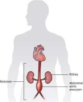
An Abdominal aortic aneurysm (AAA) represented in Figure 1.1, is the most common type of aneurysm. Abdominal aortic aneurysms are commonly located just below the renal arteries (infrarenal) but above the point in which the descending aorta bifurcates into the two common iliac arteries. It is not rare to have involvement of the common iliac arteries, but hypogastric and external iliac arteries are usually spared from aneurismatic degeneration.
3
The occurrence of AAA varies markedly by ethnicity. In the United Kingdom the rate of AAA in Caucasian men older than 65 years is about 4.7% while in Asian men it is 0.45% (Salem, et al., 2009). There are 9000 deaths yearly in the United States due to AAA rupture (Creager, et al., 1996). Other risk factors include hypertension and male sex. The frequency varies strongly between males and females. The peak incidence is among males around 70 years of age, the prevalence among males over 60 years total 2-6%. The frequency is much higher in smokers than in non-smokers (8:1), and the risk decreases slowly after smoking cessation (Wilmink, et al., 1999).
Rupture of the AAA occurs in 1-3% of men aged 65 or more, the mortality is 70-95% (Lindholt, et al., 2005).
1.2 Aneurysm treatment options
Historically, the treatment of arterial aneurysms has been limited to either surgical intervention, or watchful waiting in combination with control of blood pressure. In recent years, endovascular or minimally invasive techniques have been developed for many types of aneurysms.
The treatment options for asymptomatic AAA are conservative management, surveillance with a view to eventual repair, and immediate repair. There are currently two modes of repair available for an AAA: open aneurysm repair and EVAR. An intervention is often recommended if the aneurysm
Figure 1.1 - Abdominal aortic aneurysm. Reproduced from Kleinstreuer, et al., 2007.
4
grows more than 1 cm per year or it is bigger than 5.5 cm. Repair is also indicated for symptomatic aneurysms (Greenhalgh & Powell , 2008).
The following topics describe these two distinct ways to operate the treatment of an AAA.
1.2.1 Open surgical repair
Treatments of AAAs utilize implants that work to depressurize the aneurysm while creating a new blood pathway. Traditionally (1951 - current), the available treatment required for patients with high risk of rupture is open surgical repair (Schneider, 2008).
Specifically, an open surgery (Figure 1.2) involves a large incision and surgical exposure of the infra-renal aorta and iliac arteries, replacement of the diseased aorto-iliac segment with a synthetic prosthetic graft made of polyethylene terephthalate (Dacron or PET) or polytetrafluoroethylene (PTFE) in an “in-lay” fashion.
This graft then acts as a synthetic vascular replacement reinforcing the diseased arterial tissue. Standard open repair is well documented to show its effectiveness and durability in treating AAAs yet in some centers it has been shown to have rates of mortality of 5-10% and major complications (Schneider, 2008). Though open repair is the standard and still performed it may not be the best
Figure 1.2 - AAA open surgical repair procedure. Adapted from Schwarz, 2012.
5
choice of procedures depending on patient’s age, condition and or medical history. Along with mortality open repair have possible perioperative and post-operative complications including morbidities such as, myocardial infarction, respiratory complications, excessive bleeding and prolonged reduced blood flow for the lower extremities. The last two decades have brought about a new, less invasive alternative – endovascular aneurysm repair (EVAR).
1.2.2 Endovascular aneurysm repair
Endovascular aneurysm repair (EVAR) represented on Figure 1.3, is a minimally invasive technique to treat aneurysms. The first EVAR procedure was reported by Parodi et. al in 1990. A stent-graft (SG) or endograft is an endoprosthesis classified as a class III medical device both in Europe and in the United States of America. It can be defined as a tubular device composed of a flexible membrane, i.e., a graft, supported by a rigid structure. The skeleton, called the stent, acts as an arterial attachment mechanism and provides structural support to both the graft and the treated vascular segment. The graft forms a new conduit that protects the diseased artery from the pulsatile blood pressure.
In EVAR, a SG is crimped by concentric radial compression and placed into a flexible catheter. A small incision is made in a femoral artery where the catheter is inserted and guided up the artery until it reaches the abdominal aorta in order to shield the aneurysm from the blood pressure, eliminate blood circulation in the aneurysm sac, and ultimately prevent wall rupture.
To perform that, the stent graft is then positioned where the proximal and distal ends would contact regions of healthy tissue. It is then deployed into the lumen of the artery.
Figure 1.3: Endovascular aneurysm repair. Reproduced from Schwarz, 2012.
6
The biggest advantages of this minimally invasive procedure with respect to open surgery are: smaller incisions, less blood loss, decreased pain and quick recovery (Fu, et al., 2009).
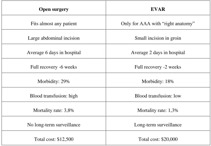
Table 1.1 provides a comparison between the traditional surgical intervention and EVAR. Clearly, EVAR is safer than open surgery; however, it is only suitable for patients who have the suitable AAA anatomy. Presently, only 60%-70% of AAAs can be repaired by EVAR (Schneider, 2008).
Table 1.1 - Comparison between open surgery and EVAR. Adapted from (Noll, et al., 2007 ).
Open surgery EVAR
Fits almost any patient Only for AAA with “right anatomy”
Large abdominal incision Small incision in groin
Average 6 days in hospital Average 2 days in hospital
Full recovery -6 weeks Full recovery -2 weeks
Morbidity: 29% Morbidity: 18%
Blood transfusion: high Blood transfusion: low
Mortality rate: 3,8% Mortality rate: 1,3%
No long-term surveillance Long-term surveillance
Total cost: $12,500 Total cost: $20,000
Interestingly, the cost is much higher than that for open surgery, mainly because of the need for long-term annual check-ups.
However, EVAR is a relatively new technology without long-term follow-up outcome. While it has shown outstanding success for patients with abdominal aortic aneurysms (AAAs), it can also cause many problems, such as seepage of blood into the cavity (endoleaks), SG migration, SG failure, and other complications.
The postplacement cost of EVAR increases the global cost by 44% (Noll, et al., 2007 ). The subgroups of patients with endoleaks and those requiring secondary procedures generate a
7
disproportionate share of postplacement costs. Efforts at minimizing cost should emphasize technical and device modifications aimed at reducing endoleaks and the need for secondary procedures.
1.3 Chimney graft technique
The proximal stent graft landing zone is considered to be the fundamental part of EVAR, as optimal fixation and sealing are essential for technical and clinical success of this procedure. The morphology of the proximal aneurysm neck is therefore important in determining whether the patients are considered suitable for the endovascular exclusion of an aneurysm. Approximately 20% to 30% of the patients are considered not eligible for EVAR owing to their anatomy (Greenberg, et al., 2003).
Fenestrated and branched endoprosthesis have been introduced, and newer techniques such as the chimney procedure have been described, all with the purpose of widening the therapeutic range of EVAR by expanding the proximal seal zone beyond the renal arteries. Fenestrated and branched stent graft were a modification in the technique of EVAR, which made branch preservation possible. Although good results have been obtained with these grafts, they have to be custom-made for each individual patient, which is a time-consuming and expensive procedure.
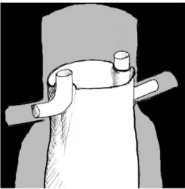
Chimney graft (CG), is an EVAR technique in which a stent is deployed parallel and outside of the aortic endograft to preserve flow to a vital aortic branch that was overstented to obtain an adequate seal (Figure 1.4).
Figure 1.4: Schematic drawing of the CG technique. Reproduced from Ohrlander, et al., 2008.
8
Greenberg et al. (2003) were the first to describe the use of renal stents in patients with a short proximal neck for the preservation of branch patency. With the introduction of the chimney procedure, a ready available alternative to a fenestrated stent graft, for the treatment of acute aneurysm in patients with challenging anatomy when there is no time to manufacture a fenestrated device. Table 1.2 presents a resume of the comparison between chimney graft technique and the use of fenestrated grafts.
Table 1.2 - Comparison between chimney graft and fenestrated graft
Since then, the technique has been describe by others, and is referred to as double-barrel or snorkel technique.
The technique has been used in the renal arteries, superior mesenteric artery (SMA), left subclavian artery (LSA), left common carotid artery (CCA), and innominate artery (Ohrlander, et al., 2008). So far, the number of patients treated with a CG is limited and follow-up is short; however, no late CG-related endoleaks have been noted on follow-up to date. Several studies, however, show a high rate of spontaneously resolved type I endoleaks, possibly due to the formation of clot or poor outflow (de Bruin, et al., 2013).
1.4 Post-op Problems associated with stented AAAs
A well-placed and anchored SG forms a new blood vessel, i.e., segments of the aorta plus iliacs, and hence completely protects the weakened aneurysm wall from the pulsatile blood pressure. However,Chimney grafts Fenestrated grafts
“Off the shelf” More anatomic branch revascularization
Suitable for urgent AAA cases Needs more planning
Cheaper and possibly easier Custom made
9
various postoperative complications may occur, for example the device migration, but endoleaks are the most frequent and severe.
1.4.1 Endoleaks
Endoleaks are the persistence of small blood flow occurring between the stent-graft and the AAA wall, pose the most frequent problem after endovascular therapy of aortic aneurysms. As a result, endoleaks may cause elevated intrasac pressure and high stresses in the AAA wall. Serious endoleaks can result in SG failure or AAA rupture and hence the need for a second procedure. Presently, four endoleak types are defined in the literature (Figure 1.5): leakage at the anchor sites (Type I, if proximal Ia, if distal Ib), leakage via collateral arteries (Type II), defective SG (Type III) and leakage owing to porosity of the graft material (Type IV) (Kleinstreuer, et al., 2007).
Figure 1.5 - Four types of endoleaks: I – Anchor sites, II – Via collateral arteries, III – Defective SG and IV – Porosity of the SG. Reproduced
10
Chapter 2
Methods
In order to study the endoleaks type Ia formed in CG configurations, i.e. the leakage areas formed at the proximal anchor sites, and examine how the deformation occur in the endografts, we choose an approach in Finite Elements.
The Finite Element Method (FEM) is a numerical technique to obtain an approximate solution to a class of problems governed by partial differential equations known as boundary value problems as they consist of a partial differential equation and the boundary conditions. This method converts the partial differential equation into a set of algebraic equations which are easy to solve. Without doubt FEM has emerged as one of the most powerful numerical method so far devised and is accepted as the standard analysis method due to its generality and suitability for computer implementation. This method divides the model into many small pieces of simple shapes called elements effectively replacing a complex problem by many simple problems that need to be solved simultaneously. Elements share common points called nodes and the process of dividing the model into small pieces is called meshing.
The response at any point in an element is interpolated from the response at the element nodes. Each node is fully described by a number of parameters depending on the analysis type and the element used. For example, in a structural analysis, the response of a node is described, in general, by three translations and three rotations. These are called degrees of freedom (DOFs). Analysis using FEM is called Finite Element Analysis (FEA).
Advantages of the finite element method over other numerical methods are follows:
The FEM can be used for any irregular shaped domain and all types of boundary conditions;
11
Accuracy of the solution can be improved either by proper refinement of the mesh or by choosing approximation of higher degree polynomials;
The algebraic equations can be easily generated and solved on a computer;
A general purpose code can be developed for the analysis of a large class of problems. The FEM has become very important to solve engineering problems, allowing solving cases that until recent time were virtually impossible by traditional mathematical methods. The FEM provides a mathematical model for calculating the real system, easier and cheaper to change than a prototype. However, it remains as an approximate calculating method due to the basic assumptions of the method. Therefore, prototypes are still necessary, but in lower quantity, since the first one can be well approximated to the optimum design.
The software SolidWorks (Dassault Systèmes SolidWorks Corp., Concord, MA, USA) is solid modeling CAD (computer-aided design) software which utilizes a parametric feature-based approach to create models and assemblies. It has also a tool – SolidWorks Simulation Premium which is a FEA design validation tool that shows engineers how their design will behave as physical objects.
This software formulates the equations governing the behavior of each element taking into consideration its connectivity to other elements. These equations relate the response to known material properties, restraints, and loads. Next, the program organizes the equations into a large set of simultaneous algebraic equations and solves for the unknowns.
SolidWorks was the software used not only for the design of the parts (SG’s and Aorta) but also to simulate the displacements of the parallel SG’s inside aorta and the calculation of the gutter areas. Considering that a simulation study is defined by the following factors:
Model dimensions
Study type and related options to define analysis intent
Material properties
Loads and boundary conditions
The Second Chapter describes all these factors. The first part contemplates the design of SG’s and Aorta (construction of the geometric models) and the second the one is the assembly of these two in one of the possible Chimney configurations - simulation study.
12
2.1 SG models design
Through the information of the Department of Endovascular Surgery of Santa Marta Hospital, we considered the most used SG in EVAR (main bodies and “parallel” stents) which are presented in Table 2.1 and Table 2.2 respectively.
Table 2.1 - Stent grafts used in EVAR (Main bodies). Adapted from (Bryan Mawr Communications, 2012).
Company SG name Graft material Stent material Diameters (mm)
W.L. Gore Excluder ePTFE Nitinol 28, 31
Cook Medical Zenith Woven Polyester
Stainless steel 28, 32
Medtronic Endurant II Woven Polyester
Cobalt Chromium
28, 32
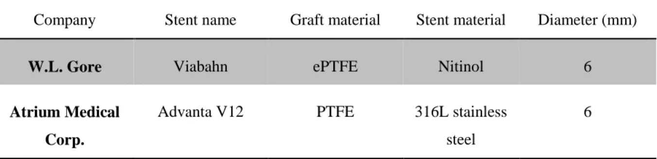
Table 2.2 – Parallel stents used in Chimney Graft Technique. Adapted from (Bryan Mawr Communications, 2012).
Company Stent name Graft material Stent material Diameter (mm)
W.L. Gore Viabahn ePTFE Nitinol 6
Atrium Medical Corp.
Advanta V12 PTFE 316L stainless steel
6
The initial approach was to establish research agreements with W.L. Gore, Cook Medical, Medtronic and Atrium Medical Corp. in order to design geometric models with the exact dimensions of these stents and use the correct material properties. However, due to the intellectual property these confidential information could not be sent.
13
However, since all of these stents hava a similar “sinusoidal” shape (Figure 2.6), the problem was simplified and it was designed only two stent grafts with a similar metallic shape of the commercial models in two different inner diameters: 6 and 28 mm.
These two stents were designed with SolidWorks software and are represented on Figures 2.7 and 2.8.
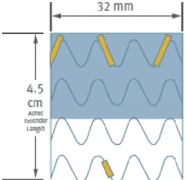
Figure 2.6 - Excluder SG "sinusoidal" metallic stent shape
14
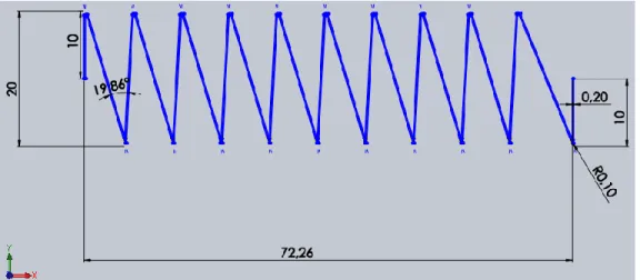
The dimensions used in the construction of these two models are illustrated on Figure 2.9 and 2.10 (respectively 28 and 6 stent). The thickness of the both stents is 0,2 mm and they have 20 mm of height.
Figure 2.8 - Isometric view of 6 mm Stent
15
The graft is a tissue usually made of expanded polytetrafluoroethylene (Gore-Tex or ePTFE), PTFE or PET (Dacron) and acts as the sealing agent in order to keep the aneurysm depressurized. Is typically either sutured or adhered to the inside of the stent depending on the device.
To design this tissue, both stents were concentric assembled with a hollow cylinder with 0,1 mm of thickness resulting in a covered stent. The final appearance of the SG’s is exemplified on Figure 2.11. for the 6 mm SG.
Figure 2.10 - Dimensions in millimeters of 6 mm Stent
16
2.2 Abdominal Aorta segment Design
The abdominal aorta is the largest artery in the abdominal cavity. As part of the aorta, it is a direct continuation of the descending aorta.
The average diameter of the aorta is 20-25 mm. The wall of the artery is composed by three different layers: intima, media, and adventitia which have different mechanical properties and thicknesses - 0.2 mm, 1.2 mm, and 0.6 mm, respectively (Vasava, et al., 2012).
According with this information and considering a straight small segment in abdominal aorta, it was designed a hollow cylinder with 60 mm of length and 2 mm of wall thickness which represents a simple geometric model of abdominal aorta. The final result is presented on Figure 2.12.
Note that, the inner diameter of aorta segment, was calculated in order to fit in each CG configuration.
2.3 Assembly in a Chimney Graft configuration
After the design of the SG’s and the segment of Abdominal Aorta, the following step was the assembly of these parts in a Chimney Graft configuration.
A CG configuration is composed by a main body SG and the “parallel” or “parallels” stents which will vascularize the adjacent arteries.
Figure 2.12 - Dimetric view of the designed segment of abdominal aorta
17
According with the Figure 2.13 which shows the closest arteries of abdominal aorta, it is possible to identify various adjacent arteries such as: iliac, renal and inferior mesenteric. Taking into account medical experience information we defined a number maximum of 4 stents to introduce as secondary bodies to our study.
Besides that, with the intention of trying something groundbreaking we chose to test also the use of two main bodies in parallel. These options resulted in a total of 15 different CG configurations which are represented on Tables 2.3 and 2.4, according with the number of main bodies used (one or two respectively).
18
Table 2.3 - CG configurations with one main body (Black circle – main body; Red circles - parallel stents)
Number of side branches Scheme of configurations
1
2
3
4
Table 2.4 - CG configurations with two main bodies (Black circles – main bodies; Red circles parallel stents)
Number of side branches Scheme of configurations
1
2
19
The disposition of the side branches was chosen with the help of Dr. Frederico Gonçalves, by his experience in endovascular procedures. However, some of them are just random hypotheses which appeared to be reasonable and raise the specter of this study. They are numbered 1-15.
All of these configurations were concentric involved by the abdominal aorta segment constructed. For all the configurations of Table 2.3, the inner diameter of the artery is 35.2 mm, for configurations 12, 13 and 15 is 57.2 mm and for the configuration 14 is 70.4 mm.
These three parts, aorta and the two SG’s, have the front face coincident and the SG’s are tangential assembled between them and with the artery. As an example, looking for the first configuration on Table 2.3, composed by one main body and one side stent, the final stage of the geometric model is presented on Figure 2.14.
Figure 2.14 - Final geometric model of Configuration 1 - Segment of Abdominal aorta (red) concentric and tangential assembled with a
20
2.4 Finite Element Analysis
A simulation study is complete performing the following steps:
Create a study defining its analysis type and options
Define material properties
Specify restraints and loads
Define component contact and contact sets
Mesh the model to divide the model into many small pieces called elements
Run the study
View results
2.4.1 Type of study
There are many types of studies offered by SolidWorks software: Static, Frequency, Buckling, Thermal, Design, Nonlinear, Linear Dynamic, Drop Test, Fatigue, Pressure Vessel Design and 2D Simplification.
The Linearity assumption says that the relationship between loads and induced responses is linear. This assumption can only be made if:
All materials in the model comply with Hooke’s law, i.e. the stress is directly proportional to strain;
The induced displacements are small enough to ignore the change in stiffness caused by loading;
Boundary conditions do not vary during the application of loads.
However, once the material properties of abdominal aorta are nonlinear, this study has large displacements and since it is a contact problem because the boundary conditions change when loading contact occurs, the type of study chosen was Nonlinear Static.
Nonlinear Static analysis is based that stress and strain does not follow Hooke’s Law (i.e. nonlinear relationship between stress-strain due to material plasticity), deformations are covered by large deflection theory (i.e. large geometric difference between initial and deformed shape) and all loads
21
are applied slowly and gradually until they reach their full magnitudes. After reaching their full magnitudes, loads remain constant (time-invariant).
2.4.2 Material Models
A material model describes the stress-strain relation for a material. Available material models depend on the type of the active study. For nonlinar studies, SolidWorks mainly consider 5 distinct types of models: Linear elastic, NonLinear elastic, Plasticity, Hyperelasticity and Nitinol material. To characterize well a material is necessary perform mechanical tests in order to evaluate its properties, such as radial stiffness, flexural rigidity, and shear rigidity. Once our stent is just a fictional prototype and we did not have a real model to evaluate these mechanical properties and since there is a straight relationship between the mechanical properties of the stent and the design variables (width, thickness, angles…), the properties defined are related with the materials used in commercial models.
According to the commerical SG’s models presented on topic 2.1. (Excluder and Viabahn (W.L. Gore, Inc.), Advanta V12 (Atrium Medical Corp.), Zenith (Cook Medical) and Endurant II (Medtronic)), we found that 316L Stainless Steel, Cobalt-Chromium alloys and Nitinol are some widely-accepted materials used in stent fabrication by manufacturers. Nitinol, is a nearly equiatomic alloy of nickel and titanium. Unlike traditional engineering materials like stainless steel exhibits the unusual properties of shape memory and superelasticity. These properties are manifestations of a phase change that occurs in the material as it transitions between a higher temperature (austenite phase) and a lower temperature (martensite phase).
At present there are 2 basic types of stents as regards the method of implanting and the material used:
Stents implanted by the use of the balloon - The use of the ballon makes the advantage of the plastic properties of steel and enables precise installation of a stent. Once expanded above the plastic properties of the steel does not change its shape.
Self expanding stents – Nitinol self expanded, can take different shapes depending on local deployment and temperature (expanding under the influence of heat).
22
Once the stents implanted with the use of a balloon have been situated in the centre of our interests, we opted to choose 316L Stainless Steel in detriment of Nitinol for the metallic stent, in order to exclude the variable temperature of our analysis.
For the fabric, taking into account the most used materials in commercial SG’s we opted to use the PTFE instead of ePTFE due to the lack of information about the exact mechanical properties. The material models of 316L stainless steel and PTFE were assumed to be isotropic and linear elastic and their mechanical properties are presented on Table 2.5.
Table 2.5 - Mechanical properties of SG's components
Material Elastic Modulus (MPa) Poisson’s Ratio Shear Modulus (MPa) Mass Density (kg/𝐦𝟑) Tensile Strength (MPa) Yield Strength (MPa) References Stainless Steel 316L 200000 0.265 82000 8027 485 170 (Davis, 1998)
PTFE 552 0.46 15.1 2200 34.5 21.7 (Suzuki, et al., 2001)
The material of the artery wall was modelled using a 5-parameter third-order Mooney-Rivlin hyperelastic constitutive equation which is suitable for incompressible isotropic material.
In continuum mechanics, a Mooney-Rivlin solid is a hyperelastic material model, i.e. a type of constitutive model for ideally elastic material for which the stress-strain relationship derives from a strain energy density function W which is a linear combination of two invariants (𝐼1 and 𝐼2) of the
left Cauchy-Green deformation tensor. The strain-energy density for this material is given in Equation (1) (Mooney, 1940) :
23
By using the uniaxial and equibiaxial experimental data, Predengarst et. al (Prendergast, et al., 2005), introduced the hyperelastic constants in Equation (1) for the arterial wall, as given is Table 2.6.
Table 2.6 - Hyperelastic constants to describe the arterial tissue
Constant Artery wall tissue (kPa)
𝒂𝟏𝟎 18.9
𝒂𝟎𝟏 2.75
𝒂𝟐𝟎 85.72
𝒂𝟏𝟏 590.43
𝒂𝟑𝟎 0
The Young moduli for the arterial wall was assumed to be 6.562 MPa and also a incompressible Poisson ratio of 0.45 was chosen. The Young moduli value was an estimated proportional average through Gao et al. experiment, which presents areas and the different values of the Young’s modulus for the three different layers of the artery wall: intima, media, and adventitia respectively 2.98 MPa, 8.95 MPa, and 2.98 MPa (Figure 2.15).
Figure 2.15 - Aorta three layered model: Young Modulus of layers. Reproduced from Gao et al., 2006.
24
2.4.3 Loads, Contacts and Restraints
Oversizing (OS) is common practice and is perceived to benefit a graft in conforming to tortuous vasculature and reducing the occurrence of migration by increasing the attachment strength thus that is called the pullout force. Clinically, OS is calculated from the outer diameter of the SG and outer diameter of the abdominal aorta using the following equation:
𝑂𝑣𝑒𝑟𝑠𝑖𝑧𝑖𝑛𝑔 = 𝐷𝑆𝐺 𝐷𝐴𝑜𝑟𝑡𝑎
− 1 (2)
In a chimney graft technique, a link between oversizing and folding in stent grafts is to be expected. For an oversized stent graft to fit inside an aorta, it needs to expand the aorta or compress itself, or both. Thus, the precise relationship between oversizing and folding is likely nonlinear.
To simulate oversize, we had 2 options:
Overdesign the artery in order to assembly the SG’s inside with the stipulated dimensions (6 mm of diameter for the CG’s and 28 mm of diameter for the main bodies) in one of the configurations and then apply external compressive pressure in order to reduce aorta to 25 mm of diameter;
Design the artery with the regular dimensions (25 mm of diameter), assembly all the SG’s with 6 mm of diameter, including the main body(ies), and then apply to the main bodies an internal expanding pressure till they reach 28 mm of diameter.
We opted for the first one despite the second which actually portraits what happens in reality. Mostly because of the computational/solver numerical difficulties (high computational cost) and in order to compare results of the experimental study of de Bruin, et al. which studied with a physical model our CG configuration number one using different commercial SG’s.
The compressive pressure was performed using an advanced fixture for cylindricall faces which was applied at the interior cylindricall face of aorta in order to reduce it to the diameter of 25 mm. The arterial pressure is not taken into consideration in the simulation since the loads deriving from the contact interaction of the at least three bodies are much higher.
In order to avoid rigid-body motions and to construct a good-conditioned system of equations, appropriate boundary conditions were applied.
25
Since in this study only interests the displacements at the top section in order to calculate the gutter areas, the boundary conditions chosen were the following: (i) the end faces of all parts were bounded in all three directions; (ii) the y- and z- displacements of a node of the stents located on its middle plane was fixed, allowing the radial expansion/compression of the stent but not its rigid motion.
The contact between the external cylindrical faces of the SG’s and internal wall of aorta was set as No Penetration. The fabric and the stents have a bonded component contact.
2.4.4 Mesh
The automatic mesher in the software generates a mesh based on a global element size, tolerance, and local mesh specifications. The software estimates a global element size for the model taking into consideration its volume, surface area, and other geometric details.
The geometry of the grafts were meshed automatically using 2D triangular shell elements which are naturally suitable for modelling thin parts. The stents and aorta were meshed as solid parts.
After the meshing, for the first configuration were obtained:
36,463 degrees of freedom
15,869 nodes
59,062 elements
In Figure 2.16 is represented configuration 1 before processing the study.
26
In Figure 2.16 it is possible to observe the aorta and the SG’s meshed with triangular elements, the green arrows which represents the constraints and the red arrows which are the compression forces applied by the artery in the endografts.
Before running the study, the large displacement option was activated once the small displacements options assumes that the contact areas do not change direction during loading and this approach may lead to inaccurate results or convergence difficulties. The type of solver chosen was Sparse.
2.4.5 Calculation of gutter size
After running the study, the expected result is shown in Figure 2.17. The Figure shows different cross-sectional areas in configuration 1 (one main body and one stent in parallel or CG). The area D indicated represents the gutter area.
The method to determine gutter areas consists in sketch in the front plane the countor of the area, extrude it and then use the measure tool of the SolidWorks to obtain the precise area in 𝑐𝑚2.
The endografts compression was calculated by subtracting the area of the endografts from the aortic area. In addition, the compression was calculated relative to the aortic area.
Figure 2.17 - Different cross-sectional areas in configuration 1. A: outer perimeter of the main graft, B: inner diameter of the aorta, C:
outer perimeter of the chimney graft, and D: gutter. Reproduced from de Bruin, et al., 2013.
27
Chapter 3
Results and discussion
Absolute and relative values for gutter size and compression are enumerated in the Table 3.6 for configurations with one main body.
Table 3.6 – The 11 Different Chimney Graft configurations (one main body)
Configuration Number of CG’s
Gutter Area (𝐜𝐦𝟐)
Aorta Final Area (𝐜𝐦𝟐) Main Graft Compression % 1 1 0.441 5.88 14.6 2 2 0.563 8.41 41.9 3 2 0.466 8.19 43.2 4 2 0.518 8.32 44.5 5 3 0.679 12.91 69.7 6 3 0.583 8.60 50.5 7 3 0.682 13.28 67.2 8 3 0.646 9.93 59.7 9 4 0.755 15.21 75.6 10 4 0.713 14.34 76.1 11 4 0.984 16.63 77.0
The average gutter area for these CG configurations was 0.639 cm2 and the average aorta final area 11.06 cm2.
No significant differences in gutter size were observed between configurations with the same number of CG’s.
28
Relatively to relations between these variables, in Figure 3.18 is represented the variation of main graft compression and gutter area in each configuration and it seems difficult to take a conclusive relation.
Figure 3.18 - Relation between: Gutter Area, and Main Graft compression
However, relatively to the influence of the gutter area in the aorta final area, there is a direct proportional relation between these two variables which is shown in Figure 3.19.
Figure 3.19 - Relation between Gutter Area and Aorta Final Area
1 2 3 4 5 6 7 8 9 1 0 1 1
R E L A T I O N B E T W E E N G U T T E R A R E A A N D A N D M A I N G R A F T C O M P R E S S I O N
Main Graft Compression Gutter Area
1 2 3 4 5 6 7 8 9 1 0 1 1
R E L A T I O N B E T W E E N G U T T E R A R E A A N D A O R T A F I N A L A R E A
29
Clear is the fact that the number of CG’s increases the gutter area, as well as the aorta final area and the main graft compression. The average values for configurations with the same number of CG’s are presented on Table 3.7.
Table 3.7 - Average values for configurations with the same number of CG’s
Number of CG’s Gutter Area (𝐜𝐦𝟐)
Aorta Final Area (𝐜𝐦𝟐) Main Graft Compression % 1 0.441 5.88 14.6 2 0.516 8.31 43.2 3 0.648 11.18 61.8 4 0.817 15.39 76.2
All the configurations with more than 2 CG’s have main graft compression above 50%.
Note that there is a default pattern between the relative dispositions of the CG’s. The more closely CG’s configurations, have smaller gutter areas compared with configurations with the same number of parallel stents but diametrically opposed. The configurations with closely CG’s are: 3, 6 and 10, which had the lowest values of gutter area for each category (according to the number of parallel stents used).
Unfortunately, the results for CG with two main bodies were not obtained due to solver numerical difficulties.
The results show that compression is not concentrically symmetric but rather elliptical in nature. This is important when considering the effects of pressure due to oversizing on possible device failures such as folding and migration. This also could influence optimal stent design, barb location, and have an effect on endothelial tissue health where too much pressure could induce possible poor intimal layer ingrowth or localized necrosis.
One of the questions that arise with the fact that all the grafts collapse elliptically is why. We can speculate to this end that most likely it is a function of the contact interactions of the sleeve with the SG. Yet as we have learned the graft plays a critical role in the function of the stent graft device outside if being just a conduit for blood flow in order to depressurize the aneurysm. The graft material acts as the in-plane axial and circumferential support for the stent.
30
With this FEM approach of the CG technique, we found that the chimney grafts are well conformed in configurations with less than three parallel stents (main graft compression inferior to 50%). And the configurations with less number of CG’s, have small gutter areas, i.e. there is a limit size that a CG can be and still provide a seal and the risk of endoleaks increase with the number of CGs implanted.
However, the influence of the gutter areas and the main graft compression is not linear. Linearity is present between the number of CG’s used and the main graft compression, because the aorta lumen has always tend to have the same area regardless the number of the parallel stents used.
Already, the relation between the gutter area and the aorta final area is dependent. Since if the stent-grafts occupy well the “empty spaces”, which means lower gutter areas, this will contribute to reduce the final diameter of the artery.
Another important topic concerns to fact that the CG configuration with the lowest gutter area is the simple one (i.e. one main graft and one parallel stent). However, the difference between the other CG configurations are not so large but represent values for main graft compression far above to 50% hindering the use of these configurations.
The small differences in the different configurations could be a real point but is susceptible to represent a reading error due to the way used to measure the areas or eventually due to a formulation problem since crushing simulations are too difficult because of contact points, non-linear geometry, large deformation, sample buckling, stent bending and stress-strain non-non-linearity. On the other hand, the self-contact phenomenon is assumed only during contact between the edges of the stent in the crushing test.
Nevertheless, such as de Bruin et al. prove in his experimental study, which only testing a single CG configuration (one main body and one parallel stent), but with many combinations of commercial endograft models and different seal zones and diameters can represent very divergent results. Which notwithstanding that our study represents a good first approach, proves that is fundamental to be rigorous in the design of the models, have large samples, test different designs, materials and conformations in order to take assertive conclusions. This suggestions are presented in Chapter 6 – Future Perspectives.
Other point and in my opinion is the most interesting result of this analysis, is the fact that the configurations in which the disposition of the CG’s are closer, have small gutter areas. This observation, liable to be confirmed and studied in a deeper future research work, could be an interesting suggestion to change the way of dispose the parallel stents around the main graft.
This work is certainly not without its limitations. The inherent limitations concern to the fact of being a FEA. Despite being a good approach of the behavior between the artery and the sandwiched
31
SG’s there are some assumptions and simplifications made which limits the reality of the problem. Key issues in a reliable and valid simulation include the acquisition of valid source information about the behaviors and the use of simplifying approximations.
Assumptions and Simplifications made:
The way to simulate the oversize was not by expanding the stents, but compressing the aorta
The SG models do not have the same dimensions, geometry and mechanical properties of the commercial models
The model does not account for friction
Moreover, once we are measuring very small areas in which the smallest variation reproduce meaningful different final results we must take into account that the simplifications or values assumed namely about the geometric and mechanical parameters previously presented, including: length, thickness, width, shape of the stent struts; geometric distribution of the stent struts; the Young modulus and Poisson ratio are not the same of the commercial models and consequently not allow us to take very accurate results.
EVAR is still an evolving area of research and computer simulation of endovascular is an up-to-date research topic in computational biomechanics. These tools such as the finite element method have the potential to provide engineers and clinicians with patient-specific analysis to optimize medical devices such as stents, or to change the way to perform a certain endovascular procedure as CG technique in order to improve the clinical outcome.
Today, computer simulation of stent procedures is still a demanding task due to the complex material behavior of the involved components, and more importantly, due to the 3D contact interaction between the arterial wall and the endografts. Only a very complex computational model accounting for the interaction with the stent and the balloon would reproduce correctly the free expansion of the stent. Moreover, such developments should help improve SG design.
Further, computational studies involving fluid-structure interaction analysis and material-fatigue analysis need to be performed to clarify the mechanical behavior of stents in reference to radial stiffness, bending resistance, number and formation of hinge points, stent conformation to arterial morphology, biologic changes of a bending segment in terms of restenosis, and material fatigue that may result in stent fracture.
32
Chapter 4
Conclusion
The treatment of AAAs represents one of the greatest challenges in endovascular procedures. So far there are three options:
I. Open aortic reconstruction;
II. Endovascular repair with fenestrated endografts; III. Endovascular repair with chimney grafts.
Endovascular aneurysm repair has become a popular treatment for abdominal aortic aneurysms because of the decreased morbidity and early mortality associated with this method compared with open repair. However, both short- and long-term success with this technique requires the achievement of secure seal at the proximal and distal attachment sites. Therefore, patients with aneurysms involving or in close proximity to important branch vessels have traditionally been excluded from EVAR.
Parallel endografting or chimney technique is one method proposed to extend the applicability of endovascular repair to these patients by taking advantage of seal zones that cross these branch vessels. The method is appealing because it uses off-the-shelf devices for immediate availability. Further, the modular nature of the technique enables potential applicability to almost any anatomy. The chimney graft may be a valid alternative to a fenestrated stent-graft in the emergency setting, when a diseased segment is unsuitable due to vessel tortuosity, or there is no time to manufacture a fenestrated device.
Early experience with the chimney technique has shown promising results. Unfortunately, as already described, the main question against the efficacy of the chimney graft technique lies in the development of type I endoleak, mainly due to the inadequate proximal sealing of the repair.And
33
there is controversy regarding the optimal configurations of stent grafts. Success with this technique, therefore, will likely depend on strategies that overcome this flaw.
Due to the relevance of study the development of type I endoleak in CG technique, and the lack of research published about “optimal CG configuration in which gutters are smallest”, this work is a good start to future projects, since this master project provided an insight view of the AAA treatments and a valid and useful finite element method to analyze simple parallel endograft stenting configurations.
In this FEA of an abdominal aortic aneurysm segment model with various CG’s configurations, balloon expanded endografts conformed well for 1 and 2 parallel stents without compromise the main graft (compressions less than 50%). However, using more than two parallel stents, there is a conceptual problem once the 50% compression of the main graft render the configuration unusable. Furthermore, configurations with more parallel stents showed large gutters and an increase in the main graft compression which do not support the use of these combinations in the chimney technique.
The most important result in this work is the influence of the disposition of the CG’s. The results obtained show that configurations with closer parallel stents have lower gutter areas which could be a revolutionary hint for future endovascular surgeons.
Unfortunately the sample is too small to take solid conclusions, but represents a good first approach for future work, since with this work it was established a method to deeply analyze stents expansion and deformation in contact.
Due to computational or formulation problems, any conclusion was made about the use of two main grafts in CG technique.
The presented results provide evidence of the ability and effectiveness of the computational tools to treat challenging 3D contact problems such as the 3D simulation of CG technique or a balloon angioplasty with stenting. However, there are challenging future works in order to improve and take more conclusions. More data is required before this promising technique can be widely advocated. In summary, the use of the chimney technique expands the applicability of EVAR for the management of complex AAAs. However, the efficacy and safety of this endovascular technique needs to be investigated in further long-term studies.
34
Chapter 5
Future Perspectives/Recommendations
Future development should be addressed in order to overlap the limitations presented and concern to the following aspects:
Use different commercial models because there are main grafts with more radial force than others and they could have different effects on the geometry of the CG configurations and therefore gutter size
Design commercial models with the exact geometry, through imaging techniques imported to CAD programs or obtaining a confidentiality agreement with several companies in order to get the exact geometry
Make mechanical tests in order to obtain accurate material properties of the different SG’s
Test different materials and model types in order to observe their influence
Test Nitinol stents, which have particular interesting characteristics as shape memory and super elasticity. And compare the results between a self-expanded stent and a stent expanded by balloon
Model the oversize differently from the way it was done, to prove the versatility of this setup
Test different diameter sizes and the maximum combination of all variables (diameters, models, materials…) in order to have a large sample and take more trusting conclusions
Try to understand the influence of the materials and the design - testing different shapes and dimensions of the structure of stent wires and ranging values of: Young Modulus, Poisson’s Ratio, Tensile Strength, Yield Strength, Tangent Modulus, Mass Density and Compressive Strength
Improve the method of restraints and contacts in order to reduce the computational progress to allow to complete the study for CG technique with 2 main bodies. It is also important to
35
refer that the forces are carried by the stent wire, which mainly controls how the deformation of the endografts happens. This means that future works, can be possible simplified using only the metallic wire neglecting the graft fabric, which represents less elements to design and significant less computational time
Furthermore, future work can go deep and it is obvious that more experiments and simulation results related to blood pressure, friction and residual stresses are needed to reach a comprehensive conclusion. Lack the simulation with proper software of computational fluid dynamics (CFD) to take into account the characteristics of aorta behavior, i.e. the mechanical interaction between the various stents and the vessel wall and blood flow dynamics.
Experimental investigations should be done to assess the optimal properties of the aortic stent-graft and CG’s needed for proximal seal and side branch patency. Therefore, prototypes and in vivo tests are still necessary to prove the best practice in CG technique.
Another aspect concerns to the software used. SolidWorks is an excellent CAD program, however all the studies published in the scientific community used other software’s to work in FEM as ABAQUS or ANSYS, once mesh density and element type can be controlled by the user in order to improve accuracy of results. ABAQUS software is also a good option since it proved to be very useful in solving sophisticated numerical issues such as contact, buckling, and superelastic materials.
For that reason, but not referred in previous topics, this work was first planned in order to use ANSYS 14.0 (ANSYS Inc. Canonsburg, PA) for FEA modeling and simulation.
Unfortunately this initial project was not possible to conclude because the lack of a valid license and the impossibility to perform mechanical tests. However, the code written is in appendix 1, and could be availed in the future. In Figure 6.20 is presented an image of the first configuration represented by 3 cylinders (Aorta and the inside endografts).
36
This approach would be groundbreaking once we possibly could ignore the stent geometry and simplify the endografts in hollow cylinders. These cylinders would have a fictional material properties and thickness, extracted by the following mechanical tests:
Pure compression stiffness of the material (tri-axial test)
Compression tensile (uni-axial test)
Flexural compression (uni-axial test)
Being possible, this could significantly simplify the problem and reduce the computational problems.