F
ACULDADE DEE
NGENHARIA DAU
NIVERSIDADE DOP
ORTOAdvanced 3D Computer Vision
Approach to Clinical Motion
Quantification for Neurological Diseases
Diogo Peixoto Pereira
Mestrado Integrado em Engenharia Informática e Computação Supervisor: PhD João Paulo Trigueiros da Silva Cunha
c
Advanced 3D Computer Vision Approach to Clinical
Motion Quantification for Neurological Diseases
Diogo Peixoto Pereira
Mestrado Integrado em Engenharia Informática e Computação
Abstract
The humans motor capabilities can be seriously compromised by neurological diseases like Parkin-son and Epilepsy, which in turn worsen their quality of life. Human motion analysis can help to study and diagnose these diseases by providing information related to the gait and other physi-cal motions of the patients. There are already systems being used in the fields of Parkinson and Epilepsy that study and provide very useful information about the neurological impairments of the patients using the Kinect V2 from Microsoft (RGB-D camera). These systems use one application to acquire the information from the camera (Kit - KinecTracker) and two other applications that analyse the data acquired, KiMA (Kinect Motion Analyzer) and KiSA (Kinect Seizure Analyzer). Until now, the cameras used on the KiT application has been the Kinect V2 and previously the Kinect V1.
In this thesis, a new system divided into two applications that use the new Azure Kinect from Microsoft is presented. This system has similar functions to the KiT but his adapted to the new functionalities of the Azure Kinect. The first application enables the acquisition and visualization of the images captured by the Kinect, namely the color, depth and infrared (IR) images. The second application segments the information gathered by the first application. The result is a portable system that can be used within the clinical context to gather the motion information of the patients with neurological diseases.
Keywords: Azure Kinect. RGB-D camera. computer vision. movement-related neurological diseases.
Resumo
As capacidades motoras humanas podem ser seriamente comprometidas por doenças neurológicas como Parkinson e Epilepsia, que por sua vez pioram a qualidade de vida do ser humano. A análise do movimento humano pode ajudar a estudar e diagnosticar essas doenças, fornecendo informações relacionadas à marcha e outros movimentos físicos dos pacientes. Já existem sistemas a serem usados nos campos de Parkinson e Epilepsia que estudam e fornecem informações muito úteis sobre as deficiências neurológicas dos pacientes, utilisando as capacidades do Kinect V2 da Microsoft (câmara RGB-D). Esses sistemas usam uma aplicação para obter as informações da câmera (Kit - KinecTracker) e outras duas aplicações que analisam os dados adquiridos, o KiMA (Kinect Motion Analyzer) e o KiSA (Kinect Seizure Analyzer). Até agora, as câmeras usadas na aplicação KiT foram o Kinect V2 e anteriormente o Kinect V1.
Nesta tese, é apresentado um novo sistema dividido em duas aplicações que usam o novo Azure Kinect da Microsoft. Este sistema tem funções semelhantes ao KiT, mas foi adaptado às novas funcionalidades do Azure Kinect. A primeira aplicação permite a aquisição e visualização das imagens capturadas pelo Kinect, nomeadamente, as imagens de cor, profundidade e infraver-melho (IR). A segunda aplicação segmenta as informações adquiridas pela primeira aplicação. O resultado final é um sistema portátil que pode ser usado no contexto clínico para reunir as infor-mações de movimento dos pacientes com doenças neurológicas.
Keywords: Azure Kinect. RGB-D camera. computer vision. movement-related neurological diseases.
Acknowledgements
I would like to express my sincere gratitude to my supervisor PhD João Paulo Cunha for rewarding my good efforts and for being tough on me when I needed to work harder. To the BRAIN members for being so welcoming and being always ready to help. A special thanks to the Machine Learning Researcher Tamas Karacsony for all the technical support during the development of the product. A special thanks to my family for all the support. To my sister that worked next to me during the quarantine times. And to my parents for being always their, specially in the last couple of weeks before the deadline for this thesis.
I would also like to thank my friends Pedro Silva, António Almeida, Gonçalo Moreno, Ana Eulálio, Ana Gomes, Josefa Fonseca and Roberto Moreira that helped me keep my sanity during these complicated times. And also a special thanks to my friend Catarina Ribeiro for all the talks and laughs that we had.
Diogo Peixoto Pereira
“ Those who dream by day are cognizant of many things which escape those who dream only by night”
Edgar Allan Poe
Contents
1 Introduction 1 1.1 Context . . . 1 1.2 Motivation . . . 2 1.3 Objectives . . . 2 1.4 Thesis Outline . . . 32 State of the art 5 2.1 Diagnosis of Epileptic seizures and Parkinson’s disease . . . 5
2.1.1 Epileptic seizures . . . 5
2.1.2 Parkinson’s disease . . . 7
2.2 Motion capture technologies . . . 7
2.2.1 Motion capture algorithm . . . 8
2.2.2 Background of motion capture systems . . . 9
2.2.3 Motion capture systems in clinical environments . . . 12
2.3 Kinect evolution . . . 13
2.3.1 Kinect from XBOX 360 . . . 13
2.3.2 Kinect V2 . . . 14
2.3.3 Azure Kinect . . . 16
3 Azure Kinect and KiT 19 3.1 Azure Kinect . . . 19
3.1.1 Overview . . . 19
3.1.2 Azure Kinect SDK . . . 21
3.2 The KiT decision . . . 22
3.2.1 The KiT and the hospital environment . . . 22
3.2.2 Azure Kinect Mode Preliminary Tests . . . 24
3.2.3 The KiT problems and the decision . . . 26
4 Azure KiT development 29 4.1 Development tools . . . 29
4.2 Azure Kit part 1 . . . 30
4.2.1 Requirements and Mockups . . . 30
4.2.2 Development Process . . . 32
4.3 Azure Kit part 2 . . . 35
4.3.1 Requirements and Mockups . . . 35
4.3.2 Development Process . . . 35
4.4 System Architecture . . . 39 ix
x CONTENTS
5 Results and Discussion 41
5.1 Azure KiT part one results . . . 41
5.2 Azure KiT part two results . . . 43
5.2.1 Data Verification Test . . . 45
5.3 Discussion . . . 46
6 Conclusions and Future Work 49 6.1 Obstacles . . . 49
6.2 Future Work . . . 50
List of Figures
2.1 Semiological seizure classification has described inNoachtar and Peters(2009) . 6
2.2 A priori models that represent the human bodyVilas-Boas and Cunha(2016) . . 8
2.3 Human motion tracking system using inertial and magnetic sensors Roetenberg et al.(2009) . . . 10
2.4 Basic kinect rgb-d architecture . . . 11
2.5 NeuroKinect architecture . . . 12
2.6 Setup used for data acquisition using Kinect V1 . . . 13
2.7 Kinect device and chipCruz(2012) . . . 14
2.8 Specifications comparison between Microsoft Kinect V1 and Kinect V2Al-Naji et al.(2017) . . . 15
2.9 Kinect V2 sensorAl-Naji et al.(2017) . . . 15
2.10 Azure Kinect featuresTesych . . . 16
2.11 Specifications comparison between Kinect V2 and Azure Kinect Skarredghost (2020) . . . 17
3.1 Native color operating modes of Azure KinectTesych(2019) . . . 20
3.2 Depth operating modes of Azure KinectTesych(2019) . . . 20
3.3 FOV of color and depth camerasTesych(2019) . . . 21
3.4 KiT operating inside the University of Munich EMUCunha et al.(2016) . . . 23
3.5 Aspects of the 3Dvideo-EEG system console installed in the routine of University of Munich EMUCunha et al.(2016) . . . 24
3.6 Depth operating modes of Azure KinectTesych(2019) . . . 26
3.7 Depth operating modes of Azure KinectTesych(2019) . . . 26
4.1 Mockup of the initial window of the Azure KiT . . . 31
4.2 Mockup of the main window of the Azure KiT . . . 31
4.3 Mockup of the configurations window of the Azure KiT . . . 32
4.4 Mockup of the Azure KiT part two . . . 36
4.5 Architecture of the azure KiT application . . . 40
5.1 Azure KiT 1 initial window . . . 41
5.2 Azure KiT 1 main window . . . 42
5.3 Azure KiT 1 configurations window . . . 42
5.4 The mkv file recorder by the Azure Kit viewed in the viewer tool provided by the Azure Kinect . . . 43
5.5 Azure Kit 2 interface . . . 44
5.6 The color video separated from the original videos recorded by the Azure KiT 1 45 5.7 The IR video separated from the original videos recorded by the Azure KiT 1 . . 45
5.8 Test done to the azure KiT application that tests a 10 second video . . . 46 xi
Symbols and Abbreviations
KiT KinectTrackerKiMA Kinect Motion Analyzer KiSA Kinect Seizure Analyzer PD Parkinson’s disease RGB Red Green Blue
RGB-D Red Green Blue and Depth
IR Infrared
UPDRS Unified Parkinson’s Disease Rating Scale CAMSHIFT Continuous Adaptive Mean Shift
EEG Electroencephalogram ToF Time of Flight
SL structured-light
AMCW Amplitude Modulated Continuous Wav WFOV Wide Field of View
NFOV Narrow Field of View SDK Software development Kit FOI Field of Interest
FOV Field of View
UMI Inertil Measurement Unit MKV Matroska Video File EMU Epilepsy Monitoring Unit
WPF Windows Presentation Foundation IDE Integrated development environment
Chapter 1
Introduction
The world we live in is facing constant technological advancements in all areas and it’s hard to keep up with the pace. The areas of computer sciences and medicine are no different. Combining both has been the main focus of professionals from both areas in order to provide better health care to the public. Using computer vision and artificial intelligence in neurological diseases diagnosis is just another step in this endeavour.
1.1
Context
Neurological diseases have a long history and they were many times misinterpreted and feared due to their symptoms.
Epileptic seizures is one of the world’s oldest recognized conditions, with written records dating back to 4000 BCWHO. But the fear and stigma existing around this disease made it com-plicated for people suffering from it to live healthily and without being ostracized by the public. In many countries, epilepsy can be counted as a valid reason to ask for a divorce and even in the United Kingdom and in Northern Ireland, the laws related to this issue were only emended on 1971. Epilepsy is a chronic noncommunicable disease of the brain that affects around 50 million people worldwide and is characterized by recurrent seizures, which are brief episodes of involun-tary movement that may involve a part of the body (partial) or the entire body (generalized)WHO (2006). Since disturbance of the movement of the body of the patient is a major factor on the cor-rect diagnosis of epileptic seizures it is possible to use computer vision methods to acquire human motion information and analyse in order to help analyse and diagnose these types of neurological diseases.
Another disease that affects 4.5 to 19 persons per 100000 population per year is Parkinson’s disease (PD). This disease is a chronic progressive neurodegenerative disorder characterized by the presence of predominantly motor symptomatology (bradykinesia, rest tremor, rigidity, and postural disturbances)WHO(2006). Just like epilepsy, PD is a neurological disease commonly associated with movement disorders and is usually diagnosed by observation of the patient.
2 Introduction
These are just examples of many neurological diseases which cause neurological impairments and that benefit from motion capture systems.
1.2
Motivation
Studying the movement of the human body is performed in multiple industries and for multiple purposes Vilas-Boas and Cunha(2016). However, within the clinical context, especially related to neurological impairments context, although there have been many studies about this topic, per-forming movement analysis in complex environments such as hospitals is still very complicated Vilas-Boas and Cunha(2016). So, when analysing patients with neurological diseases, diagnosis is still mainly based on visual observation and subjective evaluations which is basically qualitative analysis.
Performing movement analysis is complex because it usually requires precise calibration of the equipment used details like lighting, noise and occlusion may affect the results making them inaccurateRoetenberg(2006). That’s why the complex clinical environment is not the best place to realise these analyses. Another problem comes from the invasive equipment that is required to perform these analyses which many times requires the patient to use certain equipment in their bodies.
To tackle these problems mentioned above RGB-D cameras appeared. These cameras capture RGB images and also depth information. The Kinects from Microsoft are good examples of these types of cameras that are non intrusive to the human body which is more confortable for the patient and do not require complex calibrationVilas-Boas and Cunha(2016). The new Azure Kinect is also an RGB-D camera that will be used to acquire the data needed.
1.3
Objectives
To aid the analysis of neurological impairments this thesis will explore the sensors capabilities of the Azure Kinect from Microsoft with to see if it is possible and efficient to substitute the previ-ous Kinect V2 in the application KiT. The KiT is an innovative computer vision application that acquires the information about human motion characteristics to help the diagnosis and evaluation of neurological diseases namely PD and epileptic seizuresCunha et al.(2016). If the analysis of the Azure Kinect and the comparison with the previous version prove that creating a new version of Kit is a better approach, it will be done. The data that need to be acquired and provided by the KiT are the RGB, the depth (measures the distance between the camera and the objects) and the infrared (IR) images. Besides this, the images information such as size, width, height and data stamps need to also be acquired in order to be processed by the applications KiMA and KiSA.
1.4 Thesis Outline 3
1.4
Thesis Outline
This thesis started of with an introduction in which the background of the idea was presented and also explaining why this thesis is important and relevant for the present world. Besides the introduction chapter this thesis also have 5 more chapters that will be outlined below.
On Chapter2this thesis presents the state of the art in which epileptic seizures and PD infor-mation is given. This section also addresses the motion capture algorithms, the systems that use these algorithms and also the new cameras that are crucial for this thesis.
On Chapter3a description of the analysis of the Azure Kinect and its possibilities is given. Furthermore, this chapter also approaches the KiT and explores the decision to improve it or do a new one.
Chapter4will provide a description of the method involved on the development of the product and what it entailed. This chapter will first introduce the requirements and the mockups defined for the product and then give an explanation of process of development of the product.
The chapter5will present the results obtained and discuss the achievements.
Finally chapter4will conclude the work by addressing the obstacles encountered during the thesis and the future work to be done.
Chapter 2
State of the art
This chapter is divided into three parts and gives an explanation about the topics needed to better approach the objectives of this thesis. In the first part a brief explanation of the two neurological diseases, in which the KiT e playing a part in acquiring data for analysis, is given. The two diseases are PD and Epileptic Seizures. The second part explains the background of motion capture systems and the systems that are already in use in two hospitals, on targeting patients with PD and the other targeting patients with Epileptic Seizures. The third part of this chapter describes the evolution of the Kinect over the years until the appearance of the Azure Kinect.
2.1
Diagnosis of Epileptic seizures and Parkinson’s disease
The process of diagnosis in medicine has improved tremendously throughout the course of human history. The diagnosis of certain neurological diseases is still rather crude since its only based on patient observation and subjective analysis done by the doctor. However, recent developments have been made in order to introduce quantitative analysis into the diagnosis and study of these diseases.
2.1.1 Epileptic seizures
The classification of epileptic seizures is based on clinical observations and detailed reports of seizure semiology (branch of medicine that studies the signs and symptoms of diseases) by the patient or other observers Noachtar and Peters (2009). To control the seizures, and therefore the disease, a clear definition of the seizure type is needed. An important thing to do straight from the beginning is to make sure that we differentiate an epileptic from a non-epileptic seizure. Modern video techniques are already utilised in the field to provide a more clear image and detail on observing patients. However, this still counts as a qualitative analysis since it’s up to the subjectivity and observation skills of the doctor to determine whether they are seeing a seizure or something else. Some details may be overlooked which can cause an error on the diagnosis.
6 State of the art
Because of this lack of quantitative analysis there are some methods developed to give this kind of information such has video-recordingsO’Dwyer et al.(2007);Cunha et al.(2003). This method already helped create objective criteria for the analysis of seizure semiology which culminated in the identification of several seizure types and evolutionsNoachtar and Peters(2009).
There are two main systems of seizure classification, one based on semiological criteria and another based on a priori distinction between focal and generalized seizures and semiological as-pects in parallel Noachtar and Peters(2009). During an epileptic seizure, some features can be observed that belong to four categories: sensorial sphere, consciousness, motor sphere and au-tonomic sphere. Usually symptoms corresponding to multiple of the previous categories occur during a seizure but only one is predominant. The sensorial characteristics are difficult to measure and only the patient can describe it. Consciousness characteristics never appear alone and other types of phenomena are needed to classify the seizure. This being said, the most important charac-teristics for the present dissertation are the motor one’s since they can be identified and measured using computer vision equipment.
The motor sphere related characteristics can be divided in two major groups, simple and com-plex motor seizures. Simple motor seizures are characterized by unnatural and relatively sim-ple movementsNoachtar and Peters(2009) and can be further divided in: myoclonic and clonic seizures, tonic seizures, epileptic spasms, versive seizures and tonic-clonic seizures. Complex motor seizures mix movements from different segments of the body that imitate the natural move-mentsNoachtar and Peters(2009). Complex motor seizures can then be divided in hypermotor, automotor and gelastic seizures In fig. 2.1, we can see the semiological seizure classification as described above.
2.2 Motion capture technologies 7
Joining together all these characteristics that can appear in an epileptic seizure it’s easy to notice the complexity of this disease and the difficulty in doing an accurate diagnosis.
2.1.2 Parkinson’s disease
Studies from Canada and the United Kingdom show that clinicians diagnose PD incorrectly in near 25% of the patientsWHO (2006). This is very problematic since we have seen the large scope of this disease on previous sections. The diagnosis of PD is made exclusively on a clinical basis and is based on unified rating scales that focus on the observation of the patient. Therefore this is a qualitative analysis that relies on the subjectivity of the doctor and his capability to identify the disease.
Over the years there have been many scales for PD diagnosis but there was no universal scale that everyone could use. That’s where the Unified Parkinson’s Disease Rating Scale (UPDRS) comes into play. The UPDRS was developed with the cooperation of elements from the different existing scales to unify the diagnosis process of PD. This new scale is divided in four parts that were derived from the other scales which are: Part I (Non-Motor Aspects of Experiences of Daily Living (nM-EDL)), Part II (Motor Aspects of Experiences of Daily Living (M-EDL) ), Part III (Motor Examination) and Part IV (Motor Complications) UPDRS(2003). As you can see, the motor deficiencies are a major part of the correct diagnosis of PD. This scale is considered as a fast and easy to use tool in PD’s diagnosis and it becomes even faster by letting the patient do a self-administration of the first and second part of the UPDRS. This is only viable due to the personal nature of those two parts that clearly rely on the experiences of the patient and this way the neurologists can focus their efforts in the third and fourth part of the scaleUPDRS(2003).
By analysing the second and third part of the diagnosis process of PD using UPDRS you notice the importance of detecting the smallest details in the patient motor capabilities and how using video recordings and later analysis using computer vision technologies could help in detect-ing them. There are already some motion capture systems that provide quantitative analysis to this area. One of those being a system that uses the Kinect V1 to study the gait of the patients. However, it was stated on the paper that explained this system that further tests needed to be made to validate the discoveriesRocha et al.(2014).
2.2
Motion capture technologies
The human motion has been a focus of studies since Aristotle first addressed the issue in is book The Motum AnimaliumRoetenberg(2006). However, motion capture technologies, although present before, were only improved considerably with the development of photography and cin-ematographyVilas-Boas and Cunha (2016). The introduction of video camera technologies has further improved the way we study human gait and other important human movements. Due to
8 State of the art
the high applicability of motion capture technologies in several areas of study their evolution has been fast and steady.
2.2.1 Motion capture algorithm
One of the crucial parts of motion capture technologies is the algorithm used that can be gener-alised and divided in three main components: extraction of the human body structure, tracking the movement of these structural elements and the recognition of movementsVilas-Boas and Cunha (2016);Aggarwal and Cai(1999). The extraction part of the algorithm is what will be the focus of this thesis since the KiT will be the only application worked on.
The extraction part can be further divided into two different approaches, one which uses an a priori model of the human body and another with no pre-determined model.
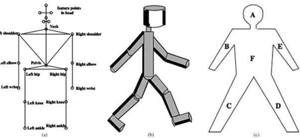
The first one is based on the segments of the human body and uses stick-figures, cylinder or contours to emulate the body parts. The model based on stick-figures considers that the human body is divided in joints that are grouped in subparts (head, torso, hip, arms and legs)Chen(1992). The example present on fig. 2.2 image A exemplifies this model and has 14 joints and 17 segments. The model in which the body is divided in cylinders is based on the Walker model. This model defines local Cartesian coordinate systems for each major articulation of the human body in order to facilitate the definition of the cylinders Hogg (1983). An example of this model is present on fig. 2.2 image B. The last model creates contours by means of ribbons. These ribbons are commonly used to represent 2D shapes and are abstract regions drawn from the outlined picture. These ribbons are then separated in two sets, one set for the parts of the human body and the other for the background aroud the body partsLeung(1995). On fig. 2.2 image c you can see this model only with the set of ribbons that represent the body parts.
2.2 Motion capture technologies 9
The second is based on the knowledge of how our eyes perceive motion. Studies show that human movement can be addressed by points representations or body contours without even as-suming any a priori relative stiffness or joint biomechanics of the points or corresponding borders Johansson (1976). Consequently, some methods based on this were created namely correlation measurements between points on the body, demand for fixed rotation axes of joint points, iterative search of the joints through the movement it is being extracted or based on analysis of the optical flow between successive imagesVilas-Boas and Cunha(2016).
The tracking process is used for establishing a correlation between the features extracted from the scene and the different frames of the movement and is based on ballistic trajectories or Kalman filters to predict the tracking object position, or use Mean-Shift inspired implementations such as the popular “Continuous Adaptive Mean Shift” (CAMSHIFT)Vilas-Boas and Cunha(2016). The number of cameras used for tracking plays a major role in having the best results and usually multiple cameras are only necessary when 3D imaging is necessary.
Recognition is usually associated with face recognition but it is also important in the identifi-cation of certain processes like frontal or backward movement. The algorithms for recognition that are used to identify these kinds of movements are based on phase space theory, motion dynamics constraints, and pattern recognition techniquesVilas-Boas and Cunha(2016).
2.2.2 Background of motion capture systems
The motion capture systems provide the data for the algorithms previously mentioned and are classified based on the sensors used and on the source of the signal that is received by the systems. Motion capture systems can be divided in Inside-out (sensors are placed on the body to detect natural or artificial external source), Inside-in (sensors and the sources are placed on the human body), Outside-in (external sensors that detect artificial or natural sources attached to the body) and Outside-out (computer vision based system). Another parameter that differentiates motion capture systems is the input signal of the sensors used which will determine the nature of the data recorded that can provide, for example, muscle activity information or inter-limb coordination. This new parameter can further classify motion capture systems as inertial, acoustic, mechanical, magnetic, optical and computer-vision based. Each of these systems belong to one of the classes previously mentioned in this sectionVilas-Boas and Cunha(2016).
Inertial systems belong to the Inside-in class that utilise on-body sensors (gyroscopes, ac-celerometers and magnetometers) that are used to measure many kinematic components of mo-tion. Gyroscopes measure the angular velocity of the of the body part to which it is attached. There are three types of gyroscopes from which the vibrating mass gyroscope was one of the most popular due to its lower size and weight compared to its peersGrimaldi and Manto(2010). The accelerometers however, uses Newtons second law as basis to measure the acceleration along the sensitive axis of the sensorGrimaldi and Manto(2010). The reliability of the accelerometers made it possible for them to be used within clinical context namely in analysing patients with PD. These systems were very disadvantageous in the past due to the big exoskeleton that was necessary to be
10 State of the art
used by the user and the difficulty of calibration. Nowadays it has evolved to the point that it can be used outside of a laboratory environmentVilas-Boas and Cunha(2016).
Acoustic systems can be Outside-in or Inside-out and are tracking systems that use ultrasonic pulses to determine the position of the body. The signal can be easily disturbed so unless there is a clear line of sight, this system should not be usedVilas-Boas and Cunha(2016).
Magnetic systems use magnetic field theory to produce 3D positions of the human body and rotational information. This is an Outside-in system that doesn’t cause any problem to the human body but can be easily disrupted by any electric or magnetic interferences in the surroundings Vilas-Boas and Cunha(2016).Another problem that comes with these systems is the fact that they are expensive and low accuracy. On the bright side, these systems do not suffer from any occlusion problems because the human body is transparent to magnetic fieldsGabriel et al.(1996). On fig. 2.3 you can see an example of an inertial and magnetic human motion tracking sensor.
Figure 2.3: Human motion tracking system using inertial and magnetic sensorsRoetenberg et al. (2009)
Mechanical systems are Inside-in systems and they make use of an exoskeleton to directly track body joint angles using the attached sensors, which provide occlusion free information of body posture Vilas-Boas and Cunha (2016). There are some good examples of these types of sensors namely the plantar pressure assessment that provides information about the foot and ankle functions during gaitOrlin and McPoil(2000);Abdul Razak et al.(2012).
Video recordings have been present for a long time in medicine and the diagnosis of many diseases is made by observation of those recording. However, without a quantitative analysis of the data recorded, this method is purely qualitative and dependent on the observation skill of the doctor. So the optical systems were created to improve this technique. These systems are marker-based and are, therefore, part of the Outside-in class. The idea is to use either reflective
2.2 Motion capture technologies 11
or light-emitting markers that are identified by the cameras and are used to recreate a 2D or 3D image (dependent on the number of cameras) of the movement captured. These systems have some difficulties attached, namely the calibration, post-processing time, non-portability and problems related to occlusionVilas-Boas and Cunha(2016).
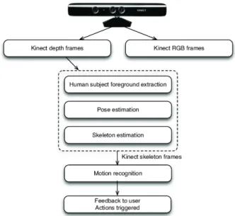
Finally, we have the marker-less Outside-out new systems that can reliably measure a wide range of parameters from human motion such as 3D body shape and disambiguate poses. These systems are commonly known as Computer vision based systems. A good example of the uti-lization of this new technology is the RGB-D cameras that have already been tested on the field and are giving very good results. A study has been made that uses the capabilities of the RGB-D camera to study epileptic seizure of a patient by monitoring his bed 24/7Cunha et al.(2016). As it was said before, this technology, without the usage of any kind of other sensors, was able to extract body motion information 87.5% faster and the images acquired had an average correla-tion with 3D mocorrela-tion trajectories of 84,2%. These systems can be divided based on the way they construct the 3D image. We have time of flight (ToF), which measures the depth of a scene by quantifying the changes that an emitted light signal encounters when it bounces back from objects in the scene, and structured-light (SL) systems, which the working principle is the projection, into the 3D scene, of a known light pattern viewed by the cameraVilas-Boas and Cunha(2016). An example of the architecture of these kinds of systems can be scene on fig. 2.4, in which a kinect camera is viewed and the steps of the recognition process is depict.
12 State of the art
2.2.3 Motion capture systems in clinical environments
The motion capture systems have suffered tremendous improvement through the years especially when related to the medical field. At the moment there are many systems used to study and diagnose epileptic seizures and the PD that use the capabilities of RGB-D cameras and the Kinect V1 and V2 to better capture the images that would then be analysed with the help of other medical means of examinationCunha et al.(2016).
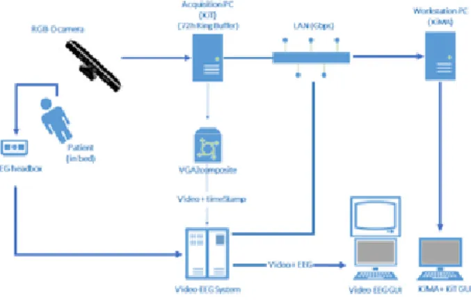
The first system worth mentioning and analysed is the NeuroKinect employed on the detection of epileptic seizures that was developed and used in the University of MunichCunha et al.(2016), INESC TEC and the Institute of Electronics and Informatics Engineering of Aveiro (IEETA). This system operates with an RGB-D camera (Microsoft Kinect), that sends the information to a computer running a KiT (software developed using the Kinect Software Development Kit v1.5) and is synchronized with an electroencephalogram (EEG) video system to acquire the data of the patientCunha et al.(2016). The editing, storage and analyse of the data are done using the KiMA software (the architecture of the system can be seen on fig. 2). This system can provide sets of motions of interest which allow the discrimination between seizures arising from temporal and extra-temporal brain areasCunha et al.(2016) which is crucial to the differentiation between seizures and therefore contributing for a better diagnose of this disease. Another important detail is that this system provides 3D imaging analyses which is a step forward compared to the original 2D imaging which is usually used in the clinical context.
Figure 2.5: NeuroKinect architecture
There are also motion capture systems used to study PD and two of them are systems based on a Kinect V1 RGB-D camera and the kinect V2. The process to acquire data is very similar to the one used in epileptic seizures, in which the KiT is used to acquire the skeleton data of the patient. The data acquired need to be manually selected since the camera as a particular range in which it works better and then the gait cycles are identified. This is done based on the depth information that is received at the same time as the skeleton is acquired (Schema on fig. 3). After this process many parameters are computed (velocity, accelerations, distances ...) for each gait
2.3 Kinect evolution 13
cycle and they are then used to distinguish between non-PD patients and PD patientsRocha et al. (2014). The second generation (Kinect V2) however, due to the new capabilities of the camera, such as, higher depth fidelity, infrared capabilities and the possibility to track more joints, made it more appropriate for the assessment of PD. One of the reasons is that it permits the usage of more gait parameters important for the diagnosis of PD. Finally it is important to say that this new system as an advantage over the old kinect V1 because it is more adaptable to new and different scenariosRocha et al.(2015).
Figure 2.6: Setup used for data acquisition using Kinect V1
2.3
Kinect evolution
For the scope of this dissertation, we will focus on the RGB-D cameras that were developed by Microsoft. The reason why this is so is because this thesis is focused on the works done in the fields of PD and Epileptic seizures in the hospitals of Porto and Munich that previously used the Kinect V1 and after that the Kinect V2. Therefore this section will focus on the evolution of this cameras until the Kinect V2 camera.
2.3.1 Kinect from XBOX 360
The first Kinect was made by Prime Sense in collaboration with Microsoft and came with the gaming platform XBOX 360, own by Microsoft, as a peripheral device. This Kinect was equipped with with a RGB camera and an IR emitter and camera Cruz (2012). An image of the Kinect can be viewed on fig. 2.7. These two cameras made it possible to acquire complementary color images and depth information per pixel of the image, which brought many advantages in the fields of computer graphics, image processing, computer vision and so on. An example of the usage of this camera in computer vision and image processing is using it to identify peoples by their faces named Kinect Identity. This technology was developed for the XBOX 360 and with time it learns the faces of the players so that it can identify who is the player 1 and 2 during games by their faces Leyvand(2011). Within medical context there are also studies conducted using this camera that proved to be very successful such as a respiratory monitoring system using the Kinect (Xia and
14 State of the art
Siochi(2012)) and also a sleep monitoring system that uses the depth information provided by the Kinect to detect sleep eventsYang(2014).
The great advancement of this new camera was the technology behind the depth sensor (IR emitter and camera), which was developed by group of researchers from Prime Sense (Zalevsky et al. (2013)). This sensor used the structured light method to measure the depth Cruz(2012), which was already explained in the section2.2.2. Due to the increase in popularity of this Kinect for the XBOX 360, a version for Windows was later released for developers and researchers to use Cruz(2012). The resolution and other characteristics of this Kinect can be viewed in fig. 2.9 in comparison to its successor the Kinect V2.
Figure 2.7: Kinect device and chipCruz(2012)
2.3.2 Kinect V2
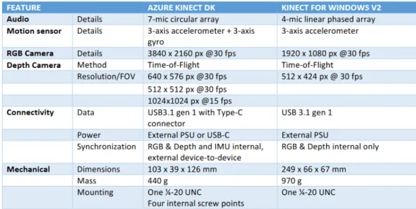
The second generation of the Kinect was the Kinect V2 which had some improvements in compar-ison to the previous version and also a major difference in the way the depth is measured. These advantages come in the form of better performance and accuracy, as well as a wider field of view due to this new way to measure depthAl-Naji et al.(2017). In Kinect V2 the depth is calculated using the ToF tecnhology that was described on the section2.2.2of this chapter. A study has been made that compares the two technologies (ToF and SL) using the Kinect V2 and the Kinect and explains in which environments each technology works betterSarbolandi(2015). In fig. 2.8 you can see the major differences between the two Kinects. As you can see, Kinect V2 has a wider field of view and better resolution for both the RGB camera and IR camera without lowering the frames per second (fps). Another thing worth notice is the increase in the number of joints that can be defined and the maximum number of skeletal tracking in the Kinect V2..
This Kinect comes equipped with an RGB camera, an IR sensor and projector that provide three types of frames, color, ir and depth. Besides these frames the Kinect V2 comes also equipped with a body tracking software that can reconstruct a 3D body and provide skeletal tracking, joint
2.3 Kinect evolution 15
Figure 2.8: Specifications comparison between Microsoft Kinect V1 and Kinect V2Al-Naji et al. (2017)
tracking and human recognition using the depth and color frames as basisAl-Naji et al.(2017). Overall the Kinect V2 is a better, more robust, version of the Kinect from Microsoft. Kinect V2 can be seen on fig. 2.9.
Figure 2.9: Kinect V2 sensorAl-Naji et al.(2017)
As mentioned in section2.2.2the application KiT was firstly programmed for the first version of the Kinect but later adapted to be used with the Kinect V2. This application reads the infor-mation from the Kinect and separates each of the frames (color, depth and IR) in different files to be further processed by the other software (KiMA and KiSA). The KiT also has a mode for gait analysis which retrieves the joints and skeletal tracking of the person being analysed.
16 State of the art
2.3.3 Azure Kinect
The last instalment of the Kinect series is the Azure Kinect. And as you can see in fig. 2.10 the new Azure Kinect was downsized and it is much more practical. The features of the camera are also present on the image.
Figure 2.10: Azure Kinect featuresTesych
The Azure Kinect made serious improvements in the depth camera by implementing the Am-plitude Modulated Continuous Wave (AMCW) ToF principle (Tesych) that is based on the paper published in 2018 that cover the continuous wave ToF principle. Cameras using this principle emit light with an amplitude modulated light source that is deflected when it encounters an object. The delay between the the emission of the light and the reflection is used to calculate distance between the camera and the object making it possible to create the depth imageBamji(2018). This camera gives two types of images, a depth-map and a clean IR reading (which the result depends on the amount of light on the scene). The capabilities of the camera are quite good with 1-Megapixel ToF imaging chip with advanced pixel technology which enables higher modulation frequencies and depth precision, automatic per pixel gain selection enabling large dynamic range allowing near and far objects to be captured cleanly and low systematic and random errors. It’s important to notice that all modes can be run at up to 30 fps with exception of the Wide Field of View (WFOV) unbinned mode that runs at a maximum frame rate of 15 fpsTesych.
The differences between the Kinect V2 and the Azure Kinect are quite significant, as you can see in fig. 2.11. The Audio and Motion sensors have been improved and a gyroscope was added. However for the scope of this thesis only the RGB and Depth camera are the one’s that need to be looked at. Focusing on the RGB camera it can be seen the the max resolution was improved and the fps are still 30. It’s important to note that this is not the only resolution available, as it will be shown on chapter3. The same goes for the depth camera in which it can be notice that 1024*1024 resolution only with 15 or less fps. This mode corresponds to the WFOV unbinned mode that was mentioned above. These are the main differences and what will be the focus of this thesis.
2.3 Kinect evolution 17
Chapter 3
Azure Kinect and KiT
This chapter will be divided into two parts. The first part will have an in-depth analysis of the colour and depth camera to understand the conditions in which they work and what modes work better with each other. The second part will focus on the problems of the previous KiT as well as the compatibility with the Azure Kinect. Then the best modes of operation will be chosen in accordance to the specifications given by the Hospitals in which the KiT is currently functioning so that the best performance can be achieved. This study will result in deciding whether to update the old KiT so that it can work with the Azure Kinect, or make a new KiT specifically for the new camera and for the objective of this thesis.
3.1
Azure Kinect
This section will present an overview of the hardware capabilities of the Azure Kinect as well as the functionalities available within the software development kit (SDK) that comes with it.
3.1.1 Overview
As described in chapter 2 the Azure Kinect comes equipped with a color camera and a depth camera. The color camera has six native operating modes in which the images are produced directly by the camera. These operating modes produce color images in three formats: MJPEG, YUY2 and NV12. However, due to the fact that the YUY2 and NV12 formats only work for the lowest resolution, they won’t be addressed in this thesis. Besides these three formats, the Azure Kinect can also produce images in BGRA format but it needs the host CPU to convert the original image in MJPEG to this format Tesych (2019). So it is not a native mode. There is another problem that this format has that will be addressed in this chapter that will dismiss this format from the scope of this thesis. Another thing to take into account is that the mode with resolution 4096x3072 only achieves a frame rate of 15 which is not optimal to study neurological diseases in which the smallest detail can’t be overlooked. And if 30 fps is not achieved, some information
20 Azure Kinect and KiT
may be lost due to loss of frames. The characteristics of the color camera can be observed in fig. 3.1.
Figure 3.1: Native color operating modes of Azure KinectTesych(2019)
The depth camera also has different modes of operation. They can be divided in three groups: narrow field of view (NFOV), wide field of view (WFOV) and Passive IR. For this project, Passive IR will be dismissed since this mode turns of the iluminators of the camera and depends only on the ambient illumination of the space in which the camera is instaled. Another distinction between the modes is that both the NFOV and WFOV modes can be binned or unbinned. The binned modes are less precise then the other modes because the reduce the resolution of the images by combining two adjacent pixels into one bin. Like the color camera high resolution mode, the depth camera also has a mode that can only achieve 15 fps (WFOV unbinned) so it will be discarded for this project due to the same reason mention on the previous paragraph. The last thing to notice is the field of interest (FOI) that is way bigger in the WFOV mode. These modes and their characteristics can be seen on fig. 3.2.
Figure 3.2: Depth operating modes of Azure KinectTesych(2019)
The only thing that is missing is understanding how the fields of view (FOV) of both cameras are positioned depending on the modes selected. In fig 3.3 a representation of the FOV of the
3.1 Azure Kinect 21
cameras can be observed. From the observation it can be seen that the WFOV mode is not that compatible with this project since there is a need for a good overlap of pixels between the color and depth images. From this point of view the best option would be a NFOV unbinned mode with a color camera mode with an aspect ratio of 4:3 for better overlap between images, better resolution and precision. However, a color camera mode with aspect ratio of 16:9 can’t be overlooked since the overlap is only bad on the corners of the images. And those corners are usually discarded on the processing part done by the KiMA and KiSA applications.
Figure 3.3: FOV of color and depth camerasTesych(2019)
3.1.2 Azure Kinect SDK
The Azure Kinect comes equipped with a couple of tools and a SDK. The tools encompass a viewer, that lets you play a previously recorder file and can also show the images captured by the camera in real time, a recorder, that lets you record the type of images that you want with the format you choose, and a firmware tool to update your system.
The Azure Kinect SDK is the software provided by Microsoft that gives you access to the device configurations and the the hardware of the sensors so that you can develop your own code for the Azure Kinect. This version has some major differences compared to the previous version. In the Kinect V2 SDK you had access to the color and depth frames, as well as the body tracking frames in the same function. Basically you had one function two access both parts and it would provide synchronised frames. Now, the Azure Kinect SDK, separated these in two SDKs, the Sen-sor SDK and the Body Tracking SDK. Therefore, obtaining synchronised frames of both parts is more complicated. However, the color, depth and IR frames can still be obtained in a synchronised way. For the scope of this thesis the focus will be on the Sensor SDK.
The Sensor SDK has many core functionalities that are related with the hardware that com-poses the Azure Kinect. The cameras provide the images that can then be accessed by the SDK and can also be either transformed or saved. The Inertil Measurement Unit (UMI) can be accessed
22 Azure Kinect and KiT
to get the samples related to the motion of the device provided by the accelerometer and the gy-roscope. And the microphones can also be accessed. But what really matters in this project is the images acquired by the cameras. With the Sensor SDK we can change the color format and resolution, change the depth mode, select the frame rate, retrieve only the synchronised frames and even manage many Azure Kinects at the same time. This last function won’t be addressed in this project. One interesting feature of this SDK is that it lets you transform the depth image into the color image and vice versa. This way you can have, for example, two images with the same dimensions in which one is a simple color image and the other is the transformation of the depth image into the color image. The last feature, and one that will also be used on this project, is the possibility to record the three images in a matroska file video (mkv) file. This file will contain instances of each type of image, with additional information beyond the image. It will save also the width, height, size, data stamp and other useful information. The file can be opened with a normal video player and you will see only the color video but if you use the viewer tool you can see the three frames in video. However, there is one color format that is not supported by this recorder function, the BGRA format. The thing that makes this function powerful is the fact the you also have access to a playback function that loads the mkv files and gives you access to the instances of the images and all the information within. This will prove crucial for this project.
3.2
The KiT decision
In this section a simple review of the key concepts behind the KiT will be presented in order to better understand how the Azure Kinect can be integrated (or not) into the code and also the circumstances of the Hospitals in which the KiT is integrated. After that simple preliminary test was made to see how the camera worked using different combinations of the color camera and depth camera modes to see which one should be used in the environment that the KiT is placed. In the end it will be decided whether to continue using the original KiT or make a new one.
3.2.1 The KiT and the hospital environment
The KiT is an application that connects to the Kinect hardware, reads the information provided be it and then export it to specific files that can be later processed by other software applications like KiMA and KiSA, so that it can help analyse and diagnose neurological diseases. If we use the terms presented in the chapter2, the KiT belongs to the extraction part of the motion capture algorithm. However this application also has some tracking process since it accesses the body tracking module of the Kinect V2 to extract the body skeleton and joint for further processing. For this project the focus will be on the extraction of the images and their exportation to files.
The flow of the application is pretty easy to understand. In order to start acquiring the frames, the application should receive some input from the user. First comes the information related to where to save the frames and the name of the session. Next you should select in the preferences
3.2 The KiT decision 23
the frames that you would like to save. It can be any combination between color, IR, depth, body and/or body index frames. Finally you have the option to select which frames you want to see while acquiring. This way you can keep track of what is being acquired at the same time that it is done. After receiving all this input the application can start acquiring the data. As mentioned in the previous section, the Kinect V2 provides all the frames in a multi frame reader so the KiT just saves each frame in a queue of their own to be dealt in a different thread each. Each frame that is acquired can be shown in the KiT interface and saved in the correspondent file that will be exported for processing in other applications. The input that the user made at the beginning is responsible for selecting the frames saved and shown on the interface. The frames shown can be selected while the camera is acquiring as shown on fig. 3.4. This figure is an image of the KiT working in the University of Munich Epilepsy Monitoring Unit (EMU) and is actually showing the skeletal body image acquired from the Kinect V2. As you can see by the image, the body tracking software of the Kinect V2 is not very precise because the woman has her left arm up, but the left arm of the skeleton is not. These are the main concepts behind the KiT software.
Figure 3.4: KiT operating inside the University of Munich EMUCunha et al.(2016)
The KiT application is not only being used in the epilepsy unit functioning but also in a PD unit in the São João University Hospital in Porto (Portugal) that also implements this application. In both cases the KiT was introduced to help the analysis of the diseases. The previous examinations that were done by the doctors continue to exist and the KiT just provides new information to the system. The idea that is used is that when a seizure is identified by the exams, the doctor can use the information captured by the KiT in that moment and compare it with their own exams. This information that was captured by the KiT was processed by the KiMA or KiSA software
24 Azure Kinect and KiT
in order to be used. In fig. 3.5 we can se the EMU system functioning in which the EEG that detects seizures is compared to the images acquired by the KiT after being synchronised. The most important factor for the KiT to function correctly in these environments is to know the space available for saving all this information acquired. The KiT has access to a buffer of 10 TB of data for saving purposes. This is important for the tests conducted using the Azure Kinect in the next section, because it will help to decide the best approach for the KiT application.
Figure 3.5: Aspects of the 3Dvideo-EEG system console installed in the routine of University of Munich EMUCunha et al.(2016)
3.2.2 Azure Kinect Mode Preliminary Tests
The test done to the Azure Kinect is supposed to test the real frame rate acquired by the device in the different modes, as well as see the space occupied in disk by the images provided by the device. After getting the images a calculation using the 10 TB of memory available in the hospitals to get the time that the Kit can be functioning without running out of space. This preliminary test is a simple program in C that has the following flow:
• Start the Azure Kinect Device
• Configure the device to the mode being tested • Start the cameras
3.2 The KiT decision 25
• Save the images in files
This program was made using the C language since the source code of the Azure Kinect SDK is also written in C. This program is very standard and uses just the functionalities of the SDK for starting the devices and cameras with the correct configurations. As an example, if you want to configure the device to work at 30 fps, use the color format MJPEG with a resolution of 1280*720 and the depth mode NFOV Unbinned, you should do the following:
1 k4a_device_configuration_t config = K4A_DEVICE_CONFIG_INIT_DISABLE_ALL; 2 config.camera_fps = K4A_FRAMES_PER_SECOND_30;
3 config.color_format = K4A_IMAGE_FORMAT_COLOR_MJPG;
4 config.color_resolution = K4A_COLOR_RESOLUTION_720P; 5 config.depth_mode = K4A_DEPTH_MODE_NFOV_UNBINNED; 6 config.synchronized_images_only = true;
Listing 3.1: Azure Kinect device configuration in C
The last configuration makes it only possible to receive synchronised images from the device. This being said, there were some configurations that were left out due to certain reasons. For the color format, only the MJPEG and BGRA formats were tested since the other two (YUY2 and NV12) only worked in the lowest resolution. The color resolution 4096x3072 was also left out of the test because it only worked at a maximum of 15 fps. The depth mode WFOV Unbinned was also not tested because of the same fps issue. The test was divided in two parts, one centered around the color format MJPEG and the other on the BGRA format, because these formats were the cause of the major differences in the frame rate of the device.
In the fig. 3.6 you can see the test results for the color format MJPEG. Looking into the results it can be seen that in this format the fps is very close to the 30 that was expected and only when the device was configured to the resolution that used the aspect ratio 4:3 would the value be slightly lower. The test also showed what was the configuration that had the best duration and the one with the worst. These durations were obtained by calculating the amount of images that could be saved on the entire 10TB disk and based on the frames per second obtained by each configuration. The best duration was achieved with the 720p color resolution and the NFOV 2x2 Binned depth mode. The worst duration was the 2160p resolution and the NFOV Unbinned depth mode.
The BGRA color format test results can be observed in the fig. 3.7. The results of this format were a very different from the previous. The fps in this mode was lower then 30, even if not by a great margin, and the resolution with aspect ratio of 4:3 was closer to the 15 fps mark than the 30. This result may be caused by the fact that BGRA images are converted from the MJPEG native format provided by the device. This means that before the images are acquired, the host CPU processes the original images in order to provide the BGRA images, which causes the fps to be lower. Another problem with this format is the size of the files. As it can be seen in the image, the size of the color images is so big that even in the lowest resolution, the KiT can only work for a day without running out of space.
26 Azure Kinect and KiT
Figure 3.6: Depth operating modes of Azure KinectTesych(2019)
Figure 3.7: Depth operating modes of Azure KinectTesych(2019)
3.2.3 The KiT problems and the decision
There is one last thing to consider before making a decision regarding the KiT and the Azure Kinect, the current problems that the KiT has, which are:
• The frame rate of the application drops from time to time which causes loss of important information
• The files in which the frames are saved (binary files) have some issues that cause the infor-mation to be sometimes rewritten and as a result, loss of inforinfor-mation
• The format in which the information is save is very complicated, which causes difficulties in reading the data in the KiMA and KiSA software.
These problems were identified through the years of utilization of the application by the su-pervisor of this thesis, and by a Machine Learning Researcher at INESCTEC. In view of all the
3.2 The KiT decision 27
information gathered in the previous sections and chapters, and with the information regarding the problems of the KiT decisions have been made.
The first decision made was to create a new KiT for acquiring the color, depth and IR frames. This decision was made due to two key factors. The loss of valuable data due to frame rate drops and and the binary files and also due to the new feature of the Azure Kinect SDK that lets you record the captures directly from the camera without frame drops. This last reason was also the one that molded the new KiT. Basically, to correct the frame drops, it was decided that the new KiT will be divided in two parts, or better said, two distinct applications. One part will just produce the recording video and show it in real time to the user, so that the program won’t lose processing time with saving each image into files and all the additional information that caused the frame drops. The second part will open the video file (mkv file) using the Azure Kinect SDK and will seperate each type of frames (color, depth and IR) into separate files and create an additional file with the complementary information regarding each frame.
The Second decision was related to the main configuration that would be used for the device. Looking into the color format, the MJPEG format was chosen for three reasons. The size of the files were more appropriate since more then one day would be preferable. The frame rate is much more stable than the BGRA format. But the most important reason is that the BGRA format is not supported by the recording function of the SDK because it is not a native mode of the Azure Kinect. The depth mode selected was the NFOV Unbinned manly because the other two modes were binned and lost half of the information as mentioned in the beginning of this chapter. Therefore the depth and IR images acquired have better resolution which is great for the processing done by KiMA and KiSA. The last configuration chosen was the 720p color resolution so that the KiT could function nonstop for more than two days without running out of space. This configuration corresponds to the test V6 in the fig. 3.6.
These were the decisions made with the information gathered on the last chapters. In the next chapter the development methods applied in the making of the Azure KiT will be discussed.
Chapter 4
Azure KiT development
This chapter will be divided in three parts that will explain the process of development of the Azure KiT and also the programming language and tools used in the development. The first section will describe the tools and the other two sections will explain the development of each part of the KiT. The last section will present the system architecture of the application developed.
4.1
Development tools
The programming language chosen for this project was C], which is a multi-paradigm program-ming language, using the WPF (Windows Presentation Foundation) framework. This combination was chosen for two reasons. The previous KiT was already made using this technology and it provided a good graphic interface for the user. And also because a library in C] for the SDK was already made and the functionalities needed for the project were available.
To use C] and the WPF framework, the IDE (integrated development environment) Visual Studio was chosen, because all three technologies were developed by Microsoft making it easier to use and get support when needed.
In addition to these technologies three nuget packages belonging to the NuGet Gallery were used. The NuGet Gallery is a package manager for .Net and it gives access to many libraries with useful functionsNuGetGallery(2020). The first nuget package that was used was the K4AdotNet package which is a library that provides the functions to work with the Azure Kinect devices using C]bibigone and baSSiLL(2020). Another package used was the Extended.Wpf.Toolkit that pro-vides many WPF controls that are not present on the original frameworkXceed(2020). The last package used was the Accord.Video.FFMPEG.x64 which contains a bundle of classes and meth-ods to handle video files using FFMPEGAccord.NET(2017). This last package was specifically for 64 bit applications because the Azure Kinect SDK doesn’t work with 32 bit applications.
30 Azure KiT development
4.2
Azure Kit part 1
In this section, the process of development of the first part of the Azure KiT will be presented, starting with the definition of the requirements for the application followed by the mockups of the user interface and the development process of the program.
4.2.1 Requirements and Mockups
The definition of the requirements for this part of the KiT was agreed upon by the candidate and the supervisor. The main focus of this part of the KiT was to provide a clear interface to the users and to correctly produce the mkv file with the color, depth and IR frames. The requirements were divided in three groups one for each simple window interface that the user had access. The windows are: initial window for the definition of the session, main window for the recording and a configuration window to let the user change the device configurations if needed. The requirements are as follows:
1. Initial Window
• Get the folder in which the user wants to save the mkv file
• Get the name of the session in order to separate from other sections that may have already been recorded in the same folder or even to save on the same session if the user wants it so.
• Start the session and move to the main window 2. Main Window
• The main window should have a screen to show the color image at the same time that it is being recorded
• While being recorded the user should know that the images are getting acquired • The video recorded should be split in 2 minutes videos to facilitate the access to the
videos in the times of the day needed and to not loose all the content if the Kit stops working.
• A button to start the recording • A button to stop the recording
• A button to get access to the configurations window 3. Configurations Window
• Let the user select the color format • Let the user select the color resolution
4.2 Azure Kit part 1 31
• Let the user select the depth mode • Let the user select the frame rate
• Let the user select the duration of the videos recorded • Let the user confirm the selected options
Mockups were made for each of these windows. In fig. 4.1 the mockup for the initial window is presented. As it can be seen the user can select the folder and the name of the session before starting it.
Figure 4.1: Mockup of the initial window of the Azure KiT
The main window can be observed in fig. 4.2. In the mockup you can see the screen that will show the real time color image and the buttons for the functions required in the requirements.
32 Azure KiT development
The configurations window can be observed in fig. 4.3. The configuration window gives the user the option to change the configurations as demanded by the requirements as well as a button to confirm the new configurations.
Figure 4.3: Mockup of the configurations window of the Azure KiT
4.2.2 Development Process
Having defined the requirements and mockups the development process of the program can be started. The first thing to look at when programming with the WPF framework is that you have windows that communicate between themselves and that contain elements that can have events associated. So the first thing developed was the layout of the three windows with the elements that were defined in the previous section. After this, the events for each element were created and the link between the windows was established.
In this part of the Azure Kit the main window was the core window, so it was the one that called the other windows. When the program starts the main window calls the initial window with the dispatcher and is hidden until the initial window ends the work it is supposed to do.
The work that the initial window needs to do is pretty simple, it just needs to select or create a new folder (if it doesn’t exist yet) for the images to be saved in. The code that is shown on the listing 4.1 is what is used in the initial window.
1 // Create a Folder Browser
2 String folderName = null;
3 WinForms.FolderBrowserDialog dlg = null; 4 dlg = new WinForms.FolderBrowserDialog();
4.2 Azure Kit part 1 33
5 dlg.SelectedPath = System.AppDomain.CurrentDomain.BaseDirectory; 6
7 // Show open file dialog box
8 WinForms.DialogResult showResult = dlg.ShowDialog(); 9
10 // Check if the directory exists 11 !Directory.Exists(folderName)
12
13 // Creates a new directory if it doesn’t 14 Directory.CreateDirectory(folderName); 15
16 // Saves the name of the directory if it exist and can be opened 17 Directory.GetAccessControl(folderName);
Listing 4.1: Select the folder where the recording files are saved
After the initial window was completed the main window became the focus of the develop-ment. And this is where the K4AdotNet package. As mentioned before, this package provides the same functions that the Azure Kinect SDK provides but in C] language. When the main window is loading, the Kinect device is opened and configured with the modes chosen on the chapter3. Next the recording event was made. This event would be activated when the user clicked on the record button. This event can be broken down in three main activities. The first activity was creating the recording file using the SDK functions, to where the captures obtained by the Kinect will be recorded. The second part was creating an event that would trigger when the 2 minutes (unless another video duration was selected) have passed in order to create a new recording file. The video division purpose is to make sure that the data being acquired is saved and not lost. If the data was being saved in only one file and the application stopped working due two external reasons or lack of this space, all the information might get lost. This way if it happens only the file being used at the time is lost. A sample of this second activity can be seen on the listing 4.2.
1 // Create a timer for 2 minutes
2 Timer saveTimer = new Timer(1000 * 2 * 60); 3
4 // Generate the event
5 saveTimer.Elapsed += saveTimer_Elapsed; 6 saveTimer.Start();
7
8 // Event function
9 private void saveTimer_Elapsed(object sender, ElapsedEventArgs e)
10 {
11 // File name has the day an time
12 currentDate = DateTime.Now;
13 this.file_name = this.folderName + "/" + currentDate.ToString("
34 Azure KiT development
14 // Create the new file with the SDK functions
15 this.recorder[this.recorder_counter + 1] = new Recorder(this.file_name
, this.device, this.config);
16 this.recorder[this.recorder_counter + 1].WriteHeader(); 17 this.recorder_counter++;
18 this.recorder[this.recorder_counter - 1].Dispose(); 19 }
Listing 4.2: Timer and event responsible for the creation of the recording files
The last activity is receiving each capture, show the color frame on the screen and save the captures to the file. receiving the capture can be done using the nuget package that it is being used. To show the color image the buffer of the color image (that contains the raw image data) needs to be transformed into a bitmap source to be then shown on the screen. In listing 4.3 is the sample of the code responsible for showing the image on the screen. Note that this is not the only way to show an image from the image buffer. After showing the color image the full capture can be saved and disposed to give space to the next capture.
1 // Verify if the color image was obtained 2 if (capture.ColorImage != null)
3 {
4 // Create an intermediate byte array buffer to save the image 5 var color = capture.ColorImage;
6 innerBuffer1 = new byte[color.SizeBytes];
7 Marshal.Copy(color.Buffer, innerBuffer1, 0, innerBuffer1.Length); 8
9 // Create and show the bitmap source
10 using (var stream = new MemoryStream(innerBuffer1)) 11 {
12 colorImageKinect.Source = BitmapFrame.Create(stream,
BitmapCreateOptions.None,BitmapCacheOption.OnLoad);
13 } 14 }
Listing 4.3: Show the color image on the screen
Only the configuration is left and this one has a very simple job. It only receives the input of the user related to the configurations of the device and changes it if the user confirms it. With this the Azure KiT part one is completed and the next part can be addressed.