Repositório ISCTE-IUL
Deposited in Repositório ISCTE-IUL:
2018-12-04Deposited version:
Post-printPeer-review status of attached file:
Peer-reviewedCitation for published item:
Conti, C., Soares, L. D. & Nunes, P. (2018). Scalable light field coding with support for region of interest enhancement. In 2018 26th European Signal Processing Conference (EUSIPCO). (pp. 1869-1873). Roma: IEEE.
Further information on publisher's website:
10.23919/EUSIPCO.2018.8553608Publisher's copyright statement:
This is the peer reviewed version of the following article: Conti, C., Soares, L. D. & Nunes, P. (2018). Scalable light field coding with support for region of interest enhancement. In 2018 26th European Signal Processing Conference (EUSIPCO). (pp. 1869-1873). Roma: IEEE., which has been published in final form at https://dx.doi.org/10.23919/EUSIPCO.2018.8553608. This article may be used for non-commercial purposes in accordance with the Publisher's Terms and Conditions for self-archiving.
Use policy
Creative Commons CC BY 4.0
The full-text may be used and/or reproduced, and given to third parties in any format or medium, without prior permission or charge, for personal research or study, educational, or not-for-profit purposes provided that:
• a full bibliographic reference is made to the original source • a link is made to the metadata record in the Repository • the full-text is not changed in any way
The full-text must not be sold in any format or medium without the formal permission of the copyright holders.
Serviços de Informação e Documentação, Instituto Universitário de Lisboa (ISCTE-IUL) Av. das Forças Armadas, Edifício II, 1649-026 Lisboa Portugal
Phone: +(351) 217 903 024 | e-mail: [email protected] https://repositorio.iscte-iul.pt
Scalable Light Field Coding with Support for Region
of Interest Enhancement
Caroline Conti Instituto de Telecomunicações Instituto Universitário de Lisboa
(ISCTE-IUL) Lisbon, Portugal [email protected]
Luís Ducla Soares Instituto de Telecomunicações Instituto Universitário de Lisboa
(ISCTE-IUL) Lisbon, Portugal
Paulo Nunes
Instituto de Telecomunicações Instituto Universitário de Lisboa
(ISCTE-IUL) Lisbon, Portugal [email protected]
Abstract—Light field imaging based on microlens arrays – a.k.a. holoscopic, plenoptic, and integral imaging – has currently risen up as a feasible and prospective technology for future image and video applications. However, deploying actual light field applications will require identifying more powerful representation and coding solutions that support emerging manipulation and interaction functionalities. In this context, this paper proposes a novel scalable coding approach that supports a new type of scalability, referred to as Field of View (FOV) scalability, in which enhancement layers can correspond to regions of interest (ROI). The proposed scalable coding approach comprises a base layer compliant with the High Efficiency Video Coding (HEVC) standard, complemented by one or more enhancement layers that progressively allow richer versions of the same light field content in terms of content manipulation and interaction possibilities, for the whole scene or just for a given ROI. Experimental results show the advantages of the proposed scalable coding approach with ROI support to cater for users with different preferences/requirements in terms of interaction functionalities.
Keywords—light field, field of view scalability, region of interest, image compression, HEVC
I. INTRODUCTION
Recent advances in the manufacturing of optics and imaging sensors made it possible to have richer forms of visual data, where spatial information about three-dimensional (3D) scenes is represented in addition to angular viewing direction — the four-dimensional (4D) light field/radiance sampling [1].
In the context of Light Field (LF) imaging, the approach based on a single-tier camera with a Microlens Array (MLA) [2] (hereinafter referred simply to as LF camera) has become a promising approach with application in many different areas, such as 3D television [3], richer photography capturing [4], biometric recognition [5], and medical imaging [6].
To deal with the new challenges that need to be overcome for successfully introducing light field media applications into the consumer market, novel standardization initiatives are also emerging. Notably, the Joint Photographic Experts Group (JPEG) committee has launched the JPEG Pleno standardization initiative [7], and the Moving Picture Experts Group (MPEG) has recently started a new work item on coded representations
for immersive media (MPEG-I) [8]. The challenge to provide a LF representation with convenient spatial resolution and viewing angles requires handling a huge amount of data and, thus, efficient coding becomes of utmost importance. Another key requirement when designing an efficient LF representation and coding solution is to facilitate future interactive LF media applications supporting new manipulation functionalities. In this context, various LF coding solutions have already been proposed in the literature, achieving significant compression gains when compared to state-of-the-art 2D image coding solutions [9]–[12]. Still, transmitting the entire LF data without a scalable bitstream may represent a serious problem since the end-user needs to wait for the entire LF data to arrive before he/she can visualize and interact with the content.
One of the advantages of LF imaging is the ability to support manipulation functionalities not straightforwardly available in conventional imaging systems, namely: post-production refocusing, changing depth-of-field, and changing viewing perspective. With this in mind, the content creator can choose to organize differently the LF content to be sent to multiple end-users who may be using different display technologies, as well as applications, that allow different levels of interaction. Therefore, an efficient scalable LF coding architecture is desirable to accommodate in a single compressed bitstream a variety of sub-bitstreams appropriate for users with different preferences/requirements and various application scenarios.
With this objective, the concept of Field of View (FOV) scalability and a novel FOV Scalable Light Field Coding (FOVS-LFC) solution were proposed in [13]. By hierarchically organizing the angular information of the captured LF data, progressively richer forms of the same LF content are supported in higher layers of FOV scalability. More specifically, the base layer contains a subset of the LF raw data with narrower FOV, which can be used to render a 2D version of the content with very limited rendering capabilities. Following the base layer, one or more enhancement layers are defined to represent the necessary information to obtain more immersive LF visualization with a wider FOV. This means that, for instance, a user who wants to have a simple 2D visualization will only need to extract the base layer of the bitstream, thus reducing the necessary bitrate and the required decoding computational power. On the other hand, a user who wants a higher level of immersion or who wants to creatively decide how to interact This work was supported by FCT (Fundação para a Ciência e a Tecnologia,
with the LF content can promptly start visualizing and manipulating the LF content, by extracting only the adequate bitstream subsets (which fit in the available bitrate).
To better handle this type of application scenarios, the coding architecture proposed in [13] is here extended to enable easy support for Region of Interest (ROI) coding [14] in the enhancement layers. This will give the user the possibility of increasing the FOV only for an object or region of interest.
The remainder of this paper is organized as follows. Section II presents the concept of FOV scalability, which is important to understand what is discussed later in the paper. Section III describes the FOVS-LFC solution architecture with ROI support. Section IV presents the test conditions and experimental results illustrating this new type of LF functionality and, finally, Section V concludes the paper with a critical analysis of the proposed approach and some directions for future work.
II. FOVSCALABILITY CONCEPT
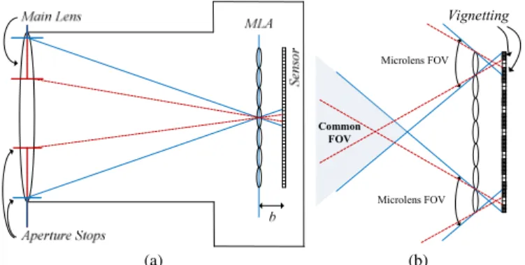
As seen in Fig. 1a, an LF camera consists of a main lens and an MLA placed at any distance of the image sensor. Therefore, in an LF camera, differently from a conventional 2D camera, each sensor element (hereinafter referred to as pixel) collects the light of a single ray (or of a thin bundle of rays) from a given angular direction θ,φ that converges on a specific microlens at position x,y in the array. The obtained image is known as the (raw) LF image.
The FOV of a lens (typically expressed by a measurement of area or angle) corresponds to the area of the scene over which objects can be reproduced by the lens. In a conventional 2D camera, the FOV is related to the lens focal length and the physical size of the sensor. In an LF camera, the microlens FOV is directly related to the aperture of the main lens. To illustrate this fact, Fig. 1a depicts the LF camera with two different aperture sizes (as shown by the blue and red aperture stops). As can be seen with the blue and the dashed red lines, all the rays coming from the focused subject will intersect at the MLA and will then diverge until they reach the image sensor. Moreover, comparing the blue lines with the dashed red ones (in Fig. 1a), it is possible to see that the main lens aperture (or more specifically, the F-number of the main lens) needs to be matched
to the F-number of the MLA to guarantee that the pixels behind each microlens, usually called a micro-image (MI), receive homogeneous illumination on their entire area, as seen in the blue line case (Fig. 1a). Otherwise, in the case of the dashed red line (Fig. 1a), pronounced vignetting will be visible in each MI. As depicted in Fig. 1b, the common area where the FOV of all microlenses overlaps can be seen as a measure of the amount of angular information in the captured LF content. When there is MI vignetting (see dashed red lines in Fig. 1b), the microlens FOV will be further restricted and, consequently, the angular information will be narrowed. This makes it possible to control the amount of angular information available in the captured LF content by adjusting the main lens aperture. This fact has motivated the FOV scalability concept presented in [13].
The basic idea of the FOV scalability is to split the LF raw data into hierarchical subsets with partial angular information. Generally speaking, the FOV scalability can be thought of as a virtual increase in the main lens aperture (see Fig. 2a) from one layer to the next higher layer, corresponding to a wider microlens FOV and less vignetting inside each MI (along its border).
A. LF Data Organization for FOV Scalability
By properly selecting subsets of pixels from each MI, it is possible to split the overall angular information available in the captured LF image. This is illustrated in Fig. 2 for a hypothetical case in which the angular information is split into three hierarchical layers. In each lower layer (from top to bottom in Fig. 2b), the microlenses FOV will be further restricted (see Fig. 2a) and, consequently, the available angular information of the LF content will be narrowed.
Due to the nature of the LF imaging technology, where angular θ,φ and spatial x,y information are spatially arranged in a 2D image (i.e., the LF image), the increased angular information in each higher FOV scalable layer implies also an increase in the resolution of the LF content in the layer.
(a) (b)
Fig. 1 LF camera: (a) Basic optical setup comprising a main lens and an MLA at any distance of the image sensor. In this example, → , where is the MLA focal length; (b) The FOV can be used as a measure of the overall angular information in the LF content. If main lens and MLA F-numbers are not adjusted, the FOV is restricted and MI vignetting is observed.
Vignetting Microlens FOV Common FOV Microlens FOV (a) (b)
Fig. 2 FOV Scalability concept with three layers: (a) Ray tracing diagram showing the three hierarchical layers corresponding to a virtual increase in the main lens aperture; and (b) From base layer (bottom) to the last enhancement layer (top), the FOV is wider and, consequently, the LF content resolution progressively grows as well.
B. Enabled FOV Scalability Functionalities
With the FOV scalability approach, new levels of scalability can be defined, for instance, in terms of the following rendering capabilities [13]: changing perspective, changing focus (refocusing) and varying depth-of-field.
Since narrowing the FOV of each MI will limit the angular information in lower layers, the number of different viewpoint perspectives that can be rendered will also decrease. This means that higher layers will have a wider range in which the perspective can be changed. The same happens for the ranges in which the focus and the depth-of-field can be varied, with higher layers having a wider range and lower layers having a narrower one.
III. PROPOSED FOVSARCHITECTURE WITH ROISUPPORT The FOV Scalable Light Field Coding architecture proposed in [13] can be extended to enable easy integration of ROI coding [14], [15]. ROI coding can be an important functionality, especially in limited bitrate network channels [15], and in application scenarios where some portions of the visualized content are of higher interest than others. In the FOV scalable data organization, this functionality would allow further flexibility in the bitstream for supporting the new LF interactive manipulation capabilities.
For instance, for an LF image with very large resolution, the size of the compressed bitstream may still be considerably large in lower LF enhancement layers to be streamed efficiently. Thus, a solution would be to send in these layers only a portion of the image which is of the most interest (i.e., the ROI) with wider FOV. Therefore, the end-user receives a coarse version (in terms of FOV) of the LF content in the base layer and, if needed/required a portion or portions of the coarse received LF content can be refined (in terms of FOV) by decoding further enhancement layers.
Fig. 3 illustrates this concept for a three layer scenario. In the base layer (bottom), a coarse version of the LF content is available with very restricted FOV. Following this, a first ROI enhancement layer is defined containing a foreground object (the same in Fig. 3a and Fig. 3b), for which the FOV is enhanced. In Fig. 3a, the highest ROI enhancement layer (top) considers the same ROI as the previous layer, but with an even wider FOV. Differently, in Fig. 3b, the highest ROI enhancement layer considers the same FOV as the previous layer but increases the ROI size. Both cases contain a similar amount of texture information in the highest layer.
A. FOVS-LFC Architecture with ROI Support
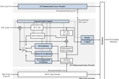
The proposed FOVS-LFC architecture with ROI support (see Fig. 4) is based on the architecture proposed [13]. The coding architecture is built upon a predictive and multi-layered approach. Its adaptation for supporting ROI coding in presented below.
The LF data is firstly organized into several layers, in which higher layers typically correspond to regions of the LF image with wider FOV. In this process, the content creator will select creatively the number of hierarchical layers and their characteristics, namely the size of the subset of pixels to be sampled, the area of the LF defining the ROI for that layer (see examples in Fig. 3) and, eventually, the associated visual quality level (see Section III.B). The decision of having narrower or wider angular information in each hierarchical layer can be made dependent on the application scenario. For example, the base layer can contain a sub-sampled portion of the LF data, which can be used to render a 2D version of the content with limited interaction capabilities (narrow FOV, limited in-focus planes, and shallow depth-of-field). As shown in Fig. 4, this base layer can be coded with a conventional HEVC intra encoder to provide backward compatibility with a state-of-the-art coding solution, and the reconstructed picture is used for coding the higher layers. Following the base layer, one or more enhancement layers (enhancement layers 1 to in Fig. 4) are defined to represent the necessary information to obtain more immersive LF visualization. Each higher enhancement layer picture contains progressively richer angular information, thus
(a) (b)
Fig. 3 FOV scalability examples with ROI enhancement layers – base layer (bottom), last enhancement layer (top); the amount of information gathered in each layer is depicted with proportional sizes: (a) The last ROI enhancement layer (top) considers the same ROI as the previous layer, but with wider FOV; (b) The last ROI enhancement layer (bottom) considers the same FOV as the previous layer but with a larger ROI.
Fig. 4 FOVS-LFC architecture (novel and modified blocks are highlighted in blue) in which one or more ROI enhancement layers (from 1 to N-1) are coded with the proposed LF enhancement layer encoder.
Decoded Picture Buffer
-HEVC Intra Encoder
FOV Scalable Bitstream Deblocking & SAO Filtering Inv. SQ / Inv. DCT Header Formatting & CABAC Intra Prediction
Base Layer Encoder
Direct IL Prediction
Reconstructed Enh. Layer 1
LF Enhancement Layer Encoder
Enh. Layer N
Enh. Layer 1
Base Layer (Layer 0)
LF Enhancement Layer Encoder
Reconstructed Base Layer Reconstructed Enh.Layer N-1
General Coder Control
DCT/ SQ
SS Prediction
IL Compensated Prediction
increasing the LF data manipulation flexibility. Finally, the last enhancement layer represents the additional information to support full LF visualization with maximum manipulation capabilities (as defined by the content creator). Each enhancement layer is encoded with the proposed LF enhancement layer codec seen in Fig. 4, which is based on the HEVC architecture and may explore spatial and inter-layer redundancy through self-similarity (SS) [11] and inter-layer predictions (modules shown in blue); a detailed description of the modules used for inter-layer prediction is provided in [13]. B. ROI Coding Support and Quality Scalability
In addition to the ROI support with FOV scalability, quality scalability can be additionally straightforwardly supported. In this case, the encoder can send, in different FOV enhancement layers, the information of the ROI with richer manipulation capabilities and better visual quality as well, at the expense of limited manipulation capabilities and potential lower visual quality in the background. For this, an adaptive quantization approach can also be used to properly assign reasonable bit allocations among different scalable layers. Quality scalability can be, therefore, achieved by quantizing the residual texture data in an LF enhancement layer with a smaller Quantization Parameter (QP) relative to that used in the previous hierarchical layer. The QP values to be used in each layer can be adaptively adjusted to achieve the best tradeoff between quality and bitrate consumption.
IV. PERFORMANCE ASSESSMENT
This section assesses the performance of the proposed FOVS-LFC solution with ROI support. For this purpose, the test conditions are firstly introduced and, then, the obtained experimental results are presented and discussed.
A. Test Conditions
To illustrate the strengths and potential pitfalls of the proposed coding solution with ROI support, the following LF test images were used (see Fig. 5): Fredo, Jeff, and Seagull. All test images have a resolution of 7104×5328 pixels with MI sizes of 74×74. For each test image, Fig. 5 also shows the rectangular ROI that was used, i.e., the portion of the LF raw image.
For simplicity reasons, only two layers were considered here: one base layer with the complete scene and one enhancement layer with a ROI for which the FOV is increased. In the base layer, to narrow the FOV significantly, a subset corresponding to only 10×10, 8×8, and 6×6 pixels was considered for each MI from, respectively, Fredo, Jeff, and Seagull. In the enhancement layer, the FOV is widened to the full FOV available in these test images, which corresponds to considering all the 74×74 pixels in each MI.
The base layer is encoded with HEVC Intra using HM 16.0 and 4 QP values (22, 27, 32, 37), according to the HEVC common test conditions. Since the focus of this paper is on the ROI support of the coding solution, the same QP values are used for the enhancement layer. The enhancement layer was encoded with the solution in Fig. 4 with only SS prediction [11]. In the following, these will be referred to as “Scalable ROI Coding”.
To the best of the authors’ knowledge, this is the first scalable LF coding solution that supports ROI enhancement layers with FOV scalability. For this reason, the test images with their full FOV (i.e., with 74×74 MIs) have also been encoded with a non-scalable solution for performance comparisons. In this case, the solution proposed in [11] that also makes use of SS prediction was considered. These results will be referred to in the following as “Single Layer Coding”.
B. Experimental Results
Table I shows the comparison of the bits used for single layer coding and scalable ROI coding, taking into account the ratio of non-coded pixels in the scalable ROI architecture (referred to as “Non-Coded Pixel Ratio”). As can be seen, a significant amount of bits is saved by adopting the scalable coding solution with ROI support proposed in this paper, even when the Non-Coded Pixel Ratio is smaller (for Seagull).
The significant bit savings achieved come at the expense of a significant reduction in the FOV of the non-ROI. However, the argument in favor of using scalable coding with ROI support here is precisely that far away objects in the non-ROI do not (a)
(b)
(c)
Fig. 5 Light field content in the base layer (left) and in the ROI enhancement layer (right) for each test image: (a) Fredo, (b) Jeff; and (c) Seagull [16]. The ROI area in each test image is highlighted within the red rectangle (left).
Table I Bits used for single layer and scalable ROI coding. Test Image Non-Coded Pixel Ratio [%] QP Single Layer Coding [bits] Scalable ROI Coding [bits] Bit Savings[%] Fredo 34.9 22 20 964 512 2 573 824 87.7 27 10 345 312 1 370 296 86.8 32 5 408 688 757 136 86.0 37 2 982 752 434 568 85.4 Jeff 24.0 22 25 569 504 7 334 296 71.3 27 12 317 976 3 779 352 69.3 32 5 854 448 1 868 384 68.1 37 2 920 400 946 504 67.6 Seagull 16.1 22 27 120 456 10 580 048 61.0 27 12 206 048 4 954 712 59.4 32 5 326 512 2 262 600 57.5 37 2 597 584 1 131 104 56.5
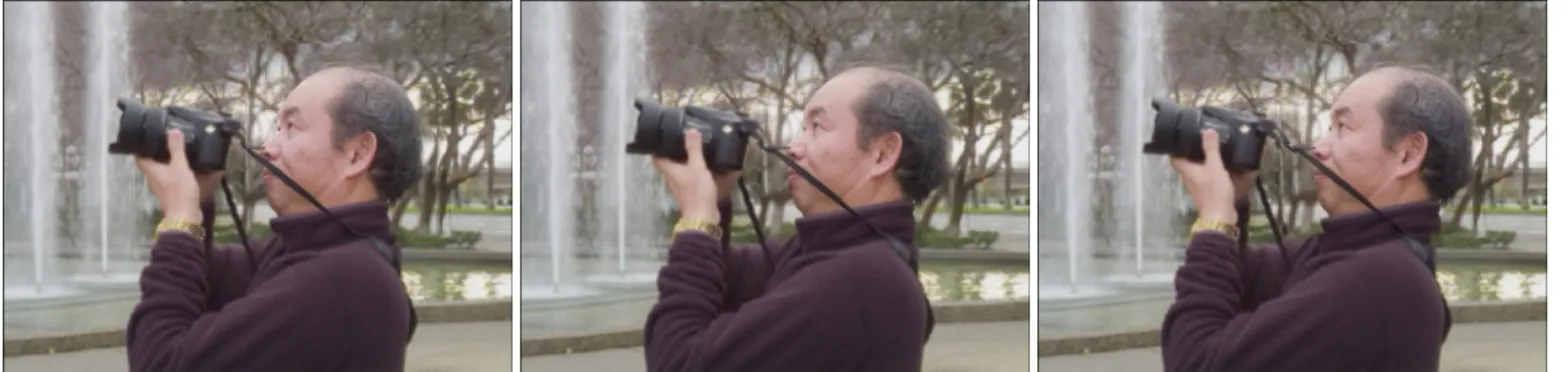
need such a wide FOV. This can be clearly seen in Fig. 6, where three different perspectives where extracted for the ROI and overlaid on the central perspective of the non-ROI. Since the non-ROI basically corresponds to a far away background, changing slightly the perspective from left to right would not change it visibly anyway. On the foreground object however (i.e., the ROI) having a wide FOV is very important because changing the perspective from left to right can change it significantly.
In scenes where there are objects whose depth gradually changes from foreground to the background, such as the railing where the seagull is standing in Fig. 7, there are still some blending inconsistencies to solve. The problem appears when the rendered perspectives of the ROI and the non-ROI are not the same. In Fig. 7, the central view of the base layer (i.e., the non-ROI) was rendered, whereas for the ROI a perspective from the right was rendered.
V. FINAL REMARKS
This paper has proposed a flexible and efficient scalable coding framework for emerging LF applications that provides FOV scalability with ROI support. The proposed FOVS-LFC solution with ROI support comprises an HEVC backward compatible base layer and a flexible number of enhancement layers. The proposed scalable coding architecture satisfies many of the current requirements for the emerging image and video technologies, being easily adaptable to various user case scenarios demanding richer and immersive visualization. Experimental results have shown that the proposed FOVS-LFC solution with ROI support can lead to significant bit savings with unnoticeable differences in rendered views as long as there
is a clear separation in depth between the object included in the ROI and those in the non-ROI. When this is not the case, there are visible blending issues that still need to be solved and will be considered in the future work. A promising solution is to consider an arbitrarily shaped ROI instead of a rectangular one; in this case, a shape coding algorithm will also be needed.
REFERENCES
[1] M. Levoy and P. Hanrahan, “Light Field Rendering,” in Proceedings of
the 23rd annual conference on Computer graphics and interactive
techniques - SIGGRAPH ’96, New Orleans, LA, US, 1996, pp. 31–42.
[2] R. Ng, “Digital Light Field Photography,” Ph.D Thesis, Stanford University, Stanford, CA, US, 2006.
[3] J. Arai, “Integral Three-Dimensional Television (FTV Seminar),” ISO/IEC JTC1/SC29/WG11 M34199, Sapporo, Japan, Jul. 2014. [4] “Lytro Inc.,” 2012. [Online]. Available: https://www.lytro.com/.
[Accessed: 07-Jan-2018].
[5] R. Raghavendra, K. B. Raja, and C. Busch, “Presentation Attack Detection for Face Recognition Using Light Field Camera,” IEEE Trans.
Image Process., vol. 24, no. 3, pp. 1060–75, Mar. 2015.
[6] X. Xiao, B. Javidi, M. Martinez-Corral, and A. Stern, “Advances in Three-Dimensional Integral Imaging: Sensing, Display, and Applications [Invited],” Appl. Opt., vol. 52, no. 4, pp. 546–560, Feb. 2013.
[7] “JPEG Pleno Call for Proposals on Light Field Coding,” ISO/IEC JTC 1/ SC29/WG1 N74014, Geneva, Switzerland, Jan. 2017.
[8] K. Wegner and G. Lafruit, Eds., “Call for Immersive Visual Test Material,” ISO/IEC JTC1/SC29/WG11 N16766, Hobart, Australia, Apr. 2017.
[9] C. Conti, L. D. Soares, and P. Nunes, “HEVC-Based 3D Holoscopic Video Coding using Self-Similarity Compensated Prediction,” Signal
Process. Image Commun., vol. 42, pp. 59–78, Mar. 2016.
[10] Y. Li, R. Olsson, and M. Sjostrom, “Compression of unfocused plenoptic images using a displacement intra prediction,” in 2016 IEEE
International Conference on Multimedia & Expo Workshops (ICMEW),
2016, pp. 1–4.
[11] C. Conti, P. Nunes, and L. Ducla Soares, “Light Field Image Coding with Jointly Estimated Self-Similarity Bi-Prediction,” Signal Process. Image
Commun., vol. 60, pp. 144–159, 2018.
[12] D. Liu, L. Wang, L. Li, Zhiwei Xiong, Feng Wu, and Wenjun Zeng, “Pseudo-Sequence-Based Light Field Image Compression,” in 2016
IEEE International Conference on Multimedia & Expo Workshops
(ICMEW), Seattle, WA, US, 2016, pp. 1–4.
[13] C. Conti, L. Ducla Soares, and P. Nunes, “Light Field Coding with Field of View Scalability and Exemplar-Based Inter-Layer Prediction,” IEEE
Trans. Multimed., pp. 1–1, 2018, doi:10.1109/tmm.2018.2825882.
[14] A. Ebrahimi-Moghadam and S. Shirani, “Progressive scalable interactive region-of-interest image coding using vector quantization,” IEEE Trans.
Multimed., vol. 7, no. 4, pp. 680–687, Aug. 2005.
[15] J. Park and B. Jeon, “Rate-Constrained Region of Interest Coding Using Adaptive Quantization in Transform Domain Wyner–Ziv Video Coding,”
IEEE Trans. Broadcast., vol. 62, no. 3, pp. 685–699, Sep. 2016.
[16] T. Georgiev, “Todor Georgiev Gallery of Light Field Data.” [Online]. Available: http://www.tgeorgiev.net/Gallery/. [Accessed: 17-Sep-2016]. Fig. 7 The perspective inside the ROI was obtained from the right, while the
perspective of the non-ROI area is the central one. Since the railing spans various depths in the scene, a clear blending problem can be seen where the ROI and non-ROI join. Please refer to the ROI highlighted in Fig. 5c (left).
Fig. 6 Three examples of changing the perspective inside the ROI (from right to left) and fixing the non-ROI area in the central view. Please refer to the ROI area highlighted in Fig. 5a (left).