Dezembro, 2018
Mário Rui Monteiro Marques
Master of Science in Electrical Engineering
Reference Model for Interoperability of Autonomous
Systems
Dissertação para obtenção do Grau de Doutor em Engenharia Eletrotécnica e de Computadores
Orientador: Fernando Coito, Prof. Associado,
Universidade Nova de Lisboa
Co-orientador: Victor Lobo, Prof. Catedrático, Escola Naval
Júri:
Presidente: Prof. Doutor Jorge Teixeira, FCT-UNL
Arguentes: Prof. Doutor José Victor, IST
Prof. Doutor António Serralheiro, AM
Vogais: Prof. Doutor Jorge Lobo, UC
Prof. Doutor Aníbal Matos, FEUP
Prof. Doutor José Oliveira, FCT-UNL
Reference Model for Interoperability of Autonomous Systems
Copyright © Mário Rui Monteiro Marques, Faculdade de Ciências e Tecnologia, Universidade Nova de Lisboa.
vii
Firstly, I would like to thank my supervisor, Professor Fernando Coito, and co-supervisor, Professor Victor Lobo for their guidance, patience and contribu-tion to the successful complecontribu-tion of this thesis work.
My acknowledgments to the Portuguese Navy for giving me the oppor-tunity to be a PhD student and to FCT for hosting this research.
My appreciation to the Professors and staff of the Naval Academy for their support.
ix
Esta tese propõe um modelo de referência para descrever os componentes de um Sistema Não-Tripulado Aéreo, de Superfície ou Subaquático (UxS) e o uso de um Sistema para Alcançar Interoperabilidade (IBB) para comandar, controlar e obter feedback de tais veículos. A importância e as vantagens de tal modelo de referência, com uma nomenclatura padrão e taxonomia, são mostradas. Analisa-mos os conceitos de interoperabilidade e alguns esforços para alcançar modelos de referência comuns em outras áreas. Em seguida, apresentamos uma visão ge-ral dos sistemas não-tripulados existentes, descrevendo a sua história, caracterís-ticas, classificação e missões. O conceito de Interoperability Building Blocks (IBB) é apresentado para descrever padrões, protocolos, modelos de dados e frameworks, e um grande conjunto deles é analisado. Um novo e poderoso modelo de refe-rência para o UxS, denominado RAMP, é proposto, que descreve os vários com-ponentes que um UxS pode ter. É um modelo hierárquico com quatro níveis, que descreve as componentes do veículo, a ligação de dados e o segmento terrestre. O modelo de referência é validado mostrando como ele pode ser aplicado e pode estruturar a descrição e o modo como os UxS são usados em vários projetos em que o autor trabalhou. Um exemplo é dado sobre como um único padrão foi ca-paz de controlar um conjunto heterogéneo de UAVs, USVs e UGVs.
xi
This thesis proposes a reference model to describe the components of an Un-manned Air, Ground, Surface, or Underwater System (UxS), and the use of a single Interoperability Building Block to command, control, and get feedback from such vehicles. The importance and advantages of such a reference model, with a standard nomenclature and taxonomy, is shown. We overview the concepts of interoperability and some efforts to achieve common refer-ence models in other areas. We then present an overview of existing un-manned systems, their history, characteristics, classification, and missions. The concept of Interoperability Building Blocks (IBB) is introduced to describe standards, protocols, data models, and frameworks, and a large set of these are analyzed. A new and powerful reference model for UxS, named RAMP, is proposed, that describes the various components that a UxS may have. It is a hierarchical model with four levels, that describes the vehicle components, the datalink, and the ground segment. The reference model is validated by showing how it can be applied in various projects the author worked on. An example is given on how a single standard was capable of controlling a set of heterogeneous UAVs, USVs, and UGVs.
xiii
LIST OF FIGURES ... XVII
LIST OF TABLES ... XXI
ACRONYMS ... XXIII
1. INTRODUCTION ... 1
MOTIVATION ... 1
RESEARCH QUESTION ... 3
RESEARCH METHOD ... 5
CONTRIBUTIONS OF THE THESIS ... 6
THESIS STRUCTURE ... 8
2. BACKGROUND ... 9
RELEVANT CONCEPTS ... 9
EXAMPLES OF ORGANIZATIONS AND PROCESSES INVOLVED IN INTEROPERABILITY ISSUES ... 12
OSI ... 13
ITIL ... 15
OODA Loop ... 16
RELEVANT MILESTONES FOR UNMANNED SYSTEMS ... 17
Unmanned Aerial Vehicles (UAV) ... 17
Unmanned Surface Vehicles (USVs) ... 25
Unmanned Ground Vehicles (UGVs) ... 30
Unmanned Underwater Vehicles (UUVs) ... 35
CLASSIFICATION OF UNMANNED SYSTEMS... 40
xiv
Unmanned Surface Vehicles (USVs) ... 45
Unmanned Ground Vehicles (UGVs) ... 47
Unmanned Underwater Vehicles (UUVs) ... 50
Unmanned Hybrid Vehicles (UHVs) ... 51
MISSIONS ... 52
Military Missions ... 52
Civilian Missions ... 56
3. INTEROPERABILITY BUILDING BLOCKS (IBB) ... 59
MOST RELEVANT INTEROPERABILITY BUILDING BLOCKS ... 59
Standardization Agreement (STANAG) 4586: Standard Interfaces of UAV control systems (UCS) for NATO UAV interoperability... 59
Joint Architecture for Unmanned Systems (JAUS) ... 64
Mission Oriented Operating Suit (MOOS) ... 68
Compact Control Language (CompactCL) ... 70
Common Control Language (CommonCL) ... 72
Coupled Layered Architecture for Robotic Autonomy (CLARAty) ... 75
European Component Oriented Architecture (ECOA) ... 77
Battle Management Language (BML) ... 79
Autonomous Vehicle Command Language (AVCL) ... 82
Multi-sensor Aerospace-ground Joint Intelligence surveillance and reconnaissance Interoperability Coalition (MAJIIC) ... 84
NATO Industrial Advisory Group (NIAG) Subgroup 157 (Study on Multi-Domain Unmanned Vehicle Control) (NIAG - 157) ... 86
Robot Operating System (ROS) ... 89
Lightweight Communications and Marshaling (LCM) ... 94
Micro Aerial Vehicle Communication protocol (MAVlink) ... 95
Inter-Module Communication (IMC) ... 97
COMPARISONS ... 99
Summary of advantages and disadvantages of the IBBs reviewed. ... 99
Comparison of the main characteristics of the IBBs reviewed ... 102
Comparison of Standards ... 104
Comparison of Data Models ... 105
Comparison of Frameworks ... 106
xv
4. RAMP – OUR PROPOSED REFERENCE MODEL ... 109
VEHICLE COMPONENTS (MAIN SYSTEMS -MB1.MSX) ... 111
MB1.MS1 - Platform ... 112
MB1.MS2 - Communications ... 112
MB1.MS3 - Power and Propulsion ... 114
MB1.MS4 - Sensors ... 124
MB1.MS5 – Navigation and Control ... 135
MB1.MS6 - Payload ... 140
DATALINK COMPONENTS (MAIN SYSTEMS -MB2.X) ... 140
GROUNDSEGMENT COMPONENTS (MAIN SYSTEMS -MB3.MSX) ... 142
MB3.MS1 Control Station (GCS) ... 143
MB3.MS2 Communications ... 144
MB3.MS3 Launch and Recovery ... 144
MB3.MS4 Support Equipment ... 148
5. VALIDATION ... 149
VALIDATION OF THE REFERENCE MODEL ... 149
Autoland... 150
Seagull ... 158
GammaEX ... 164
VALIDATION THAT A SINGLE IBB CAN COVER A BROAD RANGE OF VEHICLES (VARIOUS USV,UAV, AND UGV) AND CONVERSION BETWEEN IBBS ... 173
ICARUS and the use of a single IBB for heterogenous vehicles ... 174
STANAG 4586 - MAVLink Gateway. ... 186
6. CONCLUSIONS ... 189
FROM A RESEARCH QUESTION TO VALIDATION OF THE HYPOTHESIS ... 189
INTEGRATION WITH OTHER RESEARCH ACTIVITIES ... 190
Research Projects ... 190
Working Groups ... 192
Member of Organizing Committees ... 197
PUBLICATIONS SUMMARY ... 198
Book Chapters ... 198
Papers published in journals ... 199
Papers presented in conferences ... 199
xvi
Invited Oral Presentations ... 202
FUTURE WORK ... 203
xvii
List of Figures
FIGURE 1-1-RESEARCH METHOD ... 5
FIGURE 2-1 – OSI MODEL ... 14
FIGURE 2-2-ITSERVICE MANAGEMENT LIFECYCLE ... 15
FIGURE 2-3-OODALOOP ... 16
FIGURE 2-4-AIR RAID USING BALLOONS ... 17
FIGURE 2-5 – THE AERIAL TARGET. ... 18
FIGURE 2-6-THE HEWITT-SPERRY AUTOMATIC AIRPLANE. ... 18
FIGURE 2-7FRITZ X. ... 19
FIGURE 2-8-V-1 THE GERMAN FLYING BOMB ... 19
FIGURE 2-9-OPERATION APHRODITE AND PROJECT ANVIL ... 20
FIGURE 2-10-DRONE CONTROL AIRCRAFT CARRYING TWO BQM-34SFIREBEE TARGET DRONES ... 21
FIGURE 2-11-THE QH-50CDASHUAV BEING RECOVERED ABOARD A SHIP ... 21
FIGURE 2-12THE PIONEER UAV ... 22
FIGURE 2-13-THE PREDATOR UAV ... 23
FIGURE 2-14-LAUNCH OF A BOEING SCANEAGLE... 24
FIGURE 2-15-THE AEROVIRONMENT WASP. ... 24
FIGURE 2-16-EVOLUTION OF UAVS ... 25
FIGURE 2-17-THE TESLA "TELEAUTOMATON" ... 26
FIGURE 2-18-GABET AND HIS "TORPILLE RADIO-AUTOMATIQUE" ... 26
FIGURE 2-19-DECONTAMINATION OF NAVY APEX DRONE BOATS ... 27
FIGURE 2-20-THE MITARTEMIS ... 27
FIGURE 2-21-THE AUTOCAT ... 28
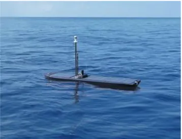
FIGURE 2-22–BARLAVENTO... 28
FIGURE 2-23-WAVE GLIDER USV BY LIQUID ROBOTICS ... 29
xviii
FIGURE 2-25-PROTOTYPE OF THE WICKERSHAM LAND TORPEDO ... 30
FIGURE 2-26 – TELETANK ... 30
FIGURE 2-27 – GOLIATH ... 31
FIGURE 2-28-COMPOSITION OF "SHAKEY" ... 31
FIGURE 2-29-THE STANFORD CART DISPLAYING AUTONOMOUS MOVEMENT ... 32
FIGURE 2-30-THE WHEELBARROW USED AS A BOMB DISPOSAL TOOL ... 32
FIGURE 2-31-THE DARPA'S AUTONOMOUS LAND VEHICLE ... 33
FIGURE 2-32-THE DEMOII VEHICLE AND ENVIRONMENT ... 34
FIGURE 2-33 – IRONCLAD ... 34
FIGURE 2-34-EVOLUTION OF UGVS ... 35
FIGURE 2-35-DEPLOYMENT OF THE SPURVI ... 36
FIGURE 2-36 – ÉPAULARD ... 36
FIGURE 2-37–AUSS ... 37
FIGURE 2-38–ABE ... 37
FIGURE 2-39 – ODYSSEY ... 38
FIGURE 2-40 – THESEUS ... 38
FIGURE 2-41-THE WHOI’S REMUS ... 38
FIGURE 2-42-HUGIN 3000... 39
FIGURE 2-43-EVOLUTION OF UUVS ... 40
FIGURE 2-44-UNMANNED SYSTEMS DIVIDED INTO CATEGORIES... 41
FIGURE 2-45-OURANOS ... 43
FIGURE 2-46-UX-SPYRO QUADCOPTER ... 43
FIGURE 2-47-SKELDARV-200MARITIME ... 44
FIGURE 2-48-THE NORTHUP GRUMMAN GLOBAL HAWK ... 44
FIGURE 2-49-THE NORTHRUP GRUMMAN FIRE SCOUT (MQ-8B) ... 45
FIGURE 2-50–AUTONOMOUS SAILINGFAST ... 46
FIGURE 2-51-ROAZII ... 46
FIGURE 2-52-CALZONI U-RANGER ... 47
FIGURE 2-53 – ICARUS LIGHT UGV ... 48
FIGURE 2-54-IRONCLAD. ... 49
FIGURE 2-55 – GUARDIUM ... 49
FIGURE 2-56–SEACON. ... 50
FIGURE 2-57-REMUS600 ... 51
FIGURE 2-58 – THESEUS ... 51
FIGURE 2-59-MILITARY MISSIONS ... 53
FIGURE 2-60-CIVILIAN MISSIONS ... 56
FIGURE 3-1-ELEMENTS OF THE UAVSYSTEM IN STANAG4586 ... 60
xix
FIGURE 3-3-AN EXAMPLE OF A STANAG4586 MESSAGE. ... 63
FIGURE 3-4-JAUS ARCHITECTURE ... 65
FIGURE 3-5-THE JAUSDOCUMENTS THAT CONSTITUTE THE STANDARD ... 66
FIGURE 3-6-MOOSFUNCTIONAL STANDARD ... 69
FIGURE 3-7-CONNECTION BETWEEN NODES OF A COMPACTCLSYSTEM ... 72
FIGURE 3-8-COMMONCLLAYERS ... 74
FIGURE 3-9-CLARATY LAYERS ... 76
FIGURE 3-10-BMLCONNECTION ... 80
FIGURE 3-11-MAJIICDATA EXCHANGE ... 85
FIGURE 3-12-NIAG157LAYERS ... 87
FIGURE 3-13-BASIC ROS FUNCTIONAL SYSTEM ... 91
FIGURE 3-14-IMCMESSAGE FLOW ... 98
FIGURE 4-1-HIERARCHICAL TAXONOMY ... 110
FIGURE 4-2-RAMPMAIN BLOCKS ... 111
FIGURE 4-3-EXAMPLE OF A MB1.MS1 – PLATFORM FOR A UGV ... 112
FIGURE 4-4-CONCEPTUAL VIEW OF AN UXS POWER AND PROPULSION SYSTEM ... 114
FIGURE 4-5-ENERGY SOURCE CLASSES... 116
FIGURE 4-6-EXAMPLE OF A MB1.MS3.SS1.2 –BATTERY SW1870. ... 116
FIGURE 4-7-EXAMPLE OF A MB1.MS3.SS1.4 –SOLAR POWER VEHICLE. ... 117
FIGURE 4-8-ENERGY TRANSFORMERS CLASSIFICATION. ... 118
FIGURE 4-9-EXAMPLE OF A MB1.MS3.SS2.1 –PHOTOVOLTAIC SYSTEMS. ... 119
FIGURE 4-10-TYPES OF POWERPLANTS. ... 120
FIGURE 4-11-EXAMPLE OF A MB1.MS3.SS3.5–ELECTRIC MOTOR AMPFLOW. ... 122
FIGURE 4-12-MECHANICAL COUPLING CLASSIFICATION. ... 122
FIGURE 4-13-TYPES OF PROPULSION EFFECTOR. ... 123
FIGURE 4-14-MAIN CONTROL EFFECTORS. ... 124
FIGURE 4-15-SENSORS ... 126
FIGURE 4-16-EXAMPLE OF A MB1.MS4.SS1 –CAMERA NATIONAL INSTRUMENTS NI1722. ... 127
FIGURE 4-17-EXAMPLE OF A MB1.MS4.SS2 –GPSEAGLE TREE. ... 127
FIGURE 4-18–EXAMPLE OF A MB1.MS4.SS8–BAROMETRIC ALTIMETER 1ADMD. ... 129
FIGURE 4-19-EXAMPLE OF A MB1.MS4.SS14 –ANEMOMETER WINDMATE WM-200. ... 133
FIGURE 4-20–EXAMPLE OF A MB1.MS4.SS16–A TEMPERATURE SENSOR OMEGA, THAT USES A THERMOCOUPLE. ... 134
FIGURE 4-21-EXAMPLE OF A MB3.MS1 –CONTROL STATION ... 143
FIGURE 4-22-EXAMPLE OF A MB3.MS3 –NET RECOVERY SYSTEM ... 146
FIGURE 5-1-AUTOLAND SYSTEM ARCHITECTURE ... 150
FIGURE 5-2-COMMUNICATIONS COVERAGE ... 153
xx
FIGURE 5-4-BEACONS CAPTURE TEST ... 155
FIGURE 5-5-NET RETENTION TEST ... 156
FIGURE 5-6-UAV ADAPTATIONS ... 157
FIGURE 5-7-FINAL LANDING TESTS ... 158
FIGURE 5-8-SEAGULL SYSTEM ARCHITECTURE ... 159
FIGURE 5-9-IMPLEMENTATION OF THE COMPONENTS ... 162
FIGURE 5-10-LABORATORY EXPERIMENTS ... 163
FIGURE 5-11-EXPERIMENTS AND FLIGHT TESTS... 163
FIGURE 5-12-GAMMAEX SYSTEM ARCHITECTURE... 164
FIGURE 5-13-BATTERIES ... 165
FIGURE 5-14-BRUSHLESS DC MOTOR ... 166
FIGURE 5-15-CAMERA ... 166
FIGURE 5-16-CHEMICAL SENSOR MODULE ... 167
FIGURE 5-17-THERMO SCIENTIFIC RADEYE SPRDRADIOLOGIC SENSOR ... 168
FIGURE 5-18-GROUND STATION WITH WATERPROOF CASE ... 169
FIGURE 5-19-EMERGENCY MANAGEMENT SYSTEM VITALIZATION TOOLS OF THE GCS ... 169
FIGURE 5-20-GROUND STATION COMMUNICATION EQUIPMENT ... 170
FIGURE 5-21 -CASE WITH ACCESSORIES ... 170
FIGURE 5-22-EXAMPLES OF ICARUSLEVELS OF INTEROPERABILITY ... 176
FIGURE 5-23-ICARUSJAUS TOPOLOGY ... 177
FIGURE 5-24-EXAMPLE OF IMPLEMENTATION USING JAUS BRIDGES ... 178
FIGURE 5-25-ICARUSSERVICES ... 178
FIGURE 5-26-R2C BOX ... 179
FIGURE 5-27-ICARUSUAVS ... 179
FIGURE 5-28-ICARUSUGVS ... 180
FIGURE 5-29-ICARUSUSVS ... 181
FIGURE 5-30–ICARUS RESULTS OF THE VALIDATION IN SEA SCENARIO ... 184
FIGURE 5-31 – ICARUS RESULTS OF THE LAND DEMONSTRATIONS ... 186
xxi
List of Tables
TABLE 2-1-CHRONOLOGICAL EVOLUTION OF UNMANNED SYSTEMS. ... 40
TABLE 2-2-CLASSIFICATION OF UAVS,USVS,UGVS,UUVS. ... 42
TABLE 3-1-ADVANTAGE AND DISADVANTAGES OF SOME IBBS ... 100
TABLE 3-2-CHARACTERISTICS OF THE IBBS REVIEWED ... 102
TABLE 3-3-STANDARDS COMPARISON ... 104
TABLE 3-4-DATA MODELS CHARACTERISTICS ... 105
TABLE 3-5-FRAMEWORK COMPARISON ... 106
xxiii
Acronyms
A
ABE - Autonomous Benthic Explorer
ACM - Association for Computing Machinery ADCP - Acoustic Doppler Current Profiler
ADS – B - Automatic Dependent Surveillance–Broadcast AHRS - Attitude and Heading Reference System
AIS - Automatic Identification System ALV - Autonomous Land Vehicle
ASC - Application Software Component
ASCAMM - Associació Catalana d'Empreses constructores de Motlles i Ma-trius
ASI - Air Speed Indicator
ASISTS - Aircraft Ship Integrated Secure and Traverse System ASW - Anti-Submarine Warfare
ATEX – Atmosphere Explosive
AT/FP - Anti-Terrorism / Force Protection AV – Air Vehicle
xxiv AUSS - Advanced Unmanned Search System AUV – Autonomous Underwater Vehicle
B
BEAR - Battlefield Extraction Assist Robot BLOS - Beyond Line Of Sight
BML - Battle Management Language BSD - Berkeley Software Distribution
C
C2 - Command and Control
C2IS - Command and Control Information Systems
C4I - Command, Control, Communication, Computer and Intelligence CAE - Computer Aided Engineering
CBRN - Chemical, Biological, Radiological and Nuclear CCI - Command and Control Interface
CCITT – Comité Consultatif International Téléphonique et Télégraphique CCISM - Command and Control Interface Specific Module
CCU - Command and Control Unit CDT - Control Data Terminal
CINAMIL - Portuguese Army Research Center CINAV - Portuguese Navy Research Center
CLARAty - Coupled Layered Architecture for Robotic Autonomy CMRE - Centre for Maritime Research and Experimentation CN3 - Communication/Navigation Network Codes
xxv CommonCL – Common Compact Language CompactCL – Compact Control Language CONOPS – Concept of Operations
CRC - Cyclic Redundancy Check CS - Control Station
CSD - Coalition Shared Database CSO - Collaboration Support Office CSW - CRITICAL Software
CUCS – Core UAV Control System
D
DARPA - Defense Advanced Research Projects Agency DCCL - Dynamic Compact Control Language
DDS - Data Distribution Service
DIN - Deutsches Institut für Normung DLI – Data Link Interface
DM – Domain Model
DoD – Department of Defense DVL - Doppler Velocity Log
E
ECOA - European Component Oriented Architecture EO – Electro Optics
EOD - Explosive Ordnance Disposal EPnP - Efficient Perspective n Point
xxvi ET - Exploratory Teams
ETC2 – Estação Terrestre Comando e Controlo ETP – Estação Terrestre Payload
ETHZ - Eidgenoessische Technische Hochschüle Zürich EW - Electronic Warfare
F
FEUP - Faculdade de Engenharia da Universidade do Porto
G
GCS - Ground Control Station
GIS - Geographic Information System
GMDSS - Global Maritime Distress and Safety System GMTI - Ground Moving Target Indicator
GPL - General Public License GPS – Global Positioning System
GSM - Global System for Mobile Communications GUI - Graphical User Interface
H
xxvii
I
IA - Influence Activities
IBB - Interoperability Building Blocks IBM - International Business Machines
ICARUS - Integrated Components for Assisted Rescue and Unmanned Search Operations
ID - Inspection/Identification
IEEE – Institute of Electrical and Electronics Engineers IMC - Inter-Module Communication
IMU - Inertial Measurement Unit
INESC - TEC - Institute for Systems and Computer Engineering, Technol-ogy and Science
INS - Inertial Navigation System IoC – Inversion of Control
IR- Infra Red
ISO – International Organization for Standardization ISR – Intelligence, Surveillance and Reconnaissance ITIL – Information Technology Infrastructure Library ITSM - IT Service Management
ITU - International Telecommunication Union
J
JAUGS - Joint Architecture for Unmanned Ground Systems JAUS - Joint Architecture for Unmanned Ground Systems
JC3IEDM - Joint Consultation, Command and Control Information Ex-change Data Model
xxviii JSD - JAUS Service Definition
JSIDL - JAUS Service Interface Definition Language
L
LAN - Local Area Network
LARS - Launch and Recovery System
LAUV - Light Autonomous Underwater Vehicle LBL - Long Base Line
LCGLE - Land Capability Group for Land Engagement LCM - Lightweight Communications and Marshaling LDM - Logical Data Model
LGPL - Lesser General Public License
LHLRS - Light Harpoon Landing Restraint System LIDAR - Light Imaging Detection and Ranging LOI - Levels of Interoperability
LORAN - Long Range Navigation LOS - Line Of Sight
LS - Lecture Series LUGV - Large UGV
LVDT - Linear and Rotary Variable Differential Transformer
M
MAC - Medium Access Control
MAJIIC - Multi-sensor Aerospace-ground Joint Intelligence surveillance and reconnaissance Interoperability Coalition
xxix
MAVlink - Micro Air Vehicle communication protocol MB - Main Blocks
MCI - Multilateral Interoperability Programme Common Interface MCM - Mine Countermeasures
MDARS - Mobile Detection Assessment and Response System MDCS - Multi-Domain Control Station
MDPU - Medium access control Protocol Data Units MFW - Multi-Function Workstation
MIP - Multilateral Interoperability Programme MIT – Massachusetts Institute of Technology MIO - Maritime Interdiction Operations MS - Main Systems
MSG - Message
MOOS - Mission Oriented Operating Suit MOOSApp - MOOS Applications
MOOSDB – MOOS Database
MOU - Memorandum of Understanding MPCS - Mission Planning and Control System
N
NAAG - NATO Army Armaments Group
NASA – National Aeronautics and Space Administration NATO - North Atlantic Treaty Organization
NCOIC - Network Centric Operations Industry Consortium NIAG - NATO Industrial Advisory Group
xxx NPS - Naval Postgraduate School
O
OGC - Open Geospatial Consortium OMG - Object Management Group OODA - Observe, Orient, Decide and Act OSI - Open System Interconnection
OSRF - Open Source Robotics Foundation
OSOCC - On-Site Operations and Coordination Center OUSD - Office of the Under-Secretary of Defence
P
PPO - Payload Operator workstations
POSIX – Portable Operating System Interface PSM - Platform Specific Model
PWM - Pulse Width Modulation
Q
QoS – Quality of Service
QREN - Quadro de Referência Estratégica Nacional
R
R2C - Robot Command and Control RA – Reference Architecture
RADAR - Radio Detection and Ranging
xxxi RC - Radio-Control
REX - Robotic Exercises RF - Radio Frequency
ROS – Robot Operative System
RPAS - Remotely Piloted Aircraft System RS - Recommended Standard
RTG - Research Task Groups RVT - Remote Video Terminal
S
SAE - Society of Automotive Engineers
SAIL - Stanford Artificial Intelligence Laboratory
May referred to: SAR - Synthetic Aperture RADAR SAR – Search and Rescue
SATCOM - Satellite Communications SAS - Synthetic Aperture SONAR
SCI - Systems, Concepts, and Integration panel SEC2 – Sistema Embebido de Comando e Controlo SEP – Sistema Embebido de Payload
SIGINT - Signals Intelligence
SISO - Simulation Interoperability Standards Organization SLAM - Simultaneous Localization and Mapping
SM - Specialist Meeting
SNA - Systems Network Architecture
xxxii SS - Sub-Systems
STANAG - Standardization Agreement SOA - Service Oriented Architecture SOF - Special Operations Forces
SONAR - Sound Navigation and Ranging
SUNNY - smart unattended airborne sensor network for detection of ves-sels used for cross border crime and irregular entry
SUGV - Small UGV SY - Symposia
T
TACAN - Tactical Air Navigation
TCP/IP - Transmission Control Protocol / Internet Protocol TCS - Time Critical Strike
TIC - Thermal Imaging Camera TLV – Type – Length – Value TRL - Technology Readiness Level
U
UAM - Utility Acoustic Modem UAV - Unmanned Aerial Vehicle UCAP - Unmanned Rescue Capsule UCS - UAV Control System
UDP - User Data Protocol
xxxiii UK - United Kingdom
U.S. - United States
USAR - Urban Search and Rescue USB - Universal Serial Bus
USB IF - Universal Serial Bus Implementers Forum USV - Unmanned Surface Vehicle
UUV - Unmanned Underwater Vehicle
UWWCG - Under Water Warfare Capability Group UxS - Unmanned System
V
VDT - Vehicle Data Terminal VHF - Very High Frequency VSI - Vertical Speed Indicator VSM – Vehicle Specific Module
W
WAN - Wide Area Network
WHOI - Woods Hole Oceanographic Institution
X
XDR - eXtensible Markup Language Data Reduced XML – eXtensible Markup Language
1
1.
Introduction
The aim of this chapter is to present the motivation for this work, the re-search question and the hypotheses generated by this question, the rere-search method used, the contributions of this thesis and the structure that this thesis follows.
Motivation
Unmanned Systems (UxS) are changing the way military and civil opera-tions are carried out. One of the reasons why development in this area is of great importance is that robotic systems do not require the logistical footprint that a human being requires to operate[1]. Such systems do not eat (but still need power) which reduces the logistic burden considerably. They do not rest or sleep (but need maintenance) and so will be operational 24 hours a day, reducing the
need for multiple shifts. They don’t suffer as much as humans from cold or heat
(but their components have limits) and that’s why they have fewer
environmen-tal restrictions. They don’t have the training requirements of human beings, and the introduction of software upgrades can be easily implemented, which reduces the preparation time for each type of mission.
Each unmanned vehicle (UxV) is created with one main goal in mind and will have space and means to support sensors and equipments required to ac-accomplish the mission[2]. With the increasing popularity of this kind of system,
it’s expected that there will also be an increase in demand, as well as further
de-velopment. With the increasing demand, more people will want to thrive in this
2
industry which in turn enables the development of more technology. Logistics, software, sensors and communication are just some of the areas that will be
im-proved, and it’s expected that their price will be lower, and their capabilities will be enhanced, both in the military and civilian applications[3].
Today each company develops its systems with their own structure, their own commands, and their own control station. In the end, this company may have a system that can operate very efficiently by itself, but in combined opera-tions it will be difficult if not impossible to operate in conjunction with other ve-hicles. If each system was developed using a common reference model, interop-erability would be much simpler.
The benefits of common reference model are obvious, but the main ones are:
Interaction and cooperation between UxS will be easier to accom-plish;
A single ground station will be able to control more than one system,
avoiding the “forest of computers” that is common when multiple
vehicles are used[4];
Software will be reusable between different systems, reducing costs and reducing the time necessary to develop the systems;
Training (both for operation and for maintenance) will be easier be-cause of common components;
Prices can be lower because of scale economies (the same compo-nents are used in many different systems);
Prices can be lower because there will be more manufacturers, and thus competition amongst them;
The logistical chain will be simplified because there will be less dif-ferent components;
Finding a component can be easier because it will be used in many different systems and from different vendors;
3
The learning curve for new competitors, universities, and even hob-byists will be smoother, thus fostering more development and inno-vation.
Standardization is thus essential in the development of robotic and automa-tion systems. Lacking guidance and standardizaautoma-tion in robotics may cause slower development, or lead to divergence of development, causing frustration not only for consumers but also manufacturers. Standardization not only facili-tates commercialization and knowledge transfer, but also guides research and development activities towards more focused solutions[5].
If researchers and developers where more familiar with existing standards, data models, frameworks and protocols it would be easier to adopt them from the outset, thus simplifying later efforts to promote cooperation. This could lead to a qualitative change in the way we use UxS, by enabling the implementation of new concepts of operation for multi-UxS scenarios, and greater integrations of these systems[6].
Although many reference models have been proposed, most of these have a partial or specialized view of the general area of UxS, and none of them has a clear dominance of the market.
A single, all-encompassing and easy to use a reference model would be a great step ahead for robotics. However, this may be an illusion: one may ask if it
is at all possible, and if it is, why hasn’t it appeared yet? This is the motivation for developing this thesis.
Throughout history, the military community has frequently been the driv-ing force of technology and is at the root innovations that go from satellite navi-gation and airplanes to steam engines, optimization theory, and quality control. In fact, the defense of a nation requires these innovations and the military are the ones with money for that achievements. As a military, this is a big motivation to work in this area.
Research Question
4
these systems, making them aware of each other, executing tasks that require co-operation (both by design and by self-organization), and finally implementing flock or swarm behaviors[7]. Although many standards have been proposed, most of these systems have their own command and reporting protocols, and consequently require their own ground control stations. This profusion of proto-cols makes it very difficult to implement cooperation between systems. Their op-eration and maintenance, in multiple vehicle environments, also poses an unnec-essary burden due to lack of unified standards. A common solution is to develop wrappers and gateways from one system to another. This solution is generally sub-optimal in characteristics, and computationally inefficient.
A better solution would be to have either a single system of protocols de-signed from the start to work with each other, sharing a common view of what a UxS is and how it is organized. This is however an unrealistic expectation at this moment, given the development already achieved in many systems, and would
probably suffer the same fate as other “all encompassing” approaches that have
been attempted in technology, such as the Multics project of Bell Labs[8] in the 60s or the enforcement of Ada by the Department of Defense (DoD)[9] in the 80s.
In fact, there may be no such “single system of protocols” that addresses all
prob-lems raised by UxS.
Therefore, the main research question chosen for this work is the follow-ing:
Is there a reference model that describes all components and issues concern-ing unmanned vehicles that are relevant to achieve interoperability of heter-ogenous groups of such vehicles, and a standard that following that reference model achieves that interoperability?
To answer the main research question of this thesis, the hypothesis pro-posed are:
H 1 -It is possible to achieve interoperability amongst heterogeneous un-manned vehicles if they all share a common reference model (which we pro-pose) and use one of the existing communication methods to exchange mes-sages.
5
Research Method
The research method used is based on the classical approach proposed by [10], and is composed of several steps[11]. The method is represented in Figure 1-1 and then explained in the following paragraphs.
Figure 1-1 - Research Method
The first step is to formulate the research question. This sets the goal for all the thesis and all subsequent work should help to find an answer to this question.
Research background is the second step of the proposed research method. It is an essential step, as it implies extensive research about the subject and any other related work in the area. The scope of this research should be very broad, as it makes the next steps of the method easier.
Based on the information gathered on the step above, the third step is to
6
As was mentioned before, the fourth step is to design the experiment and ex-ecute it. This is the first practical step of the research, and it is often implies de-signing a prototype, a system architecture, or other solutions or experiments.
The fifth step is to test the hypothesis, collecting data. In our case, it is im-portant to evaluate the reference model proposed and to conduct tests, simulat-ing in different scenarios which should be very close to reality, where we can assess the validity and applicability of the model.
After the realization of tests, the results should be interpreted and analyzed to validate the proposed solution. However, if the results are not satisfactory, it is possible to return to step 3, and formulate new hypothesis.
In order to validate the work done, it is important to publish results. The results should be presented to the scientific community to be shared and inter-preted. This presentation is done through scientific papers, presented in scientific conferences or in journals.
Contributions of the thesis
The “holy grail” concerning interoperability issues would be finding a
framework with protocols and tools that would encompass all possible needs and uses of autonomous vehicles. Reality is much harsher, because no single framework encompasses all these needs, and many different frameworks exist. Comparing these different frameworks, protocols, software tools, etc. is by itself a very challenging task, because there is no commonly adopted reference model where the different blocks can be “categorized” or “placed”. Since this is a rela-tively new area in science and engineering, each community has developed its own conceptual model (even if not always explicitly shown), and comparisons are very difficult.
7
model defined different levels of communication and sorted the various prob-lems to be solved in each layer. Although the protocols developed in direct ac-cordance to this model had only moderate success (few people use X.25 or X.400
nowadays), it was extremely important to “organize the heads” of students,
de-velopers, and users, and led to an explosion of network solutions. Each person could say which problems or layers were addressed by their developments. We hope to provide a similar reference model to unite and make comparable the ar-senal of tools, middleware, protocols, etc., that exist for autonomous vehicles.
With a bit of “tongue in cheek” we named it The RAMP (from Reference Ad-vanced Model from Portugal), since we hope it will be a ramp for a rapid and sustained development in this area.
Another example can be taken from computer science and the software in-dustry, where frameworks such as the Portable Operating System Interface (POSIX) or computer graphics frameworks (as described e.g. in [12]) allowed a rapid de-velopment of their respective areas. Even the models used in single products, such as UNIX, shaped the view that an entire community has on a problem, and almost all modern operating systems can and are compared to UNIX.
Certain basic principles apply to all interoperability efforts. For example:
Robustness to new developments. Interoperability should not curtail the development of new features. There should be a path that allows new features to appear without disrupting the existing systems. For example, many communication protocols provide this robustness by adhering to the Type-Length-Value (TLV) principle: when a new fea-ture (type) is added, legacy systems can detect that the type is new, but will know how many bytes are used by this new feature
(Length), and can “jump” over the extra information (Value);
8
Independence from specific technologies and uses. Since technology develops rapidly, the interfaces must be independent of it and out-live a specific technology. Likewise, interoperability efforts that had one specific use in mind many times end up having a much broader application in new fields.
Thesis Structure
This thesis is organized in six major chapters. The first chapter presents the motivation that led to the choice of this topic; the research question and hypoth-esis; the method chosen to develop this research; the contributions of this thesis and its structure.
The second chapter introduces some concepts required to understand the thesis; overviews the history of unmanned vehicles; classifies unmanned vehicles in different categories; and presents some of the missions usually (or potentially) given to unmanned vehicles.
In chapter 3, we overview the most relevant interoperability building blocks used in unmanned vehicles and present some comparisons between them.
The fourth chapter explains the reference model we propose, that is appli-cable to all types UxVs.
Chapter 5 validates the reference model presented in chapter four by giving examples of UxV, used in research projects where we were involved, where the reference model fits perfectly. We also provide an example of a research project, using a fleet of heterogeneous UxV where not only the reference model fits, but where we actually used a common interoperability building block that allowed the desired interoperability.
9
2.
Background
This Chapter explains important concepts used in this dissertation, pro-vides a review of different types of unmanned vehicles, and a possible classifica-tion of unmanned vehicles. It also discusses the missions where they can be used.
Relevant Concepts
When it comes to the study of systems, or systems of systems[13], the con-cept of interoperability is paramount for the functioning of a system entity[14]. However, it is important to define some concepts that are fundamental to under-stand this work:
Standard. A standard is a document that defines the characteristics, such as dimensions, safety or performance aspects, of a product, pro-cess or service[15]. A standard usually defines a set of rules and mod-els that a system should have, or formats that they use. The imple-mentation of standards can be facilitated by the use of common
frameworks or functional structures between systems;
Framework. According to the Information Technology Standards and Or-ganizations Glossary,[16] a framework is “a real or conceptual struc-ture intended to serve as a support or guide for the building of
some-thing that expands the structure into somesome-thing useful”. Usually, a
framework has different layers of standards, and software that facil-itates the use of those standards;
10
Architecture can be defined as a conceptual model that describes the structure, organization, behaviours and components that compose the overall system[15];
Model. The concept of model can be introduced at a system level, as being a representation of a certain object[17];
Data model is an abstract way of defining how data is represented in system, aiming to conceptualize and structure the way information is represented and stored[18];
Middleware. This is a concept that is used to refer to software that connects two different complex programs;
Structure is the general arrangement, organization and disposition of the materials that make an object or a system that is more complex. When used in construction it is the arrangement of the fundamental elements of a building that allow it to stand. When used in UxS it is
the arrangement of the components or “the skeleton” of the
vehi-cle[15];
Format may be the shape, size, general makeup, general plan of or-ganization or arrangement of something. When referring to comput-ers, it can also be a method of organizing data and how the infor-mation is encoded and stored;
Service is the providing of activities or any other needs that are nec-essary for someone or something. In computer science a service might be a background activity, proving a function to other pro-grams, that is required for the system to work[18];
Message. In the context of UxS, a message is a block of information or data, organized according to a code, language, or predefined format, transmitted by an emitter to a receiver[19];
11
Protocol, is defined as a set of regulations that determine how the data should be transmitted in the network, usually specifying sets of mes-sages to be used in the communication[15];
Communication method. A communication method is a system that al-lows the exchange of information, or at least data, amongst system. In this thesis communication methods are mainly used to allow in-teractions between unmanned vehicles and their control stations, but communication methods are also used within the vehicles, within the ground control stations, and with external systems. In this con-text, communication methods can involve standards, data models, frameworks, and protocols;
Interoperability. According to the Institute of Electrical and Electron-ics Engineers (IEEE)[15], interoperability is defined as the capability of a system to work with another without great limitations or addi-tional effort from the user, which can only be achieved using stand-ards. This is one conceptual view of interoperability, but interopera-bility is a broad concept which extends itself to a vast number of dif-ferent areas. In health care, interoperability is known as “the ability of health information systems to work together within and across or-ganizational boundaries to advance the effective delivery of
healthcare”[20]. In telecommunications, it can be defined as the ca-pability of providing and accepting services from different systems, enabling these services to work effectively together[21]. Within the North Atlantic Treaty Organization (NATO), it is defined as the
abil-ity of two or more nation’s forces to train, exercise and execute effec-tively assigned missions and tasks[22]. When it comes to software, interoperability is the ability to communicate, transfer data and exe-cute programs between different units which require little or no knowledge of the characteristics of the units to the user.
12
For the armed forces, interoperability is usually considered at four different levels (strategic, operational, tactical and technological):
At a strategic level, interoperability is important as a coalition builder. It facilitates contributions between countries, for example, between NATO members. At this level, interoperability means shar-ing strategies, doctrines and definitions of force structures in such a way that the other nations understand them and can interact with them. The cost of not having interoperability at this level leads do a fallout amongst the coalition and problems at a political level;
At operational and tactical levels interoperability requires that dif-ferent forces share planning methodologies (and the plans them-selves) and that training of different units is done using similar ap-proaches, so that the forces interact seamlessly, know how their part-ners will react, and trust each other. Lack of interoperability at this level will result in not being able to deploy forces from different na-tions at the same time in the same scenario, thus missing out in pos-sible synergies of different forces;
At the technological level interoperability focuses on systems and terfaces. At this level, different systems must be able to exchange in-formation and interact with other systems to achieve the desired ef-fects. The rapid development of technology and its complexity has made interoperability at a technological level a major concern for NATO, that has a vast set of technical standards, named Standardi-zation Agreements (STANAG), and recommends all nations to ad-here to them so as to allow nations to work together and reduce costs [22].
Examples of organizations and processes involved in interoperability issues
13
of issues, to worldwide organizations involving governments or industry lead-ers. All play an important role and interoperability standards, models, or frame-works need their support to flourish. Some organization, such as International Organization for Standardization (ISO) or Deutsches Institut für Normung (DIN), are maintained by governments (or the United Nations themselves) and have as their sole purpose the regulation of standards. Others, such as IEEE or Association for Computing Machinery (ACM) are professional associations that saw the need to provide standards, guidelines, or recommendations within their professional areas. Organizations such as the Open Geospatial Consortium (OGC), Network Centric Operations Industry Consortium (NCOIC), Web Ser-vices Interoperability Organization, Universal Serial Bus Implementers Forum (USB IF), Bluetooth, etc, are associations of commercial companies, universities, or other stakeholders that formed those organizations to pursue common inter-ests in very specific areas[23]. Specially important for the area of UxS we have NATO with its STANAGS, that address issues such as command and control protocols, ground control station layouts, data formats for images and video, etc.
We shall now overview some interoperability efforts that have had an im-portant impact in their sectors.
OSI
In the beginning of the 80’s computers were starting to be connected to each
other, and various research projects (such as the DARPA ArpaNet projects) and companies (such as International Business Machines (IBM) with its Systems Net-work Architecture (SNA), or Xerox with Xerox NetNet-work System (XNS)) were starting to develop different networking systems. These systems were not in-teroperable, and in many cases, they were propriety systems with copywrite and patent protection. Networking was difficult to achieve, and difficult to address because there was no underlying model that all could agree on. Thus, even com-paring the different systems was a difficult task.
14
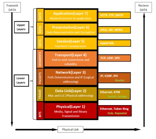
the OSI Model. This model defined 7 layers (Figure 2-1), specifying what prob-lems should be addressed at each layer, and how these layers interacted. CCITT
went on to define the “X” standards, that covered the different layers of the
model. The model was thus “populated” with different standards. For example,
X25 (that actually predates OSI) defines a packet switching system for level 3 and X400 a mail processing system that covers aspects from level 5 to level 7. More importantly, networking systems that were quite different from the 7-level model, such as Transmission Control Protocol / Internet Protocol (TCP/IP) that had developed out of ArpaNet, were mapped to the OSI level, and their features could easily be compared thanks to that mapping.
Figure 2-1 – OSI model
15
(e.g. comments on OSI vs TCP/IP in [24]), they did provide the common ground for all protocols.
ITIL
The Information Technology Infrastructure Library (ITIL) is an important set of rules that should be considered for the operation and management of tech-nological systems. It was developed and introduced in 1990, and consists of a set of documents and libraries with the objective of promoting the management of information and technological systems, in order to deliver to the client, the best product possible[25]. This library enables organizations to use common practices to identify, plan, deliver, improve and support IT services. As an example, it de-fines the IT Service Management (ITSM), as is represented in Figure 2-2. In this cycle, five phases are used: strategy, design, transition, operation and improve-ment.
Figure 2-2 - IT Service Management Lifecycle
16
OODA Loop
Although not formally a standard, but in practice a useful and wide-spread
conceptual framework, especially in the UxS community, we have the “OODA Loop”. This stands for Observe, Orient, Decide and Act (OODA), and is a cycle of steps for a decision process. This process can be seen in Figure 2-3. It was devel-oped by United States Air Force Colonel John Boyd (e.g.[26]). This loop was orig-inally developed for strategy in military operations and combat scenarios, but it can be adapted to suit almost any decision process. Nowadays, this model is dominant in Command and Control (C2).
Figure 2-3 - OODA Loop
As can be seen in Figure 2-3, the ODDA cycle is a loop, where observe is the
act of gathering information about the environment. In the case of UxS’s, this can be the acquisition of targets or images. The next phase is orient. This refers to pointing the system to a certain function. This phase filters the observed infor-mation, through the experience, culture, ability to analyse and synthetize. This can be applied to UxS when filtering the information that was gathered, so as to only keep what is important. The decide activity is where the decision process is actually done. This is done based on the information that was gathered and fil-tered. Decision leads to the final phase, act. Act stage is doing the task that was decided previously. After this, another observation is done, and the loop contin-ues (e.g.[27]).
17
Relevant Milestones for Unmanned Systems
Unmanned systems have been used throughout most of recorded history, but we are interested only in those that have significant autonomy. In the follow-ing sections we shall review some of the important landmarks in their develop-ment. We shall start with the air vehicles, since these have had the greatest im-pact, and will then go on to maritime (surface), ground vehicles and underwater.
Unmanned Aerial Vehicles (UAV)
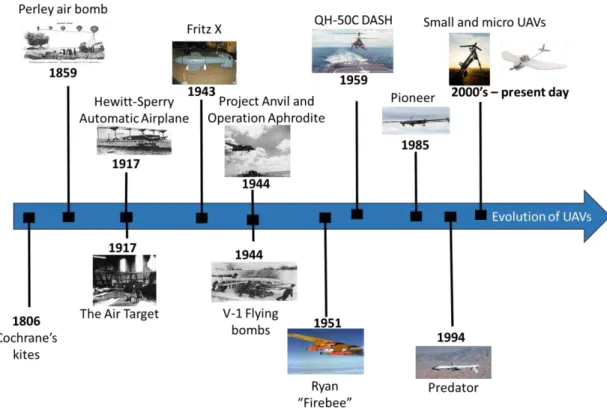
Nowadays, UAVs are becoming common equipment. It's a technology that has been evolving from the military to the civilian world. The precursors of this technology date back to the nineteenth century, with the use of kites and balloons to spread information and to deliver air strikes. One of the first uses of UAVs was in 1806, when an officer from the British Navy, Thomas Cochrane launched kites using a frigate's guns to deploy leaflets over France[28]. Fifty-three years later, Austrians deployed balloons (Figure 2-4), armed with bombs, over Venice. A few years later, balloons used as unmanned aerial bombers started to be patented by Charles Perley.
Figure 2-4 -Air raid using balloons
Source: [29]
In World War I, several attempts were made to use unmanned airplanes.
18
Figure 2-5 – The Aerial Target.
Source: [31]
In following year, Elmer Sperry and Peter Hewitt (that had been working
on the concept of an “aerial torpedo” for some time) built the “Hewitt-Sperry
Automatic Airplane” (The Flying Bomb) (Figure 2-6), which managed to fly 80 Km with 136 Kg bomb, with the aid of a launching platform.
Figure 2-6 - The Hewitt-Sperry Automatic Airplane.
Source: [32]
This success led to the construction of rail-launched Kettering Aerial
Tor-pedo “Bug”, for the U.S. Army, by the Dayton-Wright Airplane Company, in 1918[33]. In the European front, Germany also developed a similar project, “The
19
During World War II, in 1943, the German remote guided missile “Fritz X” (Figure 2-7), successfully sank an Italian vessel proving that Germany was reach-ing new technological ground with the advancements on the remote-controlled vehicles/missiles.
Figure 2-7 Fritz X.
Source: [34]
These developments led to creation of the “V-1 Flying bombs” (1944) ( Fig-ure 2-8) or the Vergeltungswaffen, a jet airplane first used in 1944 against Britain, resulting in great casualties[35]. Contrary to the Fritz X and other pre-existing UAVs, the V-1 was not remotely controlled by radio, but was indeed autono-mous, in the sense that after its launch it had no control link.
Figure 2-8 - V-1 the German Flying Bomb
20
The United States (U.S.) also contributed for the development of the UAVs technology by responding to German menace with their experiments, namely in operation APHRODITE and Project Anvil, in 1944 (Figure 2-9). This consisted in a two-man crew that operated the BQ-7 aircraft until a certain range of its target. When inside that range, the pilots would abandon the aircraft leaving it to be remotely controlled from a B-17. World War II marked a substantial evolution of the development of the unmanned technology. Despite some shortcomings the technology was promising, which resulted in further development during the Cold War years[37].
Figure 2-9 - Operation APHRODITE and Project Anvil
Source: [38]
During the Cold War, unmanned systems were used to perform missions of reconnaissance and surveillance. This was possible because of the progress of
propulsion and guidance sub systems. The beginning of the 1950’s (1951) was
marked by the creation of the jet-propelled subsonic Ryan “Firebee” UAV (Figure 2-10). These UAVs were originally used for target practice, but later on modified
21
Figure 2-10 - Drone control aircraft carrying two BQM-34S Firebee target drones
Source: [39]
By the end of the decade, the U.S. Navy had developed the DASH (QH-50) (1959) (Figure 2-11), an unmanned helicopter used for anti-submarine warfare. Remotely controlled from a ship, manned aircraft, or ground vehicle, this UAV carried homing torpedoes and depth charges, and was also capable of deploying sonobuoys and flares[33],[37]. However, the high rate of accidents with the DASH and their poor reliability stopped it from being used operationally throughout the fleet.
Figure 2-11 - The QH-50C DASH UAV being recovered aboard a ship
Source: [40]
22
payloads and taking photographs from various altitudes were used for these pur-poses. In 1965 the first UAV with stealth characteristics, the “Compass Arrow”, producing a low heat and RADAR signature, was created by Ryan Aeronautical (now Northrop Grumman). The end of the Vietnam War and the focus on new cruise missile systems and long-range bombers affected the development of UAVs, effectively stalling it, until the next ensuing conflict[33].
The creation of the “Pioneer” (Figure 2-12), by the Israeli Aircraft Industries, established a new standard for UAVs. Israel had used a previous version of the airplane during the conflict in Beqaa Valley in 1982, and a lot of experience was gained on the operation of UAVs. This got the attention of the U.S. DoD, and the Pioneer started being developed in 1986 for the U.S. forces. It was a small propel-ler aircraft that became famous for being used by the U.S. during the First Persian Gulf War. It was used to deliver air-raids with effective results and without
risk-ing human lives. The “Pioneer” has been commonly employed in operations in Bosnia, Haiti and Somalia, as well as in the War on Terror[33],[37].
Figure 2-12 The Pioneer UAV
Source: [41]
23
discrimination and terrain imaging. These features were used for Intelligence, Surveillance and Reconnaissance (ISR) missions. After further development, this UAV can now carry out more offensive missions due to the capability of carrying a laser designator and missiles. The Predator set the stage for the development
of the ISR capable “Global Hawk”, “Hunter” and “Shadow”, UAVs with an
ex-tended autonomy and capable of carrying a heavier and more technological ad-vanced payload[37],[33].
Figure 2-13 - The Predator UAV
Source: [42]
Recently, small and micro UAVs have been developed, for both civilian and
24
Figure 2-14 - Launch of a Boeing ScanEagle
Source: [43]
An even smaller class of UAV (micro-UAV), like the “Wasp” (Figure 2-15), has emerged recently. These handheld and hand launched systems have shown versatility, proving to be valuable in different types of warfare, ISR missions, search and rescue, agriculture, law enforcement, meteorological services[37],[33].
Figure 2-15 - The AeroVironment Wasp.
Courtesy AeroVironment, Inc.
25
Figure 2-16 - Evolution of UAVs
Unmanned Surface Vehicles (USVs)
Historically, the most well-known Unmanned Surface Vehicles are proba-bly the fireboats used by the British against the Invincible Armada in 1588[44]. This was at the time a common practice, used by many countries. These fireships were rigged by a crew that then abandoned ship and left it to run with the wind. Some later version had in effect mechanical auto-pilots that could, to a certain extent, keep a course even if there were slight changes with the wind.
26
Figure 2-17 - The Tesla "Teleautomaton"
Source: [45]
Remotely controlled surface vehicles became very useful once they were used as weapons. In 1909, Gustave Gabet ran tests (in the Seine, Paris) on his
Torpille Radio-Automatique (Figure 2-18), a steerable floating remotely controlled torpedo[46].
Figure 2-18 - Gabet and his "Torpille Radio-Automatique"
Source: [29]
27
Figure 2-19 - Decontamination of Navy Apex Drone Boats
Source: [47]
During the Vietnam War, USVs were used as remote minesweepers, for ex-ample at Nha Be[48]. This later led to very successful minesweeping systems such as the European Tripartite System[49] .
The Massachusetts Institute of Technology (MIT) Sea Grant college pro-gram of 1993 generated a substantial leap forward in the development of USVs. The first prototype was ARTEMIS (Figure 2-20), a USV designed to test autono-mous navigation and control systems, and later used to collect bathymetry data [50].
Figure 2-20 - The MIT ARTEMIS
28
The ARTEMIS project gave birth to the Autonomous Coastal Exploration System (ACES), followed by the “Autocat” (2000) (Figure 2-21). These USVs were equipped with hydrographic survey sensors that resulted in the improvement of the quality of the surveys[50].
Figure 2-21 - The Autocat
Source: [50].
With the turn of the century, there was a boost in the appearance of USVs
powered by “renewable energy”. These vehicles can harvest energy from the en-vironment, either using wind, solar radiation, or wave energy. One of these USVs is Barlavento (Figure 2-22) developed at The Portuguese Naval Academy[52], that uses rigid sails to capture wind energy[52].
Figure 2-22 – Barlavento
Photographed during the “Robotic Sailing Regatta” of the WRSC, September 2016, Viana do Castelo
29
vehicle, it also has solar panels on top, so as to produce the electricity it needs for on-board electronics. The Portuguese navy first tested one such system in 2013
during the REP exercise (originally “Rapid Environmental Picture”, and now “Recognized Environmental Picture”) and since then they have been regularly used in this exercise.
Figure 2-23 - Wave Glider USV by Liquid Robotics
Image courtesy Liquid Robotics, a Boeing Company
Figure 2-24 summarizes the evolution of USVs, since their inception
30
Unmanned Ground Vehicles (UGVs)
The Wickersham Land Torpedo (Figure 2-25) was probably the first UGV. Created by Elmer E. Wikersham, it was patented in 1928, and was built to deliver explosives to the target. Although it only remained a prototype, it set the pace to future creations[45].
Figure 2-25 - Prototype of the Wickersham Land Torpedo
Source: [45]
In the 1930s, the Russians developed the first UGV used in conflicts, the
“Teletank” (1930) (Figure 2-26), that was a full-sized tank.
Figure 2-26 – Teletank
Source: [53]
31
controlled small tank that was used to reach the enemy and to be remotely ex-ploded, serving as a portable bomb during World War II[54].
Figure 2-27 – Goliath
Source: [53]
One of the greatest innovations of UGV technology occurred with the
crea-tion of “Shakey” (Figure 2-28) in the research department of Stanford University by the Defense Advanced Research Projects Agency (DARPA), in 1969. This was a wheeled mobile robot that used a video camera, a radio link to the controlling computer, a laser range finder and a blocks-world image-reading algorithm to perceive its surroundings[55],[56].
Figure 2-28 - Composition of "Shakey"
32
Along with Shakey, in 1971 the “Stanford Cart” (Figure 2-29) was devel-oped, showing progress by being capable of performing autonomous outdoor movement at a steadier pace. It could follow an unbroken line on a road for about 15 meters independently. These developments marked the beginning of the im-plementation of autonomous navigation systems based on artificial vison[55].
Figure 2-29 - The Stanford Cart displaying autonomous movement
Source: [57]
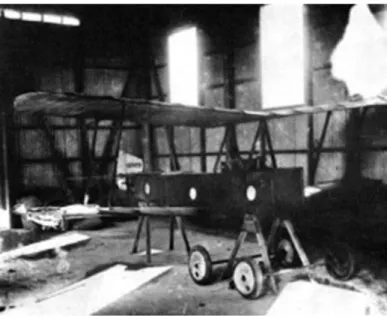
As for remotely controlled vehicles, progress was also made by the
devel-opment of the “Wheelbarrow” (1972) (Figure 2-30), by the British Army. The first Explosive Ordinance Disposal UGV, used in Northern Ireland in response to cas-ualties caused by the Irish Republican Army[54],[58].
Figure 2-30 - The Wheelbarrow used as a bomb disposal tool
33
Along the 1980’s, DARPA developed the “Autonomous Land Vehicle”
(1986) (ALV) (Figure 2-31), that was capable of autonomous on-road and off-road driving and was a self-contained system. It was an eight-wheel vehicle with an inertial land navigation system, ultrasonic sensors, a doppler RADAR, color video camera and a custom laser scanner used for perception. By the end of the decade, it performed off-road programed routes, being capable of obstacle avoid-ance [55].
Figure 2-31 - The DARPA's Autonomous Land Vehicle
Source: [59]
With the beginning of the 1990’s, in 1992, DARPA initiated the DEMO II
34
Figure 2-32 - The DEMO II vehicle and environment
Source: [55]
The current century has resulted in great improvements in UGVs, such as the Mobile Detection Assessment and Response System (MDARS). It uses arrays of sensors to detect obstacles and detect intruders. Another example is the Iron-clad (Figure 2-33), whose purpose is to rescue injured soldiers during conflict.
Figure 2-33 – Ironclad
Courtesy and copyright of BAE Systems
35
Figure 2-34 summarizes the evolution of UGVs, since their inception
Figure 2-34 - Evolution of UGVs
Unmanned Underwater Vehicles (UUVs)
In 1957, what was probably the first UUV was conceived by Stan Murphy, Bob Francois and Terry Ewart, in the Applied Physics Laboratory of the Univer-sity of Washington. This UUV was initially intended to collect oceanographic data in certain regions and under ice. This project triggered the development of
36
Figure 2-35 - Deployment of the SPURV I
Source: [63]
In 1980, the IFREMER’s Épaulard (Figure 2-36) was operational, being the first UUV to support deep ocean photography and bathymetric surveys[64].
Figure 2-36 – Épaulard
Source: [65]
37
Figure 2-37 – AUSS
Source: [66]
The 90’s the production of UUV prototypes increased with the creation of
Autonomous Benthic Explorer (ABE) (1991) by the Woods Hole Oceanographic Institution (WHOI) (Figure 2-38), the “Odyssey” (1992) vehicles by the MIT Sea Grant AUV lab (Figure 2-39), the International Submarines Engineering’s
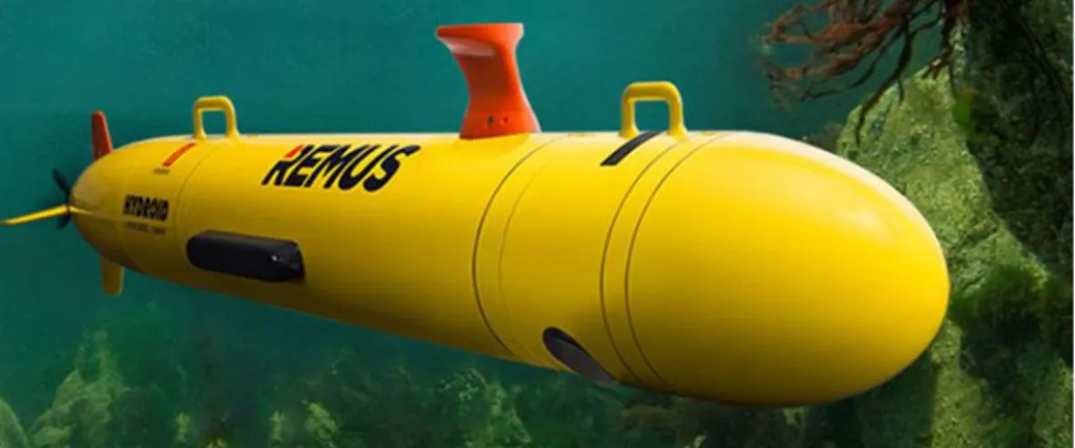
“The-seus” (1995) (Figure 2-40), the WHOI’s “REMUS” (Figure 2-41) and the
South-ampton Oceanography Center’s Autosub.
Figure 2-38 – ABE
38
Figure 2-39 – Odyssey
Source: [68]
Figure 2-40 – Theseus
Courtesy International Submarine Engineering Ltd.
Figure 2-41 - The WHOI’s REMUS
39
These UUVs performed mainly scientific missions with the intent of oper-ating under ice, performing near bottom surveys in rough terrain, laying fiber optic cables under water and ice and ocean monitoring[69],[70],[71],[72].
With the new century, UUVs began to be commercialized to the public. The first enterprise to do so was C&C Technologies of Lafayette, by selling Hugin 3000 UUV (Figure 2-42), for charter. This is a rather large system, used mainly by the oil industry and other large corporations. For less demanding uses, smaller UUV have been developed, with the capability of carrying various types of pay-loads, and equipped with cameras which allow recording of video and still im-ages[73]. Several Portuguese companies have been involved in this area, such as OceanScan with their LAUV (Light Autonomous Underwater Vehicle) and IN-ESC-TEC with its Mares and Tri-Mares system.
Figure 2-42 - Hugin 3000
Photographed during a research project meeting in which CINAV participated in October 2017.
40
Figure 2-43 - Evolution of UUVs
Table 2-1 represents the evolution of unmanned vehicles:
Table 2-1 - Chronological evolution of unmanned systems.
Classification of Unmanned Systems
41
thesis we chose to use the names currently in use with most NATO bodies, that focus on the common fact that all these vehicles are unmanned in the sense that they do not have a human aboard to control (at least in part) the vehicle. In certain fora the names used focus on other aspects. In most European organizations the term Remotely Piloted Aircraft System (RPAS) is used to stress that there is al-ways someone responsible (a Pilot), even though he may be physically outside the plane. In popular parlance, the term Drone is frequently used, but this term usually implies that the system is not intelligent and is simply a slave (and thus it gained a bad name in most military organizations). Other communities, such as the traditional underwater vehicle community, prefer to use terms such as
“Autonomous Underwater Vehicle” (AUV) to stress that the systems must make choices by themselves during the mission. However, there have been objections to the liberal use of the term autonomy, since it is usually pre-programmed in some way (see the discussions on remote control/remote supervision/consented autonomy/full autonomy). To avoid all these pitfalls, we choose to always use
the term “Unmanned”.
These vehicles are usually classified according to where they operate: in the air (UAV), on the surface of water (USV), on the ground (UGV) or under the sur-face of water (UUV) (Figure 2-44).
Figure 2-44 - Unmanned Systems divided into categories
![Figure 2-10 - Drone control aircraft carrying two BQM-34S Firebee target drones Source: [39]](https://thumb-eu.123doks.com/thumbv2/123dok_br/16570063.737970/55.892.259.676.128.391/figure-drone-control-aircraft-carrying-firebee-target-source.webp)
![Figure 2-12 The Pioneer UAV Source: [41]](https://thumb-eu.123doks.com/thumbv2/123dok_br/16570063.737970/56.892.231.621.580.936/figure-pioneer-uav-source.webp)
![Figure 2-19 - Decontamination of Navy Apex Drone Boats Source: [47]](https://thumb-eu.123doks.com/thumbv2/123dok_br/16570063.737970/61.892.277.701.129.401/figure-decontamination-of-navy-apex-drone-boats-source.webp)
![Figure 2-30 - The Wheelbarrow used as a bomb disposal tool Source: [58]](https://thumb-eu.123doks.com/thumbv2/123dok_br/16570063.737970/66.892.265.627.752.1019/figure-wheelbarrow-used-bomb-disposal-tool-source.webp)
![Figure 2-32 - The DEMO II vehicle and environment Source: [55]](https://thumb-eu.123doks.com/thumbv2/123dok_br/16570063.737970/68.892.232.613.129.420/figure-demo-ii-vehicle-environment-source.webp)