Diana Filipa Fernandes Pereira
Filtration efficiency of meltblown webs
Diana Filipa Fernandes Pereira
July 2016 UMinho | 2016 F iltr ation ef ficiency of meltblo wn w ebs
Universidade do Minho
Escola de Engenharia
July 2016
Master Thesis
Polymer Engineering
Trabalho efetuado sob a orientação do
Supervisors:
doc. Ing. Tomáš Sedlácek
Prof. Olga Carneiro
Diana Filipa Fernandes Pereira
Filtration efficiency of meltblown webs
Universidade do Minho
iii
ACKNOWLEGEMENTS
To begin with, I would like thank doc. Ing. Tomáš Sedláček for giving me the opportunity to do my master thesis in CPS (Center of Polymer Systems) from Tomas Bata University, and for his guidance and insight in supervising the research, his help, and kindness.
I also would like to express my gratefulness and appreciation to Ing. Pavel Bažant for his assistance and help in experiments.
This thesis would have not been possible without the 3D filtration modelling, and so I thank Prof. Ing. Martin Zatloukal for use his software providing me the results.
I am grateful to my office colleagues in CPS for receiving me warmly and helping with everything I needed. Special thanks to Chiara for her endless support and friendship every day of these last months. Many thanks to all my friends, expressly to Laura and Dimitris, for their patience, love, encouragement and unique support.
Finally, I want to express my gratitude to the Erasmus+ traineeship programme and my parents for funding my stay in Czech Republic. Para eles e para a minha irmã, não só pelo apoio financeiro, mas sobretudo emocional, um obrigada de coração.
v
ABSTRACT
Nonwoven fabrics are made from fibers and used across a wide range of applications and products. They are high-tech, innovative and versatile products, indispensable for a lot of application nowadays. Filtration is one of the fastest growing segments in the nonwovens industry, and with the necessity of replacing fiberglass for polymer materials keeping the high filtration efficiency of filter media.
The aim of this thesis is to study the effect of different machine settings on filtration efficiency, from polypropylene meltblown webs.
The webs were produced by meltblowing in two different processing (A and B), with two different dies configuration, for each one it was varied air flow, air temperature and distance-to-collector (DCD).
After collecting samples, they were characterized by basis measures (weight and thickness) and SEM pictures. These information was used for 3D modelling software to obtain the results.
Due to problems in processing B, the web samples were obtained with plenty of defects, and it was not possible take clear conclusions about the use of different dies.
Conclusions of this project shows highest filtration efficiency results were achieved with higher air flow, higher air temperature and smaller DCD.
vii
CONTENTS
List of abbreviations ix
Figures index x
Tables index xii
Chapter 1 1
Introduction 1
1.1. Conceptual framework 3
1.2. Motivation 3
1.3. Aims and objectives 3
1.4. Methodology 4 1.5. Outline 5 Chapter 2 7 Literature review 7 2.1. Nonwoven fabrics 9 2.2. Production of nonwovens 10 2.2.1. Fiber production 10 2.2.2. Web formation 11 2.2.3. Web bonding 13 2.2.4. Finishing treatments 13
2.3. Melt spinning web formation 13
2.3.1. Materials 14
2.3.1.1. Properties 14
2.3.1.1.1. Bicomponent fiber classification Erro! Marcador não definido.
2.3.1.2. Raw materials 15
2.3.1.2.1. Polypropylene 15
2.3.2. Production process 15
2.3.3. Operating variables 18
2.3.4. Effect of process variables 19
2.3.5. Structure development 19
2.3.6. Meltblown vs spunbond 20
2.3.6.1. Meltblown 20
2.3.6.1.1. Structure and properties 20
2.3.6.1.2. Applications 21
2.3.6.2. Spunbond 21
2.3.6.2.1. Structure and properties 21
2.3.6.2.2. Applications 21 2.4. Electrospinning 22 2.4.1. Electrospinning parameters 23 2.4.2. Applications 23 2.5. Samples characterization 23 2.6. Filtration theory 24 2.6.1. Filtration mechanisms 24
viii 2.6.2. Filtration Efficiency 27 2.6.3. Filter parameters 28 Chapter 3 29 Experimental procedures 29 3.1. Introduction 31
3.2. Filter sample preparation 31
3.2.1. Material 31
3.2.2. Meltblown apparatus 31
Processing A 34
Processing B 35
3.3. Characterization techniques 37
3.3.1. Density and thickness 37
3.3.2. Scanning electron microscope 38
3.3.3. Differential Scanning Calorimetry 39
3.3.4. Optical microscope 40
3.4. 3D filtration modelling 41
Chapter 4 43
Results and discussion 43
4.1. Fiber diameter and pore size distributions 45
4.2. Filtration efficiency 47
4.3. Crystallinity 48
4.4. Morphology structure 49
4.5. Effect of variable settings 50
Chapter 5 53 Conclusions 53 5.1. Outcomes 55 5.2. Future work 55 Appendix 57 I. PP Data sheet 59 II. Processing A 61 III. Processing B 63
IV. 3D filtration modelling software setting 65
ix
LIST OF ABBREVIATIONS
ASTM American Society for Testing and Materials DCD Die-to-Collector Distance
EDANA European Disposables and Nonwovens Association INDA Association of Non-woven Fabrics Industry
ISO International Organization for Standardization HPI Holes Per Inch
MB Meltblown MFI Melt Flow Index MFR Melt Flow Rate
MWD Molecular Weight Distribution MPPS Most Penetrating Particle Size PA Polyamide
PE Polyethylene
PET Polyethylene terephthalate PP Polypropylene
QF Quality Factor SB Spunbond
SEM Scanning Electron Microscope
x
FIGURES INDEX
Figure 1. i Methodology flow chart 4
Figure 2. i Diagram of nonwovens production process 10 Figure 2. ii Different principles of fiber production 11 Figure 2. iii Drylaid formation processes: a) carding, b) air-laying 11
Figure 2. iv Wetlaid formation process 12
Figure 2. v Melt spinning formation processes: a) meltblowing, b) spunbonding 12 Figure 2. vi Schematic diagram of common bicomponent fiber cross-sections arrangements 14
Figure 2. vii Melt spinning process diagram 16
Figure 2. viii Schematic air flow through the die assembly 17 Figure 2. ix 3D scheme of part of the die and respectively cross section 17 Figure 2. x Main application areas of spunbond products 22
Figure 2. xi Filtration efficiency curve 27
Figure 2. xii SEM picture of top surface of a sample after filtration 28 Figure 3. i Die assembly: a) spinnerets plates system, b) small metal parts to define setback and air gap, c) the die incomplete and d) the final state of the die. 32
Figure 3. ii Meltblown line 32
Figure 3. iii Thermal cleaning machine 33
Figure 3. iv Two states of DCD setting machine a) lower level, b) higher level 34
Figure 3. v Die A plates system configuration 34
Figure 3. vi Piece of a meltblown web 35
Figure 3. vii Die B plates system configuration 36 Figure 3. viii Problems occurring in processing B 37
xi
Figure 3. ix Microscope Phenon Pro 37
Figure 3. x Sample holder 38
Figure 3. xi Equipment for coating samples 38
Figure 3. xii SEM microscope 39
Figure 3. xiii Correction applied in SEM pictures 39
Figure 3. xiv DSC equipment 40
Figure 3. xv Optical microscope 40
Figure 3. xvi Fibers sample holder 41
Figure 3. xvii 3D structure model creation: a) SEM top view of sample fiber layer; b) zoom in from the same picture; c) fiber centreline determination from b; d) top view of one 3D model layer; e) perspective
view of one 3D model layer; f) full 3D model 42
Figure 4. i Fiber diameter distributions for processing A and B 45 Figure 4. ii Pore size distributions for processing A and B 46 Figure 4. iii Filtration efficiency curves for processing A and B 47 Figure 4. iv Microscope picture from fiber cross section 49
xii
TABLES INDEX
Table 2. i Filtration mechanisms 25
Table 3. i Constant parameters in meltblowing production 33
Table 3. ii Processing A samples conditions 35
Table 3. iii Processing B samples conditions 36
Table 4. i Percentage of crystallinity for samples A and B 48 Table 4. ii General results overview from processing A 50 Table 4. iii General results overview from processing B 51
Table A. i Samples conditions in processing A 61
Table A. ii Samples conditions in processing B 63
CHAPTER 1
Chapter 1. Introduction
3
1.1. CONCEPTUAL FRAMEWORK
Fabrics and textiles are used as synonyms in textile assembly trades. However, they are different terms: a fabric is not a material made of interlacing fibers, it is made through weaving, knitting, spreading, crocheting or bonding. [1]
Nonwoven fabrics are made without any warp or weft, one of the oldest and simplest examples of these products is felt. It is produced from matted and compressed fibers with no apparent system of threads. [2]
The nonwovens industry is very profitable and sophisticated, nowadays it is one of most intensive industries in terms of its investments in new technology, research and development.
Nonwoven products are used across a wide range of applications: absorbent hygienic products, cosmetics, medical, packaging, personal care wipes, agriculture, automotive, cable wrapping, civil engineering, construction, fashion, filtration and industrial applications. They can have many different characteristics allowing a high-performance in many different applications. [3]
During this work, air filtration media is the central application area studied.
1.2. MOTIVATION
The issues motivating this research are mainly originating from filtration industry needs. Nowadays, this industry has evolved to a diverse and technically sophisticated business with very specific requirements for each area of use.
One of the most efficient materials used in air filter devices is fiberglass [4]. However, plenty of researches are being developed on the health side effects of fiberglass by government agencies and private companies. Until now, the results did not contribute to a general consensus about possible dangers fiberglass may put to public health, but concerns persist that fiberglass may cause serious problems. [5]
The necessity of replacing glass fiber materials motivate studies and development on filter media made with polymer materials, as is the case of this project.
To find ways to improve the filtration efficiency of polypropylene melt spinning webs was study the effect of some process variables, trying to contribute for developing worthy and profitable alternatives in air filter media.
1.3. AIMS AND OBJECTIVES
With this project it is pretended to get an overview of nonwoven fabrics in general, focusing in meltblowing webs production, and its preparation using a laboratory scale line.
Chapter 1. Introduction
4
The main aim is to study how filtration efficiency can be improved. For that, it was studied the effect of different machine settings (air flow, air temperature and DCD) and also different die configurations from polypropylene meltblown webs.
1.4. METHODOLOGY
In the following flow chart of Figure 1.i is described the methodology applied to do this thesis.
Figure 1. i Methodology flow chart
In the initial phase was done a literature review to get an overview about nonwovens fabrics in general. With that, an extensive literature survey was obtained, in order to understand what nonwovens fabrics are, which the different production methods are and how they work, which materials can be used, how to evaluate fabrics properties and how they are influenced…
After that, the planning phase started. First of all the main problem was defined: filtration efficiency of meltblown webs. Considering that, some concepts and theories were reviewed and some depth research about filtration efficiency was developed. All in all, the design research could be well-marked: production of polypropylene meltblown webs with two different dies configuration, changing only three machine settings (air flow, air temperature and DCD) in the same way.
Before start the planned processes was necessary assembled all the line components for meltblown production and do some trials.
With the samples collecting, they were prepared and characterized with basic measures (like weight and thickness) and SEM pictures. Gathering all the information, it was possible to use the 3D filtration modelling. Afterwards the data was processed and analysed, and it was possible take concrete results about filtration efficiency.
Chapter 1. Introduction
5
1.5. OUTLINE
This first chapter is an introduction to understand the purpose of this project and what was done. The present work incorporates four other chapters, the summary of which will be following described.
Chapter 2 provides general background information on nonwoven fabrics and their production methods. A conceptual framework focusing on melt spinning web formation is also exposed: the different materials used and their main properties, the production process in detail, the operating variables and their effect, and the main differences between meltblown and spunbond methods regarding the structure and properties webs and the application areas. Afterwards, electrospinning method is also described, including the main parameters and applications. Moreover, the different techniques to characterize these fabrics are briefly exposed. And finally, an overview on filtration theory is done, since the study of filtration efficiency is the main point of this work.
Chapter 3 explains the experimental work developed in view of material and processing method used, characterization techniques performed and a brief overview about the 3D filtration modelling used.
Chapter 4 presents the results obtained showing the effect of the different dies and the machine settings, starting with a general characterization (including fiber diameters and pore size distribution).
At last, chapter 5 summarizes the outcomes of the research and its contribution to this topic. It also suggests future studies based on the results obtained.
CHAPTER 2
Chapter 2. Literature Review
9
2.1. NONWOVEN FABRICS
A nonwoven fabric structure has some particularities that differ them from the other textile structures: instead of yarns, it consists of individual fibers or layers of fibers webs; due to fiber orientation distribution and the arrangement of the bonding points in its structure, it is anisotropic both in terms of its structure and properties; usually it is not very uniform in fabric weight and thickness; and it is highly porous and permeable. [6]
The European Disposables and Nonwovens Association (EDANA) defines a nonwoven as ‘a sheet of fibers, continuous filaments, or chopped yarns of any nature or origin, that have been formed into a web by any means, and bonded together by any means, with the exception of weaving or knitting.’. [3]
The structure and properties of a nonwoven fabric are determined by fiber variables (linear density, tenacity, elongation, modulus, cross-section, morphology), fibers arrangement (filament separation, fabric weight uniformity, fiber orientation distribution, thickness), porous structural parameters (fabric porosity, pore size distribution, pore shape) and, finally, the type of bonding elements and bonding interfaces between fibers. [7]
By manipulating material and operation variables it can be produced a diversity of products with specific properties, which can create innovative and cost-effective solutions [3]. Industries of all types find their answers in nonwoven materials, a few of these industries are following: [27]
Apparel: aprons, gloves, imitation fur, interlinings, medical and surgical apparel, military apparel, outerwear, sportswear and swimwear, protective clothing, shoe linings and insoles, sleepwear, underwear;
Automotive and transportation: acoustic/thermal insulation, boats, car mats, covering for seats, seat belts, door lower coverings and reinforcements, filters, instrument panel trim, sunroof, window frames;
Consumer products: baby bibs, coffee and tea bags, coffee filters, cosmetic applicators and removers, envelopes and labels, reusable bags, vacuum cleaner, and laundry bags;
Electronics: battery separators, cable wrap, circuit boards, electrical insulation, fuel cells, heat and sound insulation;
Filtration: air, gas and dust, food, liquid, medical;
Geotextiles and construction: covers and seed strips, drainage and erosion control, insulation, pavement overlays, roadway reinforcements, roofing components, soil stabilizers;
Hygiene: diapers, feminine hygiene, incontinence products;
Medical and healthcare: bandages, surgical drapes, dressings, sterile packaging and overwraps, surgical masks, swabs.
The most important nonwoven fabrics properties can be organized in some main groups, such as mechanical properties, fluid hangling properties, physical properties, chemical properties and related with specific applications (such as filtration efficiency in filtration media applications). [7]
Chapter 2. Literature Review
10
2.2. PRODUCTION OF NONWOVENS
To understand the general nonwovens production process is presented the diagram of Figure 2.i, where the process is divided in three main stages: fiber production, web formation, web bonding, and finishing treatments.
Figure 2. i Diagram of nonwovens production process
In the following topics will be describe in more detail each one of these stages.
2.2.1. Fiber production
This step can be done based in different generic techniques:
Melt spinning: the fiber-forming includes melting a thermoplastic, which is extruded into air or other gas, where it is cooled and solidified;
Dry spinning: it is extruded, in a continuous stream, a solution of the fiber-forming polymer into a heated compartment to evaporate the solvent;
Wet spinning: consist of continuous extrusion of a solution of the fiber-forming polymer into a chemical bath where the solvent is extracted.
In Figure 2.ii are shown three schematic illustrations of the different processes.
Fiber
production
Melt spinning Dry spinning Wet spinningWeb
Formation
Drylaid . Carding . Airlaid Wetlaid Melt spinning . Spunbond . Meltblown Other technologies . Electrospinning . Centrifugally spinningWeb
Bonding
Chemical Mechanical ThermalFinishing
Treatments
Wet finishing . Washing . Chemical impregnation . Dyeing . Coating Dry finishing . Calendering . Embossing . Emerising . MicrocrepingChapter 2. Literature Review
11
Figure 2. ii Different principles of fiber production [28]
2.2.2. Web formation
Web formation involves converting staple fibers or filaments into a web assembly which will origin the final fabric.
It started with the arrangement of fibers in a sheet or web. The conditions at this stage can be dry, wet or molten – drylaid, wetlaid or polymer-laid (also designated melt spinning).
Drylaid fibers are not continuous, but they are long enough to be handled by conventional spinning equipment [4]. There are two main methods of dry laying: carding and air-laying, as shown in Figure 2.iii.
Figure 2. iii Drylaid formation processes: a) carding, b) air-laying [29]
In the first one the fibers are aligned essentially parallel to each other in the direction that the carding machine produces the web. In contrast, the second one disperses the fibers into a fast moving air stream and condenses them, by means of pressure or vacuum, onto a moving screen. [29]
Chapter 2. Literature Review
12
Wetlaid materials are originate from a process similar to papermaking, with the same manufacturing principle: an aqueous suspension is separated from the fibers to form a uniform sheet of material [4]. In Figure 2.iv the web forming process is illustrated. Many wetlaid fabrics are made with natural blended with synthetic fibers or fiberglass. [29]
Figure 2. iv Wetlaid formation process [29]
Polymer-laid, also known as melt spinning products, have their origin in polymer extrusion processes and the filaments are directly collected to form a web, which afford the opportunity to reduce time and costs production [7]. They are produced by two main methods – meltblowing and spunbonding, which are illustrated in Figure 2.v. In both processes the filaments have been extruded from molten polymer resins, drawn with heated and high velocity air, and laid on a moving screen to form a web. The differences between the two will be described in following chapter.
Chapter 2. Literature Review
13
Other technologies besides the ones described before, include some specialised technologies, in which the fiber production, web structure and bonding usually occur in tandem in the same place [3]. Some of these web-forming technologies enable the production of webs containing submicron filaments, such electrospinning (electrostatic spinning) and centrifugal spinning.
2.2.3. Web bonding
After web formation, further necessary step is web bonding which consists in the web consolidation by chemical, heat or mechanical processes. This is a vital step to produce serviceable fabric, once webs in their unbonded form have little strength [6]. The main methods of web bonding may be summarized in next paragraphs.
Chemical bonding (adhesion bonding) methods consist of applying bonding agents to the web in form of liquid dispersions, polymer solutions, powders and particles [6]. The chemical adhesives can be applied by saturating, spraying, printing or foaming techniques [19]. This method also includes latent bonding using solvents which involves solvating fibers surfaces to provide self- or autogenously bonded fibers at the cross-over points.
The term autogenous bonding is used when the web tend to have a tacky surface (the fibers stick to one another) and, thus, it is self-bonded as it is formed. As higher the degree of autogenous bonding, as stiffer will be the fabric. [19]
Mechanical bonding methods involve changing the texture of fabric surfaces by physically reorienting or shaping fibers. The fibers are bonded together by entangling, entwining and displacing fibers relative to each other or by displacing and stitching the fibers or filaments. [6]
Thermal bonding (cohesion bonding) processes involve altering fabric dimensions or physical properties through the thermally fusing part of fibers surface or through the addiction of heat-sensitive powders. [1, 6]
2.2.4. Finishing treatments
In order to obtain some extra properties is possible modifying or adding some product to the web formed. The new achieved properties can have technical functionality, appearance or aesthetics to improve fitness for purpose. This step can be done before or after bonding. [17]
There are plenty of possibilities to apply these finishing treatments in wet or dry conditions. Some examples of each state are given in the diagram of Figure 2.i.
2.3. MELT SPINNING WEB FORMATION
After a brief introduction about nonwovens fabrics, this thesis will focus only in one production method based in melt spinning processes, which may be described in more detail. Besides the only method used was meltblowing, this category includes also information about spunbonding, since the basis process formation is common to both.
Chapter 2. Literature Review
14
2.3.1. Materials
2.3.1.1. Properties
Most of the nonwoven fabrics are made of fibers from manufactured sources. And the fiber properties have a very important role not only during processing but also in final performance. These properties are dependent on the chemical structure of the fibers’ constituent molecules, its surface characteristics, its morphology, its physical dimensions and its additives, in case of being used. [19]
Some of the main material properties that affect the extrusion and spinning processes are described as follows: [7]
Molecular weight is one of the principal requirement for the material in this processing methods. It should be adjust to obtain low enough viscosity of the melt at the extrusion temperatures in order to permit the attenuation of the polymer fluid stream [19]. This property can be assessed by measuring melt flow index (MFI or MFR);
Molecular weight distribution (MWD) affects the melt elasticity and melt strength which influence the draw force necessary applied to the filaments: narrow molecular weight distribution reduces the melt elasticity and melt strength, so the filaments can be drawn without excessive force; Melting point directly affects the melt temperature and, consequently, the energy required; higher
polymer melt temperature originate smaller fiber diameters because the viscosity is lower and it is easier to draw down the filament;
Melt viscosity is depending of molecular weight and melt temperature: the strength properties has their peak with an MFR around 300, and decreased as the MFR increased above that.
2.3.1.1.1.
Co-extrusion
Co-extrusion technology is often used in melt spinning nonwovens production. It consists in the continuous extrusion of one or more than one polymer type arranged in different configurations within the fiber cross-section.
Bicomponent fiber structures for improved economic efficiency, and functionality can be obtain with an appropriate selection of polymer materials, polymer ratio and fiber cross-sectional geometry. [7]
Bicomponent fibers are commonly available as sheath-core, side-by-side and eccentric sheath-core, as presented in Figure 2.vi.
Figure 2. vi Schematic diagram of common bicomponent fiber cross-sections arrangements [34] Common sheath-core combinations are PE/PP, PE/PET and PA/PET.
Chapter 2. Literature Review
15
There are some obvious advantages in the use of bicomponent fibers, since you can get properties of two different materials [34]. For example, in the sheath-core configuration, the core material can either be a recycled polymer or an electrically conductive material. This cross section is also useful for applications where surface properties such as luster and dyeability, and core properties such as strength is needed. [7]
2.3.1.2. Raw materials
Polyolefins1 lead the raw materials used in nonwovens production because they are relatively inexpensive
and can achieve good properties. Besides these materials, there are other resins used, such as polyester, polyamide, nylon, polyurethane and rayons but with lower ease of use. [4, 7]
Meltblown technology just allow the use of low molecular weight polymers (low viscosity) and relatively narrow molecular distribution. In contrast, spunbond processes can use materials with high molecular weight and broad molecular distribution. [7]
2.3.1.2.1.
Polypropylene
Polypropylene is the most commonly material used in polymer-laid nonwovens due to its low density, ease of processing and suitability for end-use. Another advantage relatively to other materials is that it is hydrophobic, the resin granules or pellets do not need drying. [4]
The majority of meltblown fabrics are made from low molecular weight PP (high MFI). The MFI range suitable for spunbond technology is 20 to 60, and for meltblown it is 100 to 2000. The typical melting temperature is 160-170°C, and when is extruded in a bicomponent system, is often combined with PE and PET. [7, 19]
2.3.2. Production process
In melt spinning technology there are many operations taking place simultaneously: filament extrusion, drawing, lay down and bonding, since the bonding device is placed in line with spinning. It is also possible bond the web in a separately step, and this arrangement is useful if more than one type of bonding is applied to the same web. [7]
In general the line consists of an extruder for forming filaments, a metering pump, a die assembly, a filament spinning, drawing and deposition system, a belt for collecting the filaments, a bonding zone; and a winding unit.
On the following diagram in Figure 2.viii, it is visible the basic operation steps and the evolution of the fabric over time. Each stage will be describe in detail in the followings paragraphs.
1 Polyolefins are obtained from the polymerization of simple olefins (monomers composed of carbon and hydrogen atoms) like polypropylene and
Chapter 2. Literature Review
16
Figure 2. vii Melt spinning process diagram I. Polymer melting:
It occurs like a basic extrusion process: starting by feeding polymer granules from a hopper into the extruder barrel, where there is a rotating screw. The polymer is gradually melted along the barrel due to the heat and friction of viscous flow and the mechanical energy generated between the screw and the barrel, which is transformed into thermal energy. The material pass through the three different zones of the extruder – feed zone, transition zone and metering zone – and it is forced through the die. The metering of the melt is possible to achieve by using a metering pump. This device ensure a uniform melt distribution and the required process pressure, providing constant melt delivery to the die assembly. When the molten solution exit from the extruder should pass through a filter pack that removes contaminating particulates. [19] II. Die assembly:
It has three distinct components: polymer-feed distribution, die nosepiece, and air manifolds. [4] It is necessary take especially care with the feed distribution in melt spinning dies because, by contrast with other extrusion processes, there is no any mechanical adjustment after the molten polymer cross the die. Also because of the high temperature range wherein the process is operated: temperature range where thermal breakdown of polymers proceed rapidly. [4] From the feed distribution channel the polymer goes directly to die nosepiece. It is a wild and hollow metal piece with several hundred orifices across the width, and it involves high costs since the need of very tight tolerances and big precision.
When the polymer melt is extruded from the die, the filament strands are attenuated by hot air to form fine fibers. The air manifolds provides the high velocity hot air through the slots on the top and bottom sides of the die nosepiece, as shown in Figure 2.ix.
Chapter 2. Literature Review
17
Figure 2. viii Schematic air flow through the die assembly [32]
Set back and air gap distances are defined choosing different plates with the desired thickness. To get a clear idea, in Figure 2.ix is shown a die illustration and its cross section
Figure 2. ix 3D scheme of part of the die and respectively cross section [36]
The diameters represented correspond to the spinnerets holes size, and they are defined for set of plates, the set change according the spinneret size desired.
III. Filament spinning, drawing, and deposition:
The stage where it takes place the proper integration of the filaments. After leave die assembly, the fibers progresses toward the collector screen drawing in the surrounding air that cools and solidifies the fibers.
Afterwards, the fibers get laid randomly onto the moving belt (collector), forming a self-bonded nonwoven web. Usually, vacuum is applied inside the collector to withdraw the hot air and improve the fiber laying process. [4]
The filaments are laid down randomly because of the turbulence in the air stream. But the directionality of the splayed filament can be controlled in order to achieve some particular characteristics. [4]
Chapter 2. Literature Review
18
The collector speed and the collector distance from the die nosepiece can be varied according the properties desired. [7]
IV. Bonding stage:
The fiber adhesion and fiber entanglement that occurs at lay down, usually produce enough web cohesion for the web be ready to use. However, additional bonding and finishing processes may further be applied to these webs to alter their characteristics. As it was said before, there are three main techniques used on this stage – thermal, chemical and mechanical, which use is depending mostly on the fabric application. The first two can be applied in two variations: area bonding (bond large regions of the web) or point bonding (bond small regions) [4]. Sometimes two or more techniques can be employed to achieve bonding.
Bonding is usually used to increase web strength and abrasion resistance. As the bonding level increases, the web becomes stiffer.
Thermal bonding is the most commonly used technique. The process consists in fusing filaments in the web at their cross-over points via calendars rollers (contact bonding) or an oven (through-air bonding). Besides conventional thermal fusion there are also some techniques based on different fusion temperatures. [7]
Ultrasonic bonding is a bonding process similar to thermal one, the difference subsists in the way of heating the web: in ultrasonic bonding the heating is achieve by converting mechanical energy applied during the process. This method is preferred for webs of heavy basis weight. And sometimes is followed by calendering to reduce the thickness of the fabric, reducing as well its porosity. [9]
V. Winding:
In the last step to convert a fabric in a good, the web is usually rolled up at the end of the production line and processed further. This step can also include some finish treatments, according to the final application.
2.3.3. Operating variables
Some of the variables are related to the machine and can be changed while the equipment is being operated, others are fixed during a process run and can only be changed when the machine is not in operation. All of these affect the final properties of the nonwoven web.
The main operating variables are presented as follows:
Polymer throughput rate (control the final fiber diameter, fiber entanglement, basis weight and the attenuating zone);
Polymer and die temperature (also influence the final fiber diameter and the texture of the filaments);
Die hole size;
Air flow (helps to control de draw down and air drag);
Air temperature (responsible for the cooling of the filament, thus for the development of microstructure; affect the uniformity, fabric appearance and feel);
Chapter 2. Literature Review
19
Air gap (affects the degree of fiber breakage by controlling the air exit pressure);
Air angle (controls the nature of air flow, i.e. as the air angle approaches 90° it results in a high degree of fiber separation or turbulence that leads to random fiber distribution; at an angle of 30°, roped or parallel fibers deposited as loosely coiled bundles of fibers are generated); Die to Collector Distance (DCD) (affects the openness of the fabric, thermal bonding among the
fibers and basis weight);
Take-up speed (controls the final draw down and filament deposition on the collector);
Bonding temperature and pressure (if calendar bonding is used, it influence the tensile properties of the final fabric).
2.3.4. Effect of process variables
In this section will be described the effect of some operating variables listed above.
Increasing polymer-throughput rates, die swell is greater and the fiber diameters bigger. [7]
Studies concluded the die orifice size has very little effect on the final fiber diameter: since the molten polymer issues from the die nose tip directly to the confluence of the air streams, the greatest amount of attenuation occurs at the point of exit and it is dependent in its melting point, viscosity-temperature characteristics, and surface tension [7]. However, indeed when the orifice size increase, the average fiber diameter is higher for the bigger orifice size.
High air pressure yields uniform and shot free fibers but also interferes with the separation of fiber. Higher air flow produce samples with finer fibers, smaller pores and greater entanglement. [37]
Increasing air temperature, draw down takes place under a low spinline stress that leads to reduction in fiber diameter. The crystallinity structure is clearly affected from this variable: lower air temperature should produce webs with lower crystallinity and orientation, because it will have less cooling time, so faster cooling rate. [7] Though, there are different studies showing different effects from this variable.
Steeper air angle origins fibers with higher degree of dispersion and random orientation. Lower air angle produces a greater number of parallel fibers, greater attenuation and less fiber breakage. [19]
Higher die-to-collector distance produce samples with higher average fiber diameters [16]
2.3.5. Structure development
Molecular orientation is achieved by drawing the filament during its production process (since the spinneret to the rolling point).
The degree of crystallinity is a result from the thermal actions during formation and subsequent heat treatments. The cooling rate influences a lot the development of crystalline structures: slow cooling provides time for greater amounts of crystallization to occur; on the contrary, faster rates yield highly amorphous materials. [38]
The strength level is attribute to the orientation of the polymer molecules along the length of the fiber, to the development of the crystalline structure and the fiber nature [19]. Low molecular orientation,
Chapter 2. Literature Review
20
irregular diameter profiles along the length of the fibers, and voids in the fibers will result in a low strength web. Tenacity and Young’s modulus decrease when die temperature, air pressure, and die-to-collector distance increase. [7]
Fabric hand is depending on fabric rigidity and modulus, fibers diameter and bonding: finer filaments, bonding at lower temperatures and lower basis weight origin softener and more flexible fabrics. [7]
2.3.6. Meltblown vs spunbond
The two main differences between meltblown and spunbond processes are associated to air attenuation techniques used, and they are described below.
The first technique is associated to the temperature and volume of the air used to attenuate the filaments. On one hand, the meltblown process uses large amounts of high-temperature air (air temperature is approximately the same or slightly greater than the polymer melt temperature). On the other hand, the spunbond process normally uses a smaller volume of air close to ambient temperature to first quench the fibers and then to attenuate them. [4]
The second one is regarding the location where the filament draw or attenuation force is applied. In meltblown process, the draw or attenuation force is applied at the die tip while the polymer is molten, which is ideal for forming microfibers but does not allow for polymer orientation to build good physical properties. Whereas, in spunbond process, this force is applied at some distance from the die, after the polymer has been cooled and solidified, this fact provides the necessary conditions to orient the fibers and the resultant improved physical properties, but is not appropriate to forming microfibers. [4]
In resume, with meltblown process smaller diameter fibers are produced, whereas spunbond fabrics have bigger diameters but with greater tensile and strength properties. [19]
In face of the variances exposed between both processes, it is understandable the final products will have different structures and properties, henceforth, they will be used in different applications, as explained in the following topics.
2.3.6.1. Meltblown
2.3.6.1.1.
Structure and properties
The molecular orientation in meltblown fibers is really reduced since a meltblown fabric is not attenuated in the solid state at low enough temperatures. Combining this with the low molecular weight of the polymer, results in weak fabrics without good mechanical properties. [19]
However, the fineness of meltblown fabrics give them a high surface-to-mass ratio, and under appropriate consolidation offer porosity, with pore-size distribution shifting toward significantly smaller sizes. [19]
Besides the characteristics above, there are some others which characterize meltblown fabrics, such as: generally high opacity (high cover factor); microfibers provide a high surface area for good insulation and filtration characteristics; fibers have a smooth surface texture and are circular in cross-section; most
Chapter 2. Literature Review
21
meltblown webs are layered or shingled in structure, the number of layers increases with basis weight. [7]
2.3.6.1.2.
Applications
As explained before, meltblown webs products are characterized by fine fibers and large fiber surface area, which results in enhanced filtration efficiency, good barrier properties and good absorption action. In order that, the main interested markets in the production of meltblowing fabrics are in filtration, insulation, and liquid absorption. [7]
In the filtration media, some specific applications can be outlined: room air filter and recirculation, precious metal filtration and recovery, food and beverage filtration, surgical mask, respiratory filtration and healthcare products. [3]
The large surface area of fibers creates significant drag forces on air convection currents passing through the fabric, making these fabrics perfect to be used in insulation applications.
These products are also widely used on applications requiring liquid absorption for instance feminine sanitary napkins, household and industrial wipes, and disposable adult incontinence absorbent products. [3]
For many other applications, meltblown fabrics are inadequate because of its poor mechanical strength and abrasion resistance. To solve it, laminates of spunbond, meltblown, spunbond (SMS) or other combinations are produced using multibeam installations.
2.3.6.2. Spunbond
2.3.6.2.1.
Structure and properties
Most of spunbond fabrics have a random structure and planar-isotropic properties due to the random laying down step during their production. However, it is possible obtain anisotropic properties by controlling the orientation of the filaments.
Compared to other nonwoven structures, spunbond fabrics have high strength-to-weight ratios. Generally the web is white with high opacity, and webs are layered or have a shingled structure. [7]
These materials are also characterized by good fray and crease resistance, high liquid retention capacity (because of the high void content), high in-plane shear resistance and low drape. [7]
2.3.6.2.2.
Applications
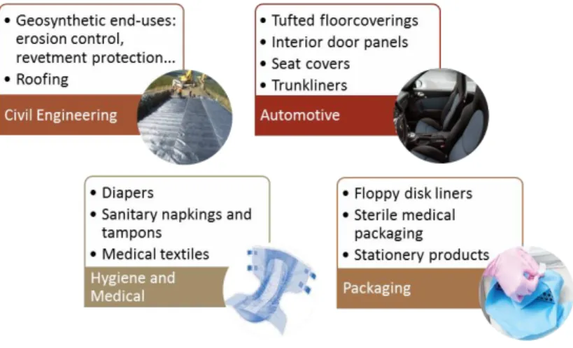
Spunbond nonwoven fabrics can have very different properties extending from very light and flexible structure to a heavy and stiff one. Therefore, there is a big range of applications and they are resumed in the Figure 2.x below.
Chapter 2. Literature Review
22
Figure 2. x Main application areas of spunbond products
The civil engineering area hold over around one quarter percentage of spunbond market. These products have an important paper on this industry due to some important properties such as chemical and physical stability, high strength/cost ratio, and their potential controllable structure. [4]
Other area that had been growing intensely in last years is hygiene and medical. The typical structure of spunbond fabrics helps the skin stay dry and comfortable and properties like breathability, resistance to fluid penetration, lint free structure and sterilizability are important for medical uses.
2.4. ELECTROSPINNING
Other production process studied during this project, for their innovative and recent technology, was electrospinning – electrostatic spinning or electrospinning. In this section this process will be depicted.
Electrospinning is the cheapest and the most straightforward way to produce superfine fibers using electrical forces [12]. This technique to produce nonwoven fabrics has been discussed and investigated in immense detail, because of the potentials of these technique. Besides it allows the production of fibers with nanometre-scale diameters and the use bi-component structures; it is also considered highly efficient because of the set-up and operational cost are relatively low while and the output is very high. [19, 7]
The technique consists in forcing a viscous polymer, composite, gel solution or melt through a spinneret with an electric field to a droplet of the solution, at a metallic needle tip [8]. Under the influence of applied a high voltage, the resulting increase in electrostatic repulsive charge is higher than the surface tension and the droplet is deformed into a conical shape commonly known as a Taylor cone. The solution develops a charge which collects at the free surface of the solution at the tip. During this way, due to drawing and evaporation of the solvent, the jet becomes gradually thin. These effects are accentuated due to the whipping instability of the jet. Then the fibers are elongated and solidifies before being collected, and formed as a nanoscale diameter as a result of these phenomena [19, 20].
If the polymer solution used has low viscosity the jet will break up into small charged particles that are deposited on the collector – electrospray. Conversely, if the solution is relatively viscous the jet will not break up and can be elongated into a very thin fiber. This fiber and the resulting collected web will have varying size and uniformity depending on process parameters used. [7]
Chapter 2. Literature Review
23
2.4.1. Electrospinning parameters
There are several process parameters that control the physical property, geometry and bulk production of electrospun fibers. [7]
The first group of parameters are related with the properties of the material used: [20]
Viscosity: when it is low, occurs beads generations; when it is high, increase in fiber diameter; Polymer concentration: increase of fiber diameter with increase of concentration;
Polymer molecular weight: higher molecular weight will reduce the number of beads and droplets; Conductivity: its increasing, decrease the fiber diameter;
Surface tension: when it is high, results in instability of jets. The other group of variables is the processing parameters: [20]
Applied voltage: higher voltage origin smaller fiber diameters;
Distance between tip and collector: too small and too large distances generate beads, there is a minimum distance required to obtain uniform fibers;
Flow rate: decrease in flow rate will decrease fiber diameters.
Also the ambient parameters can influence and affect fiber morphology: [20] Humidity: high humidity results in circular pores on the fibers;
Temperature: higher temperatures results in smaller fiber diameters.
2.4.2. Applications
As the main application it is highlighted the filtration area. The fine diameter of the fibers origin micropores which help remove very fine particles from air or liquid streams.
Electrospun fibers can also be used in environmental and engineering applications (conducting polymers and composite system), biotechnology (membranes and filters), energy industry (components in solar cells and fuel cells), defence and security (chemical and biological sensors), healthcare (tissue engineering), drug delivery systems and vascular grafts. [19, 12]
2.5. SAMPLES CHARACTERIZATION
For the measurement of nonwoven fabric properties, various testing methods and techniques have been developed by standard authorities (e.g., ISO, ASTM), industrial associations (e.g., EDANA, INDA) and also individual companies or research groups.
In filter media samples characterization there are some important properties to determine, such as basis weight, thickness, fiber diameter and pore size distributions, also thermic and mechanical properties can be measured depending on the focus of the study.
Chapter 2. Literature Review
24
Image analysis (optical microscope) – only usable with lightweight webs since it is based on transmitted light;
SEM analysis;
Transmission electron microscopy (TEM); FTIR (Fourier transform infra-red); Nuclear magnetic resonance (NMR); Wideangle X-ray diffraction (WAXD); Differential scanning calorimeter (DSC);
Dynamic mechanical analyser (DMA) to determine elastic modulus G’ and viscous modulus G’’; TGA;
Dielectrical measurements: Modern broadband dielectric spectroscopy (BDS) is commonly used to analyse materials’ response over a wide frequency and temperature window. BDS is therefore a very powerful tool for examining molecular dynamics and electrical polarizability of polymers over broad temperature and time scales.
2.6. FILTRATION THEORY
The filtration spectrum covers a wide size range of particles – from ionic particles measured in angstroms to larger solids up to several hundred microns in size. Different filtering systems can be used dependent on the requirements. [18]
Contrary to common belief, a filter does not simply capture all particles above a given size. The filter capacity is highly dependent on the particle size as well the air velocity under which the filter is operating. [17]
2.6.1. Filtration mechanisms
Various physical mechanisms act to separate a particle from a fluid stream and retain it on a filter medium. The most predominant capture modes include straining, interception, inertial impaction, Brownian diffusion and electrostatic capture. In the next Table 2.i is described how a single fiber captures a particle according the different filtration mechanism.
Chapter 2. Literature Review
25
Table 2. i Filtration mechanisms [17, 9, 13, 18, 26, 33]
Filtration mechanism Illustration2 Description Particle size
Straining The particle is larger than the space between fibers, so it is captured and does not follow the airstream through.
Larger than pore size of membrane
Interception
A particle approaching the fiber’ surface to a distance equal to or less than its radius, or within the contact range of the fiber, tends to adhere to the fiber and deposit on its surface, without crossing
a flow streamline.
Low micrometer to sub-micrometer
Inertial impaction
Streamlines generally do not change direction until relatively close to the fiber. Due to the inertia associated with a moving particle of large size (at high enough particle velocities), the particle is unable to adjust quickly enough to the changes in streamline directions
and it will continue along its original path, impact the filter fiber and deposited there.
Micrometer range (medium
sized particles)
Chapter 2. Literature Review
26 Table 2. ii Continued
Filtration mechanism Illustration3 Description Particle size
Brownian diffusion
Fine particles in the air stream collide with the gas molecules and create a random path through the media. As these small particles
are bumped by the gas molecules they too begin moving randomly about, bumping into other particles as well. This phenomena is called Brownian motion of gas molecules. And as
its consequence, small particles are deviate from the airstream and come into contact with the filter fiber.
Small sized particles (predominant
with low gas velocities and
smaller particles)
Electrostatic capture
It only happens when is imparting an electrostatic charge to a synthetic fiber during its formation. Due to attraction of the charges, the particles make contact with the fiber and becomes attached. The small particles initially adhere to the fibers and form
the nucleus for progressive attachment of more particles, which finally results in the formation of conglomerate protuberances on the fibers. Continual attachment of the particles onto each other results in the development of dendrite colonies which load the filter, reduce the spacing between adjacent fibers, reduce the size of the voids in the filter and hence enhance the filtration efficiency
of the filter medium.
Nanometer range
Chapter 2. Literature Review
27
2.6.2. Filtration Efficiency
Air filter media defy common sense by actually trapping smaller and larger particles more effectively than mid-sized particles. [17]
When the filtration efficiency is graphed against the particle size an upside down bell curve is generally observed, as it is presented in the Figure 2.xi. This curve (designated by Total in the graph, in blue) is the result of the other two ones (orange and green).
Figure 2. xi Filtration efficiency curve [39]
The various filtration mechanisms acting in removing particles from a gas stream are directly related to the size of the suspended particles. Particles above around 0,3 µm in size can be captured by straining, interception and inertial impaction (whose efficiency curve is in green). While smaller particles can be captured via the aid of Brownian diffusion and electrostatic capture (the respectively efficiency curve is in orange). However, there is a critical particle size which is very difficult to capture, because it is too small by one side and too big by other side, this is shown by the smaller area of the efficiency curve and marked as MPPS (Most Penetrating Particle Size). [17]
The filtration efficiency is also dependant on the time. The curve in the graph will move up as the time pass, since the particles are going to accumulate in the filter sample, decreasing the probability of other particles pass through the fibers, and thus improving the filtration efficiency.
In the Figure 2.xii is shown a SEM picture of an air filter sample after some time of use, where it is perfectly visible the particles agglomerated in the fibers.
Chapter 2. Literature Review
28
Figure 2. xii SEM picture of top surface of a sample after filtration [40]
2.6.3. Filter parameters
The concepts are now expanded upon to determine the parameters that play significant rolls in the filtration efficiency of bulk fiber mats.
Fiber diameter is one of the most important parameters. In order to obtain high efficiency, the pore size and the structural elements of a filter must be approximately the same size as the particles being captured [7]. Decreasing fiber diameter, the number of fibers per unit area increases. Also, the path that the particle must take through the filter media becomes much more complex, thus increasing the chances of capture the particle on the fiber surface.
As thinner the fibers diameter, smaller are the pores size, greater specific surface area of the finer fibers and higher degree of fiber entanglement for the greater number, which result in better filtration efficiency. [37]
The matt thickness – total thickness of all layers of fibers that make up the filtration media, also have an important role. It makes sense, intuitively, to assume that a thicker layer of fibers will result in higher efficiency of the filter. However, once a certain threshold is reached adding further fibers to the matt may not increase efficiency. Because, as the matt thickness is increased the pressure drop across the filter also increases. And pressure drop has a direct relationship to the amount of energy required to cause the air to flow through a filter. In almost all applications, a lower pressure drop is better and is required to keep costs low [15]. Therefore, the added thickness will produce a poor overall performance. [7]
Other indicator to evaluate filters performance is the quality factor (QF), and it can be calculated according the following equation: [8]
𝑄𝐹 = −ln(𝐸)/∆𝑝
where ∆𝑝 is the pressure drop and E is the filtration efficiency for the most penetrating particle size (MPPS).
CHAPTER 3
Chapter 3. Experimental work
31
3.1. INTRODUCTION
Meltblowing was used to produce micro scale samples, all with the same material. This method was chosen due to the appropriate structure and properties to filter media, as explained in the topic 2.3.6.1.. Fibers were spun in two different dies (which are differentiated as Processing A and B), for each one, it was variate three different setting machines.
The weight and thickness of samples was measured. The samples were also characterized by a scanning electron microscope. These data were used by the simulation software 3D modeling of filtration described in [8], to obtain fiber diameter and pore size distributions, and evaluate the filtration efficiency of each sample.
Also DSC tests were performed to evaluate the percentage of crystallinity. And some pictures in the optical microscope to see the fibers cross section.
This chapter will detail the filter sample preparation – material used and description of the production process; the techniques and analysis devices employed in the samples characterization; and, for last, a brief overview of the simulation software used.
3.2. FILTER SAMPLE PREPARATION
3.2.1. Material
The material PP HL708FB is a polypropylene homopolymer intended for fiber applications and recommended for meltblown applications. Especially for its high MFR value: 800g/10min (at 230°C/2,16kg). This polymer supplied by Borealis was used as the MB fiber material. The respective data sheet can be consulted in Appendix I.
3.2.2. Meltblown apparatus
Nanofiber webs were prepared with a polymer melt filament laboratory line, model LBS-300. This is a bicomponent melt extrusion machine designed to run low volume trials and to be easily upgradable by adding options with the initial purchase or future options purchases. Different processes can be simulated in this machine, including FDY (Full Draw Yarn), spunbond, meltblown and monofilament.
All of the above processes use the same extrusion system, where polymer pellets are placed in hoppers feeding each extruder. The extruder barrels are corrosion resistant in order to allow processing of fluoropolymers. [21]. On the end of the extruder screw there is a mixing element (Maddox), to insure a homogeneous supply of polymer to the pump.
The polymer passes through a pump block and into the pack screens, distribution plates, and spinneret that create the final cross section and filament count. In meltblown, fibers are blown from the
Chapter 3. Experimental work
32
spinneret directly to the belt web forming table with vacuum blower and variable belt height and speed. There is also the possibility to bonding the webs passing through electric heated rolls with thermocouple at its surface. [21]
In Figure 3.i is shown part of die assembly during the line preparation.
Figure 3. i Die assembly: a) spinnerets plates system, b) small metal parts to define setback and air gap, c) the die incomplete and d) the final state of the die.
The plates system (represented in Figure 3.i a) is introduced in the middle of the die (shown in c and d), and they define the spinnerets holes size.
The setback and air gap distances were defined in topic 2.3.2.. The setback distance used in both processing consisted in two plates together to obtain the thickness of 0,05mm (1*0,04+1*0,01). The air gap distance used was of 0,025mm.
During the installation, some components must to be tightened according to a specific torque. Owing to these machine components are subject to extreme operating temperatures, it is really important to follow the recommended torque values, otherwise can be very difficult or impossible to remove them without damage.
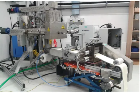
The final aspect of the meltblown line is presented in Figure 3.ii.
Chapter 3. Experimental work
33
The cleaning stage is very important, especially for spinnerets, meltblown and spunbond dies, considering the microscale of the fibers produced. For that, a proper machine is used: Schwing Fuid Technik GmbH Innovaclean, which is shown in the following Figure 3.iii.
Figure 3. iii Thermal cleaning machine
This is a thermal cleaning machine of metal parts and tools using fluidized bed pyrolysis system which removes all polymers quickly and reliably from the tools and components, by thermally degradation (the machine heat the parts around 450°C).
The conditions in the laboratory were with relative humidity of 29% and temperature around 23°C. The experimental parameters maintained constant are summarized in the Table 3.i.
Table 3. i Constant parameters in meltblowing production
Parameters Units Value
Callendar roll temperature top °C 100
bottom °C 100 Melt pump B °C 215 Melt pump A °C 215 Extruder A zone 1 °C 200 zone 2 °C 205 zone 3 °C 215 Extruder B zone 1 °C 200 zone 2 °C 205 zone 3 °C 215 Spinhead °C 215 Packwell °C 215
Chapter 3. Experimental work
34
In the following topics are described the differences between processing parameters A and B (different dies), as well as some details about each processing stage.
In both processing there were three parameters machine changed: air flow, air temperature and die-to-collector (DCD) distance. In Figure 3.iv is visible the two changes in the last parameter – DCD.
Figure 3. iv Two states of DCD setting machine a) lower level, b) higher level
Processing A
The plates system used in Die A is shown in Figure 3.v. They had 25HPI configuration with sheath-core fiber structure. Which means that the plates with 100 mm wide have 25 holes/1 inch (1inch ≈ 25,4 mm).
Figure 3. v Die A plates system configuration
The conditions used and all samples produced during all this processing are given in the Appendix II. The designation and conditions of the analyzed samples are given in the next Table 3.ii.
Chapter 3. Experimental work
35
Table 3. ii Processing A samples conditions
During this processing almost all samples were taken with good quality. In Figure 3.vi is shown one random sample collected during this processing.
Figure 3. vi Piece of a meltblown web
The minimum air temperature used was about 150°C, and with that it appears in the web some points of material, probably because it solidifies earlier; so it is not indicated to use so low temperatures.
Processing B
The plates system used in Die B were 100HPI sheath-core, and are presented in Figure 3.vii, detailing the reference configuration.
Run
order Sample ID
Operational variables
Air flow Air temperature DCD
psi °C cm 1 1A 10 200 13 3 2A 20 200 13 5 3A 10 225 13 7 4A 20 225 13 9 5A 10 225 3 11 6A 20 225 3 13 7A 10 200 3 15 8A 20 200 3
Chapter 3. Experimental work
36
Figure 3. vii Die B plates system configuration
All samples produced and their conditions are given in the Appendix III. The designation and conditions of the analyzed samples are given in the next Table x.
Table 3. iii Processing B samples conditions
Run
order Sample ID
Operational variables
Air flow Air
temperature DCD psi °C cm 1 3B 10 225 13 3 4B 20 225 13 5 5B 10 225 3 7 6B 20 225 3 9 7B 10 200 3 11 8B 20 200 3 13 1B 10 200 13 15 2B 20 200 13
During this processing the webs produced have many defects and bad quality. The material was coming out not only from the spinneret (like it was supposed to be), but also from the borders of the die. Maybe during the die installation some small gaps were left, and as the pressure used is very high, this singularity shown in Figure 3.viii happened.
Chapter 3. Experimental work
37
Figure 3. viii Problems occurring in processing B
3.3. CHARACTERIZATION TECHNIQUES
3.3.1. Density and thickness
The basis weight (w) of nonwovens is expressed in grams per square meter. It was determined weighting pieces of 5x5cm from the nonwoven media samples. The average of the fabrics weight is calculated according the following formula:
𝑤(𝑔/𝑚2) = 𝑚/𝐴 where 𝑚 is the mass of each sample and 𝐴 the area of each sample.
The density each sample is the weight per unit volume of fabric, and it equals measured weight per unit area divided by the measured thickness of fabric. This measure is more important than the thickness and basis weight to analyze the filtration efficiency.
To measure thickness was used the Microscop Phenon PRO (shown in Figure 3.ix) is equipped with high-sensitivity backscattered electron detector (both compositional and topographical modes) and a high brightness source. The zoom functionality and extremely low sample loading time narrows the gap between optical and SEM imaging. It offers wide magnification range. [22]
Chapter 3. Experimental work
38
The sample preparation passes for cutting a very small piece of the web, and use carbon tape and metal holders to fix the sample in a vertical position, in order to take picture of the thickness and not of the surface. In Figure 3.x is visible this sample holder.
Figure 3. x Sample holder
The microscope has an analysis software which allow take measurements from the pictures. The average of three or more points measured was the thickness determined.
3.3.2. Scanning electron microscope
Scanning electron microscope (SEM) is a microscope technique that allows an optical analysis better than in optical microscope. In this technique the sample is submitted to an inert atmosphere and at room temperature. It visualizes the surface of three-dimensional objects. It is possible change the detector depending in what you pretend to obtain.
All samples were mounted to aluminum sample holders using carbon adhesive tape. In order to obtain better quality and contrast on the images, the samples were coated in gold-palladium using the equipment Polaron Range, shown in Figure 3.xi. This thin layer acts like an electrical wire, drawing away the electrons that are bombarding the sample.
Chapter 3. Experimental work
39
The equipment Vegan LMU is presented in Figure X. Pictures were taken with resolutions: [768x768] and [4096x4096], and different magnifications: 350x, 500x, 1000x, using SE detector (topographic surface).
Figure 3. xii SEM microscope [23]
After taking pictures, they were edited with gama value of 2,5, then flat correction was applied to obtain black and white pictures. In the Figure 3.xiii is shown two pictures before and after correction.
Figure 3. xiii Correction applied in SEM pictures
Before the correction is visible some fibers have different grey tonalities, because they are in different layers. With this correction is tried to put all fibers in white and holes in black, with no intermediate tonalities, to get an easier and more efficient analyze.
3.3.3. Differential Scanning Calorimetry
Differential Scanning Calorimetry (DSC) is a method where heat absorption of a sample compared with a blank reference is measured, providing quantitative and qualitative data on endothermic (heat absorption) and exothermic (heat generating) processes [35].
Chapter 3. Experimental work
40
The sample is put in a pan and this is, with an empty reference pan, placed on a symmetric platform. Both are under a nitrogen atmosphere which ensures that the samples do not burn. Heat flow is measured by comparing the difference in required energy to achieve the same change in temperature across the sample and the reference [35].
This method allows the quantification of melting temperature (Tm), glass transition temperature (Tg),
crystalline phase transition temperature and energy, specific heat or heat capacity, crystallization. In this work this test was used to determine percentage of crystallinity.
DSC tests were carried out on a Mettler Toledo Simultaneous thermal analysis TGA/DSC, shown in Figure 3. Xiv, and temperature changed from 25°C to 210°C. The software analysis used measure automatically determine percentage of crystallinity, it was only necessary introduce the theoretical value of polypropylene (207 J/g).
Figure 3. xiv DSC equipment
3.3.4. Optical microscope
Digital optical microscope Leica microscope, shown in Figure 3. Xv, with large working distance with magnification from 20 to 400x. The microscope with the software enables producing depth-of-focus images, distance measurements, profiling and 2D and 3D mapping, works with diffuse light, polarized light and allows oblique view. [22]


![Figure 2. iii Drylaid formation processes: a) carding, b) air-laying [29]](https://thumb-eu.123doks.com/thumbv2/123dok_br/17228175.786867/25.918.254.673.651.950/figure-iii-drylaid-formation-processes-carding-air-laying.webp)
![Figure 2. v Melt spinning formation processes: a) meltblowing, b) spunbonding [29]](https://thumb-eu.123doks.com/thumbv2/123dok_br/17228175.786867/26.918.258.664.606.973/figure-v-melt-spinning-formation-processes-meltblowing-spunbonding.webp)

![Figure 2. ix 3D scheme of part of the die and respectively cross section [36]](https://thumb-eu.123doks.com/thumbv2/123dok_br/17228175.786867/31.918.228.725.495.709/figure-ix-d-scheme-die-respectively-cross-section.webp)
![Figure 2. xi Filtration efficiency curve [39]](https://thumb-eu.123doks.com/thumbv2/123dok_br/17228175.786867/41.918.195.715.327.674/figure-xi-filtration-efficiency-curve.webp)
![Figure 2. xii SEM picture of top surface of a sample after filtration [40]](https://thumb-eu.123doks.com/thumbv2/123dok_br/17228175.786867/42.918.280.642.115.369/figure-xii-sem-picture-surface-sample-after-filtration.webp)