Internship Report
Master in Product Design Engineering
Industrial Project of Metallurgical Structures
Naveen Bharadwaj D N
Internship Report
Master in Product Design Engineering
Projecto Industrial de Estruturas Metalúrgicas
Naveen Bharadwaj D N
Dissertation/Report developed under the supervision of Doctor Carlos Capela, Professor at the School of Technology and Management of the Polytechnic Institute of Leiria and co-supervision of Doctor Henrique Amorim Almeida, professor at the School of Technology and Management of the Polytechnic Institute of Leiria.
ii
iii
Acknowledgement
I am very thankful to Electrofer Grupo for having given me an opportunity to undertake my curriculum internship at their prestegious organization. It was a very good learning experience for me , so I could get exposed to an industry that involved variety of unique construction practices and challenges. I would like to convey my heartfelt thanks to
Mr. Jose G.M. Gregorio, Managing Director and Mrs. Sara Verde, Director Human
Resources who heartily welcomed me for the internship. I express my deep sense of gratitude to Mr. Joao Marques, Director Quality Department, who was the supervisor of my intership and the one who guided me through out my internship and who provided sincere supervision during the works of my internship. I would also like to thank all the department heads of Electrofer Grupo for training me by spending their valuable time and by giving me good guidance during my internship programme.
I owe my whole hearted thanks to all the staff of Electrofer Grupo for being so helpful during the phase of my internship.
I want to give special thanks to Prof. Carlos Capela and Prof. Henrique Amorim
Almeida, proferrsors of the School of Technology and Management at polytechnic
Institute of Leiria for their required support and encouragement.
I am also thankful to my parents who have always been as a source of inspiration and motivation for me.
I hope that I can build upon the experience and knowledge that I have gained and make a valuable contribution towards the Enterprise in coming future.
Last but not the least, I have tried my heart and soul to write the report accurately, however there might be some errors and impracticle mistakes due to my aptitude and time constraints. In this regard, I request your good-self to seek your kind consideration as I am in the process of learning.
iv
v
Resumo
O relatório de estágio é um amplo espectro dos trabalhos de estágio em que tento explicar a experiência da minha empresa de hospedagem de estágio (Electrofer Grupo). Este relatório é amplamente construído com aspectos teóricos e práticos do trabalho de construção que é realizado na organização.
Depois de ter um curso de curso intensivo, procurei ter um estágio em uma empresa de construção metálica para obter experiência prática e familiaridade com a construção de estruturas de aço. Para o segundo ano de Mestrado em Engenharia de Design de Produto, realizei estágio no Electrofer Grupo. Esta empresa tem uma importância fundamental na construção de obras de aço e tem uma das maiores unidades de produção em todo o país que funciona em várias regiões para produzir estruturas de aço.
Este relatório consiste em muitos capítulos que são escritos de acordo com cada estágio do meu estágio. A primeira fase do meu estágio iniciou-se no departamento de preparação e posteriormente foi seguida por Qualidade, Produção, Pintura, Gestão Comercial e de Construção.
Por isso, este relatório é uma coleção de todas as obras de diferentes departamentos envolvidos na produção de aço. No que diz respeito à minha preocupação com este estágio, ganhei muita visão sobre como usar o conhecimento teórico aplicável em conformidades práticas.
Tenho certeza de que, com essas habilidades profissionais com abordagem teórica e prática, poderei usá-las para ganhar meu potencial para realizar trabalhos industriais com os aspectos de qualidade.
vi
Abstract
The internship report is a broad spectrum of the works of internship in which I try to explain the experience of my internship hosting company (Electrofer Grupo). This report is broadly constructed with theoretical and practical aspects of the constructional work that is carried out in the organization.
After having intensive course work, I looked upon to have internship in a metallic construction company in order to get practical experience and familiarity with the construction of steel structures. For the second year of Master´s Degree in Product Design Engineering I took internship in Electrofer Grupo. This company owes a pivotal importance in the construction of Steel works and has one of the largest production units in whole of Portugal functioning in various regions to produce steel structures.
This report consists of many chapters that are written according to each stages of my internship. The first phase of my internship started in the department of preparation and later it was followed by Quality, Production, Painting, Commercial and Construction Management.
Hence, this report is a collection of all the works of different departments that is involved in the production of steel works. As far as my concern with this internship, I gained much insight into how to make use of theoretical knowledge applicable in practical conformities.
I am sure that with these professional skills with theoretical and practical approach, I will be able to use them to gain my potential towards to carry out industrial works with the aspects of quality.
viii
ix
List of figures
Figure 1: Electrofer General Organization Structure ... 4
Figure 2: Grid dialog box ... 8
Figure 3: Reference model imported from 2D software ... 9
Figure 4: Grid values for modelling silos and its structures ... 10
Figure 5: Detailing for pad footings ... 10
Figure 6: Footings for silos and columns ... 11
Figure 7: Column properties dialog box ... 11
Figure 8: Silos and its structures ... 12
Figure 9: Placement of beams over the silos ... 12
Figure 10: Construction of slabs on the beams ... 13
Figure 11: Structure modelled to assemble with the structure of silos ... 13
Figure 12: Change Phase1 to Model1 ... 14
Figure 13: Assembly selection dialog box ... 14
Figure 14: The completed model of silos and its structuresa. ... 15
Figure 15: Exercise for placement of bolts ... 15
Figure 16: Grid Values to model a Steel container ... 17
Figure 17: Top view of grid for Steel container ... 17
Figure 18: Stiffeners ... 18
Figure 19: Cuts for welds ... 18
Figure 20: Completed model of Steel container ... 19
Figure 21: Grid values for Bridge ... 20
Figure 22: Base of the Bridge Structure ... 20
Figure 23: Shoulders for supporting pedestrian’s passage ... 21
Figure 24: Barriers attached to the shoulder ... 21
Figure 25: Side view of the arch for bridge ... 22
Figure 26: The surface view of the arch ... 22
Figure 27: Completed model of the bridge ... 23
Figure 28: Beam properties dialog box to name prefixes ... 23
Figure 29: Numbering of the parts ... 24
Figure 30: Parts converted to 2D drawing for manufacturing ... 24
Figure 31: ITP reference document for steel structures ... 27
Figure 33: ITP reference document for steel structures ... 28
Figure 34: Recommended matrix for determination of execution classes ... 29
Figure 35: Metal Active Gas welding, process 135 ... 30
Figure 36: Flux Cored Arc Welding, process 136... 31
Figure 37: Submerged Arc Welding, process 121 ... 31
Figure 38: Drawn arc stud welding with ceramic ferrule, process 783 ... 32
Figure 39: Shielded Metal Arc Welding, process 111 ... 32
Figure 40: Various positions that a welding can be made ... 33
x
Figure 42: Fillet welding terms ... 35
Figure 43: Digital throat weld measuring gauge ... 35
Figure 44: Leg-length measuring cam type gauge ... 35
Figure 45: Ultrasonic test equipment ... 36
Figure 46: Couplant applied on the weld part ... 37
Figure 47: Magnetic particle testing ... 37
Figure 48: Arrangement of plates for CNC cut ... 40
Figure 49: Plasma cut ... 41
Figure 50: Section plate cutting machine ... 42
Figure 51: Drilling machine ... 43
Figure 52: Bending machine ... 43
Figure 53: Flux cored arc welding ... 44
Figure 54: Flux cored arc welding machine ... 44
Figure 55: Submerged Arc welding process ... 45
Figure 56: Shielded metal arc welding process ... 46
Figure 57: Hot dip galvanizing process ... 47
Figure 58: Uniform corrosion on steel ... 50
Figure 59: Crevice corrosion ... 51
Figure 60: Pitting corrosion ... 51
Figure 61: Erosion corrosion in a tube wall ... 52
Figure 62: Corrosion products will have volumes higher than steel and cause deformation ... 53
Figure 63: Sharp edges to be rounded to obtain uniform and thick paint coat thickness ... 53
Figure 64: Right angled bends to be eliminated to avoid turbulance which may cause corrosio 54 Figure 65: Cathodic protection ... 55
Figure 66: Peeling of paint ... 59
Figure 67: Saponification ... 60
Figure 68: Blistering due to entrapped air or solvents in the coating ... 60
Figure 69: Formation of craters ... 61
Figure 70: Cracking of paints ... 61
Figure 71: Solvents disappearing from the spray before it reaches the surface ... 62
Figure 72: Orange peel ... 62
Figure 73: Copy of a daily log report ... 69
Figure 74: Wet film thickness measuring guage ... 73
Figure 75: Wheel guage to measure wet film thickness ... 73
Figure 76: Magnetic induction instrument ... 74
Figure 77: Magnetic pull off instrument for measuring dry film thickness ... 75
Figure 78: Structural Organization of Commercial department in Electrofer Grupo ... 77
Figure 79: Activities of commercial management ... 78
Figure 80: Characteristics of buyer seller relationships ... 80
Figure 81: Budget preparation flow chart ... 81
Figure 82: Cash flow budget analysis (quarterly) ... 82
Figure 83: Sample cost estimation for site, footings and foundations ... 83
Figure 84: Construction Management organizational structure ... 84
xi
Figure 86: Steps involved in collecting datas, choosing methods and planning for data processing
and analysis ... 87
Figure 87: Flowchart for the developement of a project ... 89
Figure 88: Factors affecting initial cost of the project ... 91
xii
xiii
List of tables
Table 1: Atmospheric corrosivity categories and their influence on typical environments ... 62 Table 2: Daily record for paint applications ... 68
xiv
xv
List of
acronyms
CAD Computer Aided Design
QA Quality Assurance
QC Quality Control
ITP Inspection and Test Plan
CEN European Commitee for Standardization
CENELEC European Committee for Electrotechnical Standardization ANSI American Institute of Standard Institute
AWS American Welding Society
NDT Non-Destructive Testing
ISO International Organization for Standards
SC Service Category
PC Production Category
CC Consequence Class
EXC Execution Class
MAG Metal Active Gas
GMAW Gas Metal Arc Welding
MIG Metal Inert Gas
CO2 Carbon di Oxide
FCAW Flux Cored Arc Welding
SAW Submerged Arc Welding
SMAW Shielded Metal Arc Welding
MHz Mega Hertz
xvi
CNC Computer Numeric Control
PVC Pigment Volume Concentration
Sa Sand Blasting
St Hand and Power Tool Cleaning
F1 Flame Cleaning
BOQ Bill of Quantities
xvii
xviii
Table of Contents
ACKNOWLEDGEMENT III RESUMO V ABSTRACT VII LIST OF FIGURES IX
LIST OF TABLES XIII
LIST OF ACRONYMS XV
TABLE OF CONTENTS XVIII
1. INTRODUCTION 1
1.1. Sections of the company I had been working ... 1
2. ABOUT THE ORGANIZATION 3 2.1. Structure of the organization... 4
2.2. Quality Policy ... 5
2.3. Environment, Health and safety policy ... 5
2.4. HR policy ... 5
2.5. Work Culture ... 6
2.6. Vision ... 6
xix
3. DEPARTMENT OF PREPARATION 7
3.1. Modelling with Tekla Structures ... 7
3.2. Training on Tekla Structures... 7
3.3. Experience while on Tekla Structures ... 9
3.4. Placement of bolts ... 15
3.5. Working on Project 1 (Steel Container) ... 16
3.6. Working on Project 2 (Bridge) ... 19
3.7. Drawing ... 23
4. DEPARTMENT OF QUALITY 25 4.1. Quality Testing ... 25
4.2. Role of quality assurance Manager ... 25
4.3. Inspection and Test Plan ... 26
4.4. Welding Process used in Electrofer ... 30
4.5. Welding positions ... 32
4.6. Welding inspection ... 33
4.7. Ultrasonic inspection ... 36
4.8. Magnetic Particle inspection ... 37
5. DEPARTMENT OF PRODUCTION 38 5.1. Production ... 38
5.2. Production Procedure ... 39
5.2.1. Design for economic production ... 39
5.2.2. Cut optimization ... 40
xx
6. DEPARTMENT OF PAINTING 49
6.1. Introduction to painting ... 49
6.2. Corrosion ... 49
6.3. Protection against Corrosion ... 52
6.4. Protection coatings ... 55
6.5. Composition of paints ... 56
6.6. Types of paints ... 57
6.7. Paint Coating failures ... 58
6.8. Painting Standards ... 63
6.9. Procedures and documentations ... 66
6.10. Inspection... 70
6.11. Overview of the chapter ... 75
7. DEPARTMENT OF COMMERCIAL 77
7.1. Commercial Management ... 77
7.2. Commercial Relationships ... 78
7.3. Role of budgeting in Management planning ... 80
7.4. Understanding cash flow ... 81
7.5. Estimation in construction Industry ... 82
8. DEPARTMENT OF CONSTRUCTION PROJECT MANAGEMENT 84
8.1. Construction Management (CM) ... 84
8.2. Construction Management Chart ... 84
8.3. Mission of Construction Management Department in Electrofer ... 84
xxi
8.5. Assessment Plan ... 85
8.6. Developement of a project by Project Manager ... 88
8.7. Budgeting for the assessment ... 89
8.8. Project Execution ... 92
CONCLUSION 93
1
1. Introduction
Since, I finished first year of my Master´s in Product Design Engineering. I wished to take up Internship for the second year works. So, I was searching for an internship in the companies that deals with Energy conversion or industry that deals with the construction of metallic components. When I was searching internships in these fields I was not able to search one that suits my área of interest. Later, I requested my Professors to find an internship for me in any of these fields. Later, my Professors explained me about Electrofer Grupo that deals with construction of Metallic components and surface treatment.
On later stages, the company accepted me to do internship in various áreas that existed in the company. I really liked the work culture of this enterprise; everyone encouraged me to learn different strategies of applictions that existed in their department. All the doubts I had were clearly expained by the representatives of every department without hesitation. The Director of Quality department and my internship supervisor Mr. Joao Marques gave me in-depth knowedge of welds and standards that are used to produce construction materials. In similar fashion, all the representatives of different departments gave an insight clear idea about the information about the functions and the importance of their department that is responsible to carry out overall activities to achieve organizational goals. All the information that I collected from every deartment and the works that I have carried out during my internship are explained in my report.
In this, I try to explain my nine months work that I progressed in different departments of my internship hosting company (Electrofer Grupo). The report is broadly constructed with theoretical and practical aspects of the constructional work that is carried out in the organization. This report consists of many chapters that is written according to each stages of my internship.
1.1. Sections of the company I had been working
The first phase of my internship started at the department of preparation and later it was followed by Quality, Production, Painting, Commercial and Construction Management.
Department of preparation: In this department, training was given on using Tekla Structures, a building information modelling software. In hte beginning stage, I was thought how to visualize drawings and plot them on the software. After learning the
2 software, I could freely experiment designing different steel structures and in the first chapter, I have clearly discussed the things that I have learnt in this department.
Department of Quality: In this department, training was given to formulate inspection and test plans and how to execute them for producing quality products. Thorough training was given to visualize welds according to Europen and American standards. In second chapter, all the details that is related to welding and producing constructional structures according to the European and American standards are discussed.
Department of Production: In the department of production, training was given on all the productional aspects of constructional structures.
Department of Painting: In the department of painting, theoretical aspects of different rust grades of steel and protection of steel from corrosion were explained. Selection of paints according to the standards for corrosion protection and environment were explained.
Department of Commercial: The relationship management with the customers were thought. Suituational analysis of marketing plan, budgeting and tender estimation was thought.
Department of Construction Management: In this department, selection of materials,construction budget etc were learnt.3
2. About the organization
Electrofer Grupo is the biggest legacy of a Portuguese Entrepreneur, Mr. José Gregório e Joaquim Fernandes, who built a heritage that facilitates Metallic Constructional Works. Electrofer Grupo is a world class organization which has successful erected beautiful complex structures all over the world and now is a leader in construction of steel structures. Their erections included pedestrian bridges, steel bridges, railway bridges, steel stanchions, steel structures, communication towers, slab support structures, modular housing projects, auxilary towers, structures for swimming pools, factories, logistic centres, shopping malls, biodoesel power plants, roads and railway support equipments, football stadiums, acoustic barriers etc. All these erections were so successful because of the perseverence and dedication towards the quality of work.
Address: Rua Casal de Lebre No45, Apart. 605 2430-446 Marinha grande
Portugal
Telephone: +351- 244 570 500
+351-244 570 509
Electrofer Grupo was founded in the year 1985 with an objective to produce metal strucutres to electricity networks for mid and low voltages. Later, Electrofer expanded their business and they expanded their business towards public works and anti-corrosion protction. By this, Electrofer II and Electrofer IV were born. Electrofer II produce steel structures and Electrofer IV deals with surface treatment. These two companies join together to make services to Electrofer Grupo.
Electrofer Grupo is EN ISO 9001 Quality Certified Company and now Electrofer has launched Execution Class IV for the construction of special structures.
4
2.1. Structure of the organization
5
2.2.
Quality Policy
Electrofer quality policy has the ultimate goal of satisfying their customers. Electrofer´s quality policies are defined as:
Careful customer care
Effective and efficient work management Meet customer requirements
Have motivated and satisfied employees
Electrofer quality policy explains that these four points are the subject of a continuous process of evaluation and improvement.
2.3.
Environment, Health and safety policy
At Electrofer Grupo, health and safety are given with the highest priority. The policy enunciated by the management of Electrofer lays emphasis on environment, health and safety through structured approaches and well defined practices. Electrofer´s Environemnt, Health and Safety objectives include:
Ensure working conditions that safeguard the safety and physical and mental health of workers.
Prevent accidents at work.
Develope the technical conditions that ensure the application of measures to prevent accidents at work.
Inform and train workers in the field of occupational safety and health.
Managing stocks and purchasing personal protective equipment.
Manage cleaning and building maintenance
Execution of poilicies to prevent occupational risks;
Compliance with legistlation on occupational safety and health.
2.4.
HR policy
We at Electrofer Grupo believe that people are our most valuable resource and play a vital role in helping us realize our vision. We are commited to:
Manage the difference between the expectations of employees and the reality in wages and employment stability.
Ensure compliance with all processes that affect you, in a precise and timely manner
Fulfill all your goals efficiently, with the least waste of time and money.
To answer all the doubts of employees who fit into the field of human resources.
6
2.5.
Work Culture
Work culture emphasises:
Continuous learning and training
Degree of transparency and clarity is very high
Freedom to experiment
Quality of work
Customer loyalty
Employee engagement
2.6.
Vision
To be the leader in the market of Metallic Constructions continuously competing with the aim of improving more.
2.7.
Mission
To contribute to the innovation, growth and competitiveness of the metal mechanical industry, in parallel with the defence of the legitimitate interests of share holders and financiers.
7
3. Department of Preparation
3.1.
Modelling with Tekla Structures
Tekla Structures is building information modeling software that helps us in modeling structures using different kinds of building materials like steel and concrete. Tekla allows the engineers, drafters to structure the design of a building in 3D, access the information of the structure and also to generate 2D drawings. Tekla has a user friendly manual that helps a beginner to learn and use variety of tools in the software. Tekla also have another manual named First steps with Tekla structures, it is an interactive tutorial, where they help the beginner to build a complete structure with step by step information. After completing the basic trainings, I was very confident to build a small project according to proper dimensions and assemble them.
Later, I was thought how to read the details of the drawing and model a structure using those details. After the basic model was structured using the details; I was given with three projects, where I had to design a structure and compare it with the models that were already designed. This training boosted the level of my confidence; the cuts for welds, placement of bolts in proper orientation, to place the beam in angular positions, the attachment of stiffeners etc all these important detailing were thought. So, the structures I modeled could be ready for manufacturing as well.
3.2.
Training on Tekla Structures
i. Before starting any project on Tekla Structures, the details of the drawing are analyzed first. Analysis of the drawing is done by going through the detailing of the structure completely (i.e. analyzing the dimensions, section detailing, type of profile, material used and visualizing the structure in 3D form.
ii. We open the Tekla Structure software. Then we login into the software by filling up the parameters by selecting the environment, role and configuration and by clicking ok. When Tekla structure starts, Welcome to Tekla Structure dialog box appears.
The dialog box contains some useful links and at the bottom of the links we select na option whether to create a new model or to open an existing model.
8
If a new model is selected the parameters has to filled and has to be saved in the directory.
If an existing model is selected a dialog box opens to choose the model that we had saved before.
iii. After choosing an option, Tekla guides us on to a modeling platform. Modeling platform will have an automatically generated grid.
iv. Now select file and click on select project properties in the drop down menu. In project properties toolbar, fill in all the fields required.
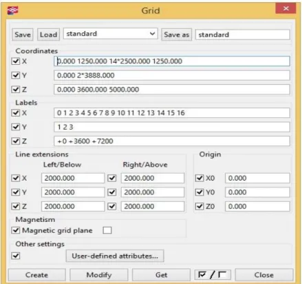
v. According to the details in the drawing sheet the grid is plotted. The grid is the base outline for any structure because the complete structure is modeled on the grid. The grid can be changed by altering the parameters in X, Y, Z Coordinates and by altering the values in the labels.
Figure 2: Grid dialog box (Structures, Tekla.)
vi. The beams or columns can be directly plotted according to the draft dimensions or it can be plotted on the reference model that is imported.
vii. It is also possible to import a reference model from AutoCAD or from other 2D modeling software (Note: The reference model has to be scaled before or after importing into Tekla Structures). It is always better to scale the drawing in a 2D modeling software and save it in a folder.
9 viii. Click on create view using two points - choose the view according to the direction of the model to be designed. Another window opens with the direction of the selected view. Select plane parallel to view plane and place the plane on the start point of the model to be designed.
ix. To import the saved reference model, click on file - select insert reference model - reference model properties dialogue box appears on the screen - in the file name option click on browse and select the saved reference model and change scale 1:1. Click on modify. Place the cursor on the origin of the selected view. The reference model will be placed on the selected view. Now the selected view can be closed. x. The reference model can also be adjusted to the required position by selecting the
model and right clicking the mouse button and by selecting the move option the reference model can be placed to the required position.
xi. The beams or columns can be plotted on the reference model for quick modeling of the structure.
Figure 3: Reference model imported from 2D software (Structures, Tekla.)
3.3.
Experience while on Tekla Structures
Modeling of Silos and it´s structures:Modeling of Silos with structures is an interactive training with Tekla Structures. This training is very important for a beginner because a beginner will understand how to start a project and end them. In this interactive training, the manual will give an idea about how to alter grids, how the foundations are laid, how the beams and columns can be placed in different angles, formation of roofs, placement of hinges and assembling the projects. Steps for modeling the Silos and it´s structures:
10 o The existing grid has to be modified by double clicking the grid and by completing the grid dialog box as shown below by entering the values in X, Y, Z co-ordinates and labels for the grid lines.
o Click on modify and apply.
o Enter a name in the box next to Save as and click on Save as to save the grid values for later use.
Figure 4: Grid values for modelling silos and its structures (Structures, Tekla.)
o After modifying the grid, foundations are laid as per the general drawing shown below. Foundations for silos are also made according to the general drawing.
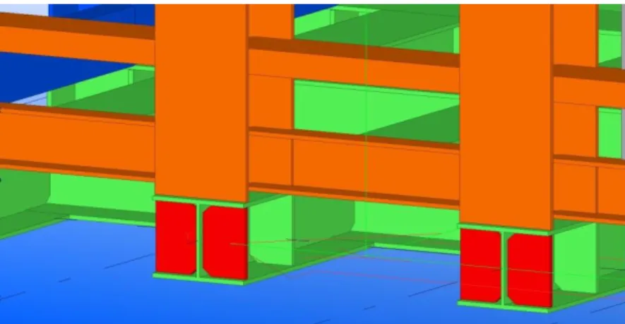
11 To create the concrete footings, double click on the create pad footing icon, complete the required fields. Click on modify and apply. Place the footings on A1 and B1 (note: The footings have different values).Footings for Silos is made by changing the profile to circular. To translate the footings on the grid, select the footings - right click - copy special - select linear - enter the distance in X - enter the number of copies. Before copying, it is important to check whether the work plane is on the origin.
Now, the footings will look like those shown below:
Figure 6: Footings for silos and columns (Structures, Tekla.)
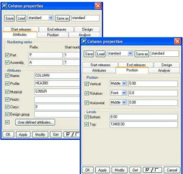
o Steel columns and Concrete Silos are laid on the concrete footings. Like the previous step, we first lay first two columns and copy linear to create other columns. To create columns, Double click on create column- Column properties dialog box opens - complete the table - click modify and apply. To create Silos double click on concrete column - select circular profile and enter the diameter - Select the centre of the silo footings - the silos will be created.
12 Pick the intersection of grid A-1to create one column and pick the grid B-1 to create the second column. Select the columns and copy on to other footings as explained before. Now the Silos and columns will look like those shown below.
Figure 8: Silos and its structures (Structures, Tekla.)
The beams are placed according to the general drawing. To create beams- double click on create beam icon - beam properties dialog box opens - complete the table - click modify and apply. Select the columns accordingly where the beams are to be placed. The structures of beams are created. The height can be adjusted by moving the beam. The beams will look like those shown below.
13 Concrete core hollow slabs are created on the beams. To create slabs - double click on create concrete slab icon - Concrete slab properties dialog box opens - complete the fields - click modify and apply - select four closed points on the beams - Slabs are created. Click on slab and right click to copy - select a corner point and place on the required place. Concrete slabs are created.
Figure 10: Construction of slabs on the beams (Structures, Tekla.)
o Similarly another structure is created with columns, beams and concrete slabs as shown below and is assembled to the above structure.
Figure 11: Structure modelled to assemble with the structure of silos (Structures, Tekla.)
To assemble the structures, click on tools - select phase manager - select phase 1 - click objects by phases. All the parts in the model get highlighted, indicating they belong to phase1. Now change the phase name to Model1.
14
Figure 12: Change Phase1 to Model1 (Structures, Tekla.)
Now click Edit - copy special - open from new model - select the second saved structure - enter 1 in the phase number from which to copy the objects - click copy - the model1 parts will now be a combined model.
Figure 13: Assembly selection dialog box (Structures, Tekla.)
15
Figure 14: The completed model of silos and its structures (Structures, Tekla.)
3.4.
Placement of bolts
The basic model training was completed by interacting with Tekla basic model training tutorial. After the completion of the model training, it was time to enter into projects. I was asked to complete some projects during the phase of my training in design. Before starting the projects an additional training was given to place the bolts in proper orientations and to detail the bolt parts.
16 Steps to place the bolts:
i.
Double click the create bolts option. Fill in the required details. Select the bolt size, bolt standard etc. In the bolt group the shape can be selected whether the bolt has to be placed in array or circle or XY list and the distance of bolts can be adjusted by altering the values in Bolt distance X and Y. The position of the bolts can also be altered by altering different position tabs on plane or rotation or at depth. The washers, nuts, slotted holes can be selected by highlighting the empty boxes of the diagram present in the Bolt properties dialog box. Click on modify and apply.ii.
Now select the plate that has to be bolted and click on the middle mouse to set theorientation of the placement of the bolts and select the start and the end points. The bolts will be placed on the part depending on the orientation of selection.
iii.
It is a very important to give detailing to the bolt. Select the Detailing option on the upper task bar - select bolts - edit bolted parts - select the bolts and click on the parts where the bolt has to enter and click on the middle mouse button. The bolts will be placed on the parts exactly.3.5.
Working on Project 1 (Steel Container)
My first project on Tekla was to construct a Steel Container. General drawing was given with detailing to construct the project. I had to construct a steel container on Tekla Structures for manufacturing purpose based on the details in the general drawing. In the beginning, it was important for me to understand the drawing as per the details in the drawing sheet. It was also very important to give cuts for the welds.
Steps followed to construct the Steel Container:
A new model was created and saved the file into a folder. A new model opens with an in-built grid.
The grid was modified by entering the values in the co-ordinates and labels as shown below.
17
Figure 16: Grid Values to model a Steel container (Structures, Tekla.)
The grid will look like those in the diagram below.
Figure 17: Top view of grid for Steel container (Structures, Tekla.)
HEA200 beam profile is used as the base of the steel container. The selection of the beam profile and material has been explained while sharing the information in experience while working on Tekla Structures. The stiffeners are placed at the edges of the beams on either side. To select stiffeners click on component catalog - select stiffeners on the store - the stiffener parameters can be changed by double clicking the selected stiffener - place it on the required position, the stiffener will automatically place on the selected part. The red color part in the below diagram represent the stiffeners.
18
Figure 18: Stiffeners (Structures, Tekla.)
Similarly, the beams and columns are created as per the general drawing to complete the Steel Container. One side of the grid is created perfectly and is copy translated according to the dimensions.
The cuts for welds are given according to the profile of the part selected, a small structural catalog will have the complete information about the type of profiles, and based on the radius of the material the cuts for welds are given.
Figure 19: Cuts for welds (Structures, Tekla.)
The parts are weld at the required places. Verification of welds is done by holding the ctrl+alt button and selecting the part.
19
Figure 20: Completed model of Steel container (Structures, Tekla.)
3.6.
Working on Project 2 (Bridge)
Bridge project was a challenging task because there were many detailing and had to carefully cut the beams in particular angles, cuts for welds were to be given, placement of bolts and the application of reinforcement was also important. The bridge project was an important task because many other important tools which I was not familiarized in the previous concepts. For example: i. the use of Macros to view any surface was a very important tool, this tool made it very convenient for me to create a view for any surface on the bridge; ii. To measure the distance of bolts (there is a special tool to measure the bolt spacing's); iii. Use of filters; iv. Creating report.
Steps followed while constructing the bridge:
The basic step to construct any structure on Tekla is the modification of the grid according to the detailing on the general drawing. The grid was modified by altering the values and co-ordinates as shown below.
20
Figure 21: Grid values for Bridge (Structures, Tekla.)
The construction of the bridge started by importing a scaled 2D AutoCAD drawing into Tekla structures. The steps for importing the saved 2D models into Tekla structures have been explained previously.
HEB300 profile type of beam was used as the base of the bridge. But there was a small problem, the beam was supposed to be made tapered. If the beam has to be cut to make tapered then there will be loss of material, instead a plate profile was selected with the profile as mentioned in the general drawing and the plate was converted as a beam to reduce the loss of material. And the connectors were fixed on top of the beam to support the concrete. Connectors are also attached the same way as bolts but while selecting the bolt standard Connector has to be selected.
Figure 22: Base of the Bridge Structure (Structures, Tekla.)
This tapered plate was cut, welded and attached perfectly, since it is a base and it takes the whole weight of the bridge, it has to be perfectly strong. Later, the base was copied and translated according to the distance mentioned in the general drawing.
21 Shoulders to support the pedestrian passage were bolted to the base of the beam. HEA100 profile was used to construct the shoulder. The shoulders were constructed by cutting the beam angularly and welding at their corners and bolting the complete structure to the base of the beam.
Figure 23: Shoulders for supporting pedestrian’s passage (Structures, Tekla.)
Barriers are attached to the shoulder of the bridge. Profile IPE100 was used to create the barrier beams and barrier beams were attached to the shoulder of the beam.
22 The arch was constructed using three U-profile type beams. The arch is supported by a series of beams placed at a particular angle to support the arch on the top and is bolted to the base of the beam.
Figure 25: Side view of the arch for bridge (Structures, Tekla.)
Plates are placed in-between the beams of the arch with proper cuts for welds depending upon the profile of the material. A view of the plate placed in between the beams is shown in the figure below. The red colored material is the plate placed between three beams of the arch.
Figure 26: The surface view of the arch (Structures, Tekla.)
Parapet railings were formed on the edge of the beam base for safety purpose. Now, the complete model of the bridge is ready for the manufacturing purpose.
23 The diagram below shows the structure of the bridge.
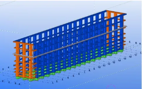
Figure 27: Completed model of the bridge (Structures, Tekla.)
3.7.
Drawing
Drawing is the next step where we convert the designed model into a drawing list which contains the complete information of the design that is required for manufacturing. Based on the results of drawing, the part is manufactured. To convert the design to drawing the following steps were followed:
i. The parts that belong to one system are grouped by assigning the same keywords to prefixes either for parts or assemblies. To assign the same keywords double-click on the part and in the numbering series column change the name of the prefixes of the parts or assemblies to the same keyword that belong to the same system.
24 Now go to drawings and reports - select numbering - select number series of selected objects.
Figure 29: Numbering of the parts (Structures, Tekla.)
ii. Again click on Drawings & Reports - select create single part drawing and after single part drawing loads click on create assembly drawing.
iii. Now click on drawing list and there would be a list of parts of the drawing set and it is also possible to view the drawing and modify the changes by clicking twice on any of the detail in the drawing list.
iv. The drawing that is required for manufacturing will be as shown below. Below drawing is an example of one of the part, there will be many drawings created and each has to be modified as required
25
4. Department of Quality
4.1.
Quality Testing
Quality testing is a way of preventing mistakes or defects in manufactured products and also ensuring that the products meet certain standards of quality. In quality testing, quality assurance and quality control plays a very important role, in fact these terms are often used interchangeably to ensure the quality of a product or service. However, these two terms have different meanings.
i. Quality Assurance (QA): It is a planned and systematic activity in a quality system to ensure the product is manufactured or serviced according to the standards of quality.
ii. Quality Control (QC): It is a process to fulfil the requirements of a quality by observation technique and systematic activity.
4.2.
Role of quality assurance Manager
Quality assurance managers works with other employees in a company to establish procedures and quality standards to fulfil the objectives of the targets by ensuring that the organization goals, efficiency and profitability are accomplished. Below are some of the roles that the quality assurance manager follows:
Process: Quality assurance manager follows certain policies and documents essential to quality assurance. Quality assurance managers prepare a set of documents to organize the plans to assign a representative for a particular job and update quality documentation based on the process on a recognised standard. Team: Quality assurance managers supervise a team of inspectors (who carry out
the detailed assessment of the production) to check whether the products or services are monitored according to the standards. Managers also recruit and train supervisors and provide them with quality guidelines to assign their day to day work.
Training: The quality assurance managers have to provide information for the employees working in the production department about the quality requirements. Quality assurance managers have to provide the training in best practices. They
26 should aim that the production employees are responsible of their duties and are working according to the quality standards.
Suppliers: Quality assurance managers have to work with the suppliers to help formulate the quality of good required. QAM should make note of all the details of the components and materials are according to the quality standards of the manufacturer.
Improvement: Quality assurance managers have to completely participate in quality improvement programs to monitor continuous improvement, aiming to reduce the number of defects and improve the levels of quality of the product to be produced.
4.3.
Inspection and Test Plan
An inspection and test plan is a document compromising of systematic detail to test a system or a component such as visual inspection, welding inspection, dimensional inspection, factory acceptance test etc. The standards of European such as CEN, CENELEC or American standards such as ANSI/AWS D1.1/D1.5 (Society, 1999) are applied for inspection and test plan in steel structure manufacturing shop. For, ITP the witness of some inspection and third party witness are mandatory and it cannot be changed (inspection-for-industry.com , 2012-2013) . There are some points that are to be checked, reviewed and clarified by the third party inspector; some of the points that are to be witnessed are as follows:
Raw material inspection, material certification document.
Welding inspection by witnessing welding addition material certification, manufacturer certificate.
Dimensional control of components – verification from the fabrication drawing, cut drawing and assembly drawing, by following general dimensional tolerances.
Surface treatment – reference documents, verifying as per the specific project document.
Painting – Inspection by testing wet and dry thickness, verifying by technical paint documentation.
27 Below is an example of ITP document for steel structure:
Figure 31: ITP reference document for steel structures (www.inspection‐ for‐ industry.com)
28
Figure 32: ITP reference document for steel structures (www.inspection‐ for‐ industry.com)
In the department of quality I was asked to learn about the European standards so it would be helpful for me to specify the requirements for execution of structural steel work as structures or as manufactured components, produced from different manufacturing techniques.
The European standards documents give us the complete information about how the steel structures are to be manufactured, their execution, delivery and identification, cutting of steel structures, dimensioning of holes, requirements for welding plan, erection methods, inspection, testing and correction etc for the countries that are bound to implement European Standards.
The Execution classes are selected according to the hazards connected with the use of the structure. The selection of the execution classes will be from the suggested criteria for different categories. The categories are explained below.
i. Suggested criteria for Service Categories – The service categories are divided as SC1 and SC2. SC1 category signifies the structures and components designed for quasi static actions only (example: buildings). SC2 category signifies the structures designed for fatigue actions (examples: roads, railway bridges, structures that are susceptible to vibrations induced by wind, crowd or rotating machinery) (Execution
29 of steel structures and aluminum structures - Part 2: Technical requirements for steel structures, August 2011).
ii. Suggested criteria for Production Categories – The production categories are divided as PC1 and PC2. PC1 category signifies the non welded components manufactured from any steel grade products, welded components manufactured from low steel grade products. PC2 atITP reference document for steel structures categories signifies the welded components manufactured from high graded steels, components that are assembled by welding on construction site, components with hot forming manufacturing(Execution of steel structures and aluminum structures - Part 2: Technical requirements for steel structures, August 2011).
iii. Consequence classes are divided as CC1, CC2 and CC3 depending upon the safety of the humans in the working environment. CC1 is referred to as less in loss of human life, Economic, social or environmental consequences are less importance or negligible. CC2 is termed as average loss of human life, Economic, social or environmental consequences are given medium importance. CC3 is termed as high in loss of human life, Economic, social or environmental consequences are given maximum importance (Execution of steel structures and aluminum structures - Part 2: Technical requirements for steel structures, August 2011).
Considering all these categories the execution classes are selected by selecting the nature of service, production and consequences of human lives in the working environment. Figure 4 is the recommended matrix for determination of execution classes.
Execution class 4 is applied to special structures or the structures with extreme consequences for structural failure as required by National provisions.
30
4.4.
Welding Process used in Electrofer
Electrofer is a metallic construction company, they produce steel structures. To produce steel components welding is a very important activity. The welding process may take place in the factory shop or on the site. Different welding methods are used by this company to fuse the steel surfaces. The process numbers are according to the European standard EN ISO 4063. The welding process used in the factory shop floor is as follows:
1. MAG 135 welding- MAG is abbreviated as Metal Active Gas (MAG) welding in
European standards and Gas Metal Arc Welding (GMAW) in American welding society (AWS) standards. The principle of Metal Active Gas (MAG) welding is same as Metal Inert Gas (MIG) welding. In MAG, the active gas is Argon which is used as the shielding gas; Argon reacts with the welding bath. But usually Argon is mixed with Carbon-di-oxide (CO2) with the ratio82:18 or with other gases. The
addition of CO2 in this welding process influence the process in the welding arc and
the metal transition, better flashing output, better penetration, good weld metal quality(báňské, 2008).
Figure 34: Metal Active Gas welding, process 135(SteelConstruction.info- The free encyclopedia for UK steel
construction information)
2. FCAW 136 welding- FCAW is abbreviated as Flux Cored Arc Welding (FCAW).
FCAW is a semi-automatic or an automatic welding process, FCAW uses a continuously fed consumable tubular electrode containing flux and a constant voltage (Flux cored Arc welding).
31
Figure 35: Flux Cored Arc Welding, process 136(Welding technology or techniques, 2016)
3. SAW 121 welding- SAW is Submerged Arc Welding is a common arc welding
process. SAW process includes formation of arc between a continuously fed electrode and the work piece, this process uses a flux to protect the contamination of the welding from the outer atmosphere.
Figure 36: Submerged Arc Welding, process 121(Submerged Arc Welding)
4. Drawn arc stud welding with ceramic ferrule process 783 - The process “Drawn
arc stud welding” is used for studs of an approximate diameter of 3 to 25 mm, welding current up to 3.000 A and welding times up to 3.000 ms(info@koeco.net).
32
Figure 37: Drawn arc stud welding with ceramic ferrule, process 783(SteelConstruction.info- The free
encyclopedia for UK steel construction information)
5. SMAW 111 welding: SMAW welding is abbreviated as Shielded Metal Arc
Welding. As discussed earlier, welding is done in the factory shop or on the site. The above four welding are done in the factory shop but this type of welding is usually carried on the site. SMAW uses a consumable electrode covered with flux to lay the weld.
Figure 38: Shielded Metal Arc Welding, process 111(Houldcroft, 1967)
4.5.
Welding positions
Welding cannot be always done in the required desired position. It must be done in the position in which the part must be used. Often it is done in horizontal or vertical positions depending upon the definition and description given in the drawing. The welding standards may slightly differ in American and European standards. The fillet and groove positions have different welding positions depending upon the position it has to be welded. The fillet weld has different positions and they are defined as:
33 i. 1F: Flat position
ii. 2F: Horizontal position iii. 3F: Vertical position iv. 4F: Overhead Position
Similarly, groove weld has different positions and the diagram below clearly indicates the position for fillet and groove welds.
Figure 39: Various positions that a welding can be made (welding- Basic steps, terms, application, different
welding joint and positions)
4.6.
Welding inspection
Welding inspection is carried out according to European or AWS standards. According to European standards the inspection can be done by visual inspection, ultrasonic inspection radiographic inspection and dye penetration inspection etc. As in the case of AWS standards the inspection is carried out by visual inspection and radiographic inspection. Ultrasonic inspection is not allowed in AWS standards. Each execution classes will have different visual inspection levels and the welding parameters should not exceed the values. According to AWS standards the welding dimensional qualification is done by examining the leg length values and according to European standards the welding dimensional qualification is done by examining the throat thickness. For each throat thickness levels there will be permissible values as per the execution class levels and the throat values for each dimensions should not exceed the permissible value. The below picture explains permissible values for each throat thickness with respect to their execution class and the chart explains the non recommendation of the welding types.
34
Figure 40: Visual inspection and major welding defects chart (Visual Inspection and Major defects- welding)
To measure the throat thickness and leg length a weld measuring gauge is used. There are different weld measuring gauges for measuring different parameters (i.e. to measure the internal misalignment, root weld space, crown thickness, throat thickness, leg length etc). In this the device to measure throat thickness and leg-length has been shown.
35
Figure 41: Fillet welding terms (Mathers)
Figure 42: Digital throat weld measuring gauge (Tools Instruments)
36 Two more welding inspections are done in the production department of my host company other than visual inspection, they are:
i. Ultrasonic inspection ii. Magnetic particle inspection
4.7.
Ultrasonic inspection
Ultrasonic inspection is a non-destructive testing technique used to detect flaws in the weld parts by propagating short waves with frequencies ranging from 0.1-15MHz(Ultrasonic testing, 2009).
Figure 44: Ultrasonic test equipment (St. Johns group of Institution)
As per the explanation given by the welding inspector of my host company, inspection tests will be carried out by the company that takes up the project and a third party inspector according to European Union Standards to test the defects in the weld parts. When the third party inspector signifies that the weld is acceptable then the third party inspector makes the conclusions and writes a report and hands it over to the customer and the company that takes up the project. In Ultrasonic testing usually a couplant is applied (i.e. a couplant is a liquid material that facilitates the transmission of ultrasonic energy from the transducer into the test specimen) on the weld part that is to be inspected and a probe is moved on the applied area, if the probe detects any defect it sends signal to the ultrasonic test equipment and there will be a variation in the graph.
37
Figure 45: Couplant applied on the weld part (Elctrofer Group, 2017)
4.8.
Magnetic Particle inspection
Magnetic particle inspection is also a non destructive process to detect defects in the weld parts. This method is accomplished by inducing a magnetic field in a ferromagnetic material and dusting the surface with iron particles(either dry or suspended in liquid) (St. Johns group of Institution), if there is any defect on the weld area then the defect is visible on the surface of the weld area. The information for ITP is carried out according to European standards in the host company.
38
5. Department of Production
5.1.
Production
Production is the process of transforming tangible inputs (raw materials, semi-finished goods, sub-assemblies etc) and intangible inputs (ideas, information, knowledge) into a finished goods or services. Usually, fabrication is the process that is used to produce steel structure components. The Fabrication of steel structures uses readily available standard steel components which are purchased from the steel makers. Other components such as bolts, preventive coatings, welding electrodes or wires are purchased from other specialist suppliers. But in fabrication of steel structures welding plays a very important role.
Productions engineers plan the schedules of production and make sure the production runs smoothly and deliver the finely finished goods on time to the customer. Production engineers will have many responsibilities since; they are the main players who plan the overall production process in an industry.
Some of the main duties of Production managers are listed below:
Production managers must have the basic knowledge of engineering processes, since he has to train other workers who will be working in the department of production.
To improve the production efficiency of the industry by planning production processes and scheduling the duties to the workers accordingly.
Work with the department of quality to imporve the quality of the manufacturing process.
He has to calculate the workspace requirements and should design production floor strategy to use the work space efficiently.
The production managers must calculate the production costs, availability of the production resources, calculate the time involved for the production of jobs, estimate the requirements and inform the organization about the resources that are required for the next job.
Manage the production personnels for the Project and assign them for the Project by providing them proper training on the work.
39 Production manager should always be upgraded with the new prodction techniques in order to imporve the maximum production and efficiency, which will inturn increase the profits of the organization.
Production manager has to make a template to assign the production personnels for the specific job, also must analyze the manufacturing methods, production process and also the production schedule in delievering the Project. The production manager has to make a report of all these details and submit it to the management to clearly identify the future requirements of manufacturing.
The production methodology and the duties of the production manager might change according to each company, country etc. The points above are some of the general duties of a production manager.
5.2.
Production Procedure
5.2.1.
Design for economic production
Any product that has to be produced should be designed first considering the technical factors (such as tolerances, gaps for the weld parts, placement of bolts etc.) that apply to the developement of products. The products have to be designed with the conformance of the standards in order to reduce non-conformities. Since, Electrofer group is a metallic construction industry certain criterias are followed for the erection of steel structures. Keeping this in mind the designers has to model the parts. The production managers and project managers have to provide them sufficient information to develope a structural drawing efficiently. Production managers interaction with the designers while developing a new task will be an important factor to be considered because the production manager will estimate the cost of production and the design has to be made accordingly (for example, it is better to ensure that the most commonly used beam sections to be considered for particular application, sometimes when we have a tapered beams it is better to choose plates and make beam sections similar to the specified beam in the drawing. If the designers plan to cut the standard beam then there will be a huge loss of the material which in turn there will be a huge loss in the cost of the production). The design should not be very complex because if the complexity of the design is too high, then the cost of the fabrication will also be very high.
The production manager has to explain the designers to design a structure considering the requirements on the production floor. If the designs are adopted with the
40 conditions that are not matching the requiremets on the production floor then there will be unnecessary increase in the cost of production.
The 3D design models will be converted to 2D drawings with complete detailings and will be sent to the department of preparation for cut sections.
5.2.2.
Cut optimization
In preparation, the working perssonels in this department use an optimization software that nests the two dimensional drawings within a large metal sheet, i.e. the software arranges the cut sections of beams or plates in such a way that the drawing uses the maximum space over the metal sheet. So, the wastage of the material is reduced. The figure below is an example of how the cut sections of beams or plates are assembled on a large sheet. The preparation personnel will feed requirements in the software based on the availability of raw materials. The program for cut will be automatically generated by the software depending on the availability of the materials and when the program is fed into the CNC machine, the machine cuts the pieces according to the program generated.
Figure 47: Arrangement of plates for CNC cut (Elctrofer Group, 2017)
Most modern steel structure fabrication industries have a CAD/CAM environment, where the computer aided drawing or detailing and computer aided machining is directly linked to this environment. To cut the steel plates or sections a computer controlled
41 numeric plasma machine is used. The department of preparation organizes the plates and sections to be cut over a metal sheet as per the availability of material in the stockyard. A program is generated by the optimization software and will be fed to the CNC plasma machine. Later, the person in-charge of the plasma cut finds the program for cut in the CNC console and sets the X and Y co-ordinates to (0, 0) i.e. considered to be the start point of the plate and the CNC machine stores this co-ordinates as the starting point also the height of the Z co-ordinate is set to ensure that the Z co-ordinate does not cut above or completely below the thickness of the plate.
Figure 48: Plasma cut (Elctrofer Group, 2017)
5.2.3.
Fabrication Process
Fabrication is a process where the metal structures are built by cutting, bending and assembling. Steel fabrication can be done either in the shop floor or on the site. The fabrication carried out in the shop floor is assured of quality and is bound to have fewer imperfections.
The fabrication process is generally carried out in a systematic way. Production preparation
Storage of materials in the stockyard
Surface preparation
Cutting and drilling
Bending Assembly of the parts Welding
Fluxcored arc welding (FCAW)
Submerged arc welding (SAW)
42 Surface treatment
Shot blasting
Hot dip galvanization
Painting Quality control
i. Production Preparation
Storage of materials in the stockyard
Stockyard is an unit where the raw materials, standard cut pieces and sections, weld materials and all the productions things that is required for the prodution will be stored, so as to supply the required supplements for the production sequence. Since, production is continuous and rapid process the stockyard should have all requirements ready prior to the start of any project or production.
Surface preparation
Surface preparation for beams, plates and sections is an important process because it provides an essentially suitable clean surface to support welding.
Cutting and drilling
Cutting of section plates to desired length and shape and drilling of holes and cut lengths on the section plates will be carried out by automated machinery.