NNT : 2015SACLN023
DOCTORAL THESIS
of
UNIVERSIDADE FEDERAL DO CEARÁ
and
δ’UNIVERSITÉ
PARIS-SACLAY
prepared at École Normale Supérieure de Cachan
ÉCOLE DOCTORALE N° 579
Sciences mécaniques et énergétiques, matériaux et géosciences
–
SMEMAG
Doctoral speciality: Mechanical Engineering
by
Alexandre de Souza Rios
Mechanical behavior of recycled polypropylene reinforced by coconut fibers using
X-ray tomography and digital image correlation
Thesis presented and defended in Fortaleza (Brazil) on 18 December 2015: Panel members :
Sandro Campos Amico Professor, Universidade Federal do
Rio Grande do Sul Rapporteur José Ricardo Tarpani Professor, Universidade de São
Paulo Rapporteur
Nikolaus Peter Schmitt Professor, Université Paris-Est
Créteil Examiner
Pierre Maurice Christophe Lamary
Professor, Universidade Federal do
Ceará Examiner
Enio Pontes de Deus Professor, Universidade Federal do
Ceará Superviser
Dados Internacionais de Catalogação na Publicação Universidade Federal do Ceará
Biblioteca de Pós-Graduação em Engenharia - BPGE
R453m Rios, Alexandre de Souza.
Mechanical behavior of recycled polypropylene reinforced by coconut fibers using X-ray tomography and dIgital image correlation/ Alexandre de Souza Rios. – 2015.
178 f. : il. color.
Tese (doutorado) – Universidade Federal do Ceará, Centro de Tecnologia, Departamento de Engenharia Metalúrgica e de Materiais, Programa de Pós-Graduação em Engenharia e Ciências de Materiais, Fortaleza, 2015.
Área de Concentração: Processos de Transformação e Degradação dos Materiais. Orientação: Prof. Dr. Ênio Pontes de Deus.
Coorientação: Prof. Dr. Ahmed Benallal.
1. Ciência dos materiais. 2. Polímeros. 3. Fibras naturais. 4. Propriedades mecânicas. 5. Análise morfológica. I. Título.
i
Titre : Comportement mécanique de polypropylène recyclé renforcé par des fibres de coco en utilisant la
tomographie par rayons-X et la corrélation d'image numérique
Mots clés : fibre de coco, recyclage, comportement morphologique, comportement mécanique, corrélation d'image numérique, mécanique de l'endommagement.
Title : Mechanical behavior of recycled polypropylene reinforced by coconut fibers using X-ray tomography
and digital image correlation
Keywords : coconut fiber, recycling, morphological behavior, mechanical behavior, digital image correlation, damage mechanics.
iv
Acknowledgements
I first thank God for following me in every moment of my life.
I thank my family and friends, who gave me all the support to the realization and continuation of my career choice and presence during this work, especially during my period in France.
I thank Prof. Enio Pontes de Deus by his involuntary trust and for believing in his team. I thank him for the unique and indescribable international experience and integration to the project CAPES/COFECUB, project N° 773/13 (Brazil/France), in which the scientific-cultural learning will be forever in my memory and be part of me.
I thank all LAMEFF team (especially Abner, Luiz Flávio, Iasmyn, Rayanne and Santino) who spared no efforts to, even in unconventional schedules, collaborate with the preparation of samples and with this project in an intense way and making good exchange of knowledge.
I thank the Director of research at the Centre National de la Recherche Scientifique (CNRS), Ahmed Benallal, by parallel trust to the Prof. Enio in my work, by the dialogues involved in the thesis and for having included me in the Laboratoire de Mécanique et Technologie (LMT-Cachan), a mixed research unit between École Normale Supérieure de Cachan (ENS-Cachan), CNRS (UMR 8535) and Université Paris Saclay, internationally recognized and structured with equipment of last generation, and especially equipped with professors and researchers with great innovative ideas that serve to the interests of best current projects lines.
I thank all LMT-Cachan team (especially to François Hild, Patrick, Xavier Pinelli, Xavier Fayolle, Boubou, Remy) for instant readiness to adjust samples and equipment to carry out the experimental tests of this thesis.
I thank all the members of the Post-Graduate Program in Engineering and Materials Science of the Federal University of Ceará for their attention with the students and for exalting their potential.
Contents
Résumé (abstract in french)...i
Abstract...ii
Dedication...iii
Acknowledgements...iv
List of Figures and Tables...vii
Symbols and abbreviations...xii
1. Introduction...1
1.1. Overall considerations...1
1.2. Objectives...4
1.3. Thesis structure...5
2. Literature review...7
2.1. Polymeric composites...7
2.1.1. Polypropylene...9
2.1.2. Recycling of polypropylene...12
2.1.3. Natural fibers...13
2.1.4. Fiber-matrix interface and alkali treatment of natural fibers...17
2.2. Failure and damage mechanisms in polymeric and composite materials...19
2.3. Damage mechanics...22
3. Materials and experimental procedures...33
3.1. Coconut fibers and coconut fibers mats...33
3.1.1. Surface treatments on coconut fibers...35
3.2. Virgin and recycled polypropylene...36
3.3. Manufacture of polymers and composites...37
3.4. Morphological analysis...39
3.4.1 Scanning Electronic Microscopy (SEM)...39
3.4.2. X-ray tomography...40
3.4. Mechanical behavior...41
3.4.1. In-situ tensile testing of coconut fibers...42
3.4.3. Tensile testing of polymers and composites...45
3.4.4. Stress and strain measurements: true strain-stress curves...46
3.5. Numerical simulation...48
3.6. Damage measurements...49
3.6.1. Damage mechanics using strain fields from DIC...49
3.6.2. Damage mechanics from load/unload tensile testing...49
3.6.3. Numerical simulation of damage...50
3.7. Summary of procedures...51
4. Morphological and mechanical behavior of the coconut fibers and fibers mats...52
4.1. Morphological observations...52
4.1.1. Scanning Electronic Microscopy (SEM)...52
4.1.2. X-ray tomography...59
4.2. In-situ tensile testing of coconut fibers...65
4.3. Tensile testing on coconut fibers mat...75
5. Morphological and mechanical behavior of the polypropylene...84
5.1. Morphological analysis of polypropylene...84
5.2. Tensile testing on polypropylene...86
6. Morphological and mechanical behavior of the composites...95
6.1. Morphological aspects of composites...95
6.2. Tensile testing on composites...98
6.3. Rupture observations of composites...107
7. Numerical modeling...111
8. Damage mechanics...123
8.1. Damage evolution from numerical simulation parameters...123
8.2. Damage evolution using strain fields from DIC...127
8.3. Damage evolution from load/unload tensile testing...135
Conclusions and perspectives...143
Appendix A: Principle and calibration of Digital Image Correlation (DIC)...146
Appendix B: Principle and calibration of Digital Infrared Thermography (DIT)...160
List of Figures and Tables
Figures
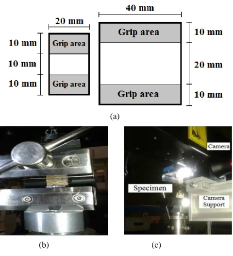
Figure 3.6. (a) X-ray tomography equipment and (b) coconut fiber sample...41
Figure 3.7. Preparation of coconut fibers prior to the in-situ tensile test: (a) fibers fixed on the paper, (b) fiber glued on paper, (c) cuts of the paper sides and (d) fibers inserted in the SEM...43
Figure 3.8. Tensile test on coconut fiber mats: (a) specimen dimensions and (b-c) apparatus coupled in tensile machine...45
Figure 3.9. (a) Apparatus for tensile test in virgin polypropylene and (b) surface prepared for DIC analysis. 1 pixel represents 52 m...46
Figure 3.10. Specimen texture used to determine damaged fields during uniaxial tensile testing...49
Figure 3.11. Use of extensometer to measure the stiffness modification during load/unload tensile testing...50
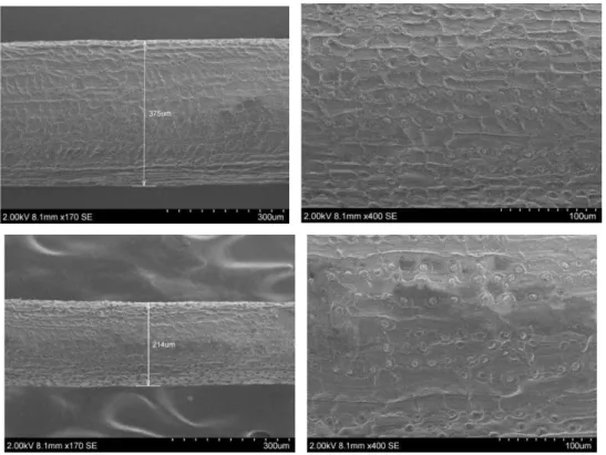
Figure 4.1. External surface of coconut fibers in 'as received' condition...52
Figure 4.2. External surface of dried coconut fibers...53
Figure 4.3. External surface of coconut fibers chemically treated...54
Figure 4.4. External surface of coconut fibers chemically treated and dried...55
Figure 4.5. Microcracks on a sample of a fiber chemically treated and dried...56
Figure 4.6. Diameter measurements along the fibers length in the conditions: (a) 'as received', (b) dried, (c) chemically treated and (d) chemically treated and dried...56
Figure 4.7. Statistical information on coconut fibers diameters: (a) standard deviation of diameters variation and (b) frequency of the measured values...58
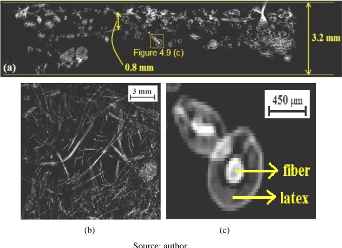
Figure 4.8. X-ray tomography observations of (a) transverse and (b-e) longitudinal sections along the inside of coconut fiber...59
Figure 4.9. X-ray tomography observations of coconut fiber mat: (a) lateral and (b) frontal views and (c) fiber involved by latex...60
Figure 4.10. (a) Cross-section of coconut fiber by tomography, (b) images in four gray levels, (c) quantity of pixels for each gray level and (d) surface fraction of the gray levels...61
Figure 4.11. (a) Longitudinal section of coconut fiber by tomography, (b) images in four gray levels, (c) quantity of pixels for each gray level and (d) surface fraction of the gray levels....62
Figure 4.12. Determination of total and effective areas of transverse section of coconut fiber by ImageJ software: (a) contour line and (b) variation of effective area along the length...64
Figure 4.13. Effective area of coconut fiber mat: (a) slice from TXT and (b) digital image....65
Figure 5.4. Elastic region: (a) mean longitudinal strains measured by tensile machine and by
CorreliQ4, (b) mean strains by CorreliQ4 and (c) Poisson's ratio...90
Figure 5.5. Monitoring the mechanical behavior of polypropylene in different regions: (a) deformed material, (b) all specimen analyzed, (c) necked region, (d) unecked region, (e) engineering stress-strain, (f) true stress-strain, (g) longitudinal and (h) transverse strains during the test...92
Figure 6.1. X-ray tomography and 3D-reconstruction on (a) PP-1L, (b) PP-2L, (c) RPP-1L and (d) RPP-2L...96
Figure 6.2. Coconut fibers partially involved by polymer...98
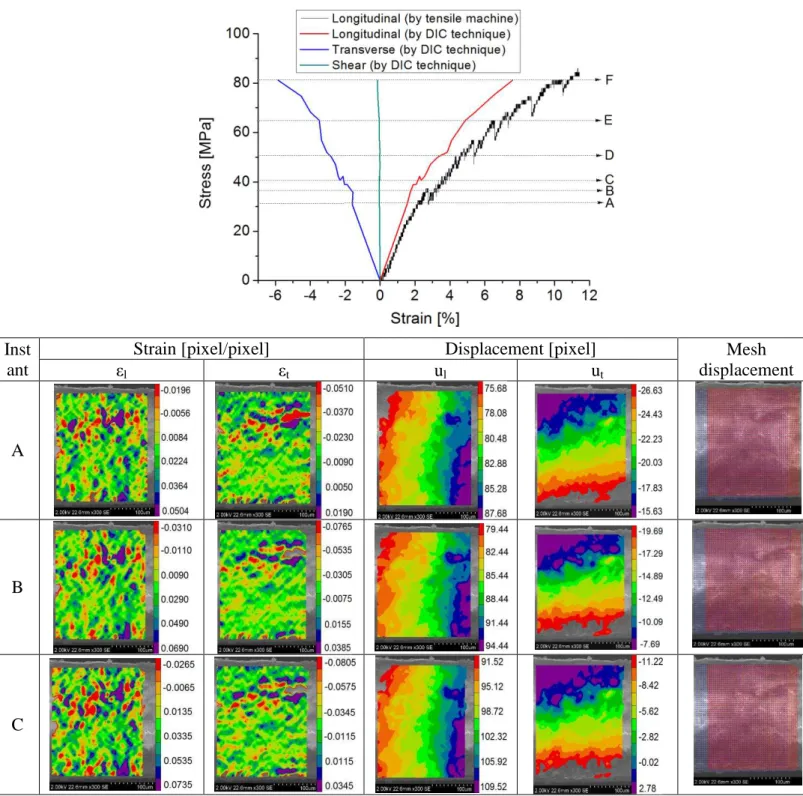
Figure 6.3. Tensile test followed by DIC and DIT on a RPP-1L: (a) stress x longitudinal strain curve, (b) stress x shear strain curve, (c) material rupture, (d) instant A (5.09 MPa; 0.38 %; 2.3 s), (e) instant B (10.09 MPa; 0.72 %; 4.4 s), (f) instant C (17.51 MPa; 1.60 %; 9.7 s), (g) instant D (22.35 MPa; 4.09 %; 25.0 s) e (h) instant E (19.76 MPa; 6.75 %; 41.1 s)...99
Figure 6.4. (a) Longitudinal and transverse strains measured by DIC and (b) Poisson's ratio on RPP-1L...102
Figure 6.5. Damage evolution x equivalent strain curve on RPP-1L...102
Figure 6.6. Stress-strain curves on PP-1L, PP-2L, RPP, RPP-1L and RPP-2L...103
Figure 6.7. Influence of PP recycling and coconut fiber addition on: (a) tensile strength, (b) modulus of elasticity and (c) strain at break...105
Figure 6.8. Rupture micrographs in composites...108
Figure 6.9. Microcracks on coconut fiber...110
Figure 7.1. Experimental and modeling measurements in stress-strain curves on coconut fiber...111
Figure 7.2. Relation of parameters obtained by the numerical model and the diameter of coconut fiber...112
Figure 7.3. Experimental and modeling measurements in stress-strain curves on PP...113
Figure 7.4. Experimental and modeling measurements in stress-strain curves on PP-1L...114
Figure 7.5. Experimental and modeling measurements in stress-strain curves on PP-2L...115
Figure 7.6. Experimental and modeling measurements in stress-strain curves on RPP...116
Figure 7.7. Experimental and modeling measurements in stress-strain curves on RPP-1L...117
Figure 7.8. Experimental and modeling measurements in stress-strain curves on RPP-2L...118
Figure 7.9. Stress-strain curves obtained by the numerical model...120
Figure 8.2. Crack propagation in composite manufactured with PP and RPP during tensile testing: (a) composite PP-1L in maximum stress (30.63 s) and (b) during the rupture stress (34.13 s), resulting in 3.5 s crack propagation. (c) Composite RPP-1L during maximum stress (25.02 s) and (d) during the rupture stress (41.14 s), resulting in 16.12 s crack propagation...126 Figure 8.3. Damage evolution on untreated coconut fiber (Ø = 280µm) using strain fields from DIC (ɛp = 0.4 x [1, 2, 4, 8, 16]; Cp = [-10, 12936, 20376, 24373, 26446]ν = 0.780)....128
Figure 8.4. Damage evolution on PP using strain fields from DIC (ɛp = 0.4 x [1, 2, 4, 8, 16];
Cp = [-1, λ02.5, 1513.4, 1868.7, 2060.2]ν = 0.377)...129
Figure 8.5. Damage evolution on PP-1L using strain fields from DIC (ɛp = 0.4 x [1, 2, 4, 8,
16]; Cp = [-1, 556.8, 875.7, 1046.6, 1135.1]ν = 0.2λ2)...129
Figure 8.6. Damage evolution on PP-2L using strain fields from DIC (ɛp = 0.4 x [1, 2, 4, 8,
16]; Cp = [-1, 240.1, 372.1, 441.4, 476.λ]ν = 0.31λ)...130
Figure 8.7. Damage evolution on RPP using strain fields from DIC (ɛp = 0.4 x [1, 2, 4, 8, 16];
Cp = [-1, 503.2, 7λ1.λ, λ46.8, 1027.1]ν = 0.3317)...131
Figure 8.8. Damage evolution on RPP-1L using strain fields from DIC (ɛp = 0.4 x [1, 2, 4, 8,
16]; Cp = [-1, 82.0, 127.6, 151.7, 164.1]ν = 0.3333)...131
Figure 8.9. Damage evolution on RPP-2L using strain fields from DIC (ɛp = 0.4 x [1, 2, 4, 8,
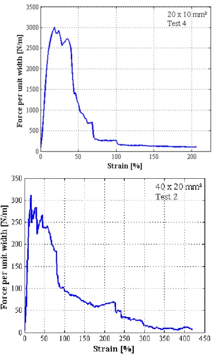
16]ν = 0.3213)...132 Figure 8.10. Comparison between measured and reconstructed displacements (expressed in pixels), and corresponding differences for the last instant on (a) coconut fiber, (b) PP, (c) PP-1L, (d) PP-2L, (e) RPP, (f) RPP-1L and (g) RPP-2L...133 Figure 8.11. Rupture observations on PP-2L by DIC during load/unload tensile testing: (a) 33.12 s; 5.17 MPa; 0.004 pix/pix (second cycle of loading; average engineering longitudinal strain) (b) 140.49 s; 26.19 MPa; 0.05246 pix/pix (engineering longitudinal strain) and (c) 140.99 s...136 Figure 8.12. (a) Engineering and true stress-strain curves on PP-2L and (b) engineering and true damage measurements during load/unload tensile testing...137 Figure 8.13. Loading/unloading cycles and damage evolution on PP, PP-1L, PP-2L, RPP, RPP-1L and RPP-2L through engineering stress-strain curves...137
Tables
Table 2.2. Physical and mechanical properties of natural fibers compared with traditional
fibers...15
Table 3.1. Experimental measurements of grammage of coconut fiber mat...35
Table 3.2. Summary of characterizations employed in this work...51
Table 4.1. Average and standard deviations of the coconut fiber diameters measurements....58
Table 4.2. Influence of displacement rate on mechanical properties of untreated coconut fibers for a distance of 15 mm between the grips...70
Table 7.1. Material parameters using numerical modeling...119
Table 8.1. Critical damage from experimental stress-strain curves...125
Simbols and abbreviations
Simbols : force : versor
σ: nominal stress : effective stress
: true stress
u: ultimate stress
σsd: standard deviation
σR: tensile strength u: systematic error
S: total area So: area of defects : area without defects
Ao: area of the initial cross-section
l: lenght w: width t: thickness
D: damage variable : diameter
Dn : damage associated with a plane normal
Dc: critical damage
: strain
ɛt: transverse strain
ɛl: longitudinal strain
ɛw: strain in width
ɛt: strain in thickness
: effective linear deformation
: equivalent strain
ɛeng: engineering srain
upre : measured displacement
uest: deformation truly occurred
ul: longitudinal displacement
ut: transverse displacement
Ux: displacement filed in x axis Uy: displacement filed in y axis
Cp: amplitude identified in strain histograms
E: modulus of elasticity
: modulus of elasticity of a damaged material , μ δame coefficients of the virgin material
: Poisson's ratio
ρ: error or fluctuation value in damage measurement by strain fields
χ: ratio of the standard deviation
a,b: characteristic parameters of the material n: number of samples
: wavelength of the radiation : power radiated
, : first and second radiations constants T: temperarature
: Stefan–Boltzmann’s constant
μ emissivity
Abbreviations
ASTM: American Society for Testing and Materials DIC: Digital Image Correlation
DIT: Digital Infrared Thermography DSC: Differential Scanning Calorimetry
ENS-Cachan: École Normale Supérieure de Cachan HDPE: high density polyethylene)
LMT-Cachan: Laboratoire de Mécanique et Technologie of ENS-Cachan MFI: melt flow index
PC: polycarbonate
PEEK: poly (éteréter ketone) PET (polyethylene terephthalate) PP: polypropylene
PPS: poly (phenylene sulfide) PS: polystyrene
PVC: polyvinyl chloride RPP: recycled polypropylene
1. Introduction
__________________________________________________________________________________________
1.
Introduction
1.1. Overall considerations
The issues related to environmental impact and sustainable development has encouraged to interest in materials from natural sources, as well as they stimulate the development of new raw materials and products (George et al., 2001). The decreasing of global petroleum resources, along with an awareness of global environmental problems, such as a lack of landfills, has promoted the development of alternative materials, such as polymers and composites from natural sources. These newly developed materials are in agreement with the environmental concerns and its development is free of the non-renewable petroleum resources (Zulkifli et al., 2015).
In this sense, recycled, renewable and reusable materials have preference front of virgin materials, which require more energy and emit more CO2 during its manufacturing. The
recycling of plastic waste and the use of coconut husks, for example, as engineering materials corroborate with this environmental context.
Numerous vegetable fibers, such as green coconut fibers, are usually discarded. They are inside the coconut husks which are often discarded on Brazilian beaches after consumption of its water. This material disposal is significant in waste and landfills of the Brazilian great coastal cities. Its reutilization may provide the manufacturing of materials for industrial and civil sector in order to meet these current requirements. Moreover, Brazil has great potential to produce and market different vegetable fibers, due to their variety and abundance of its biomass (Razera, 2006).
In this context, these vegetable fibers have been investigated to be used as reinforcement in composite polymer matrices, because they combine important properties and are in agreement with sustainable project ideas. Furthermore, the coconut fibers present strong ecological appeal and characteristics such as low cost, low density, renewability, biodegradability, non-toxic and low abrasive, attractive thermal and acoustic properties (Bledzki & Gassan, 1999).
1. Introduction
__________________________________________________________________________________________
fibers for the manufacture of materials in which the mechanical resistance is not the most important requirement (Defoirdt et al., 2010).
Compared to glass-fibers, the production of natural fibers causes less environmental impacts. This is because the cultivation of natural fibers depends primarily on solar energy and needs small amount of energy from fossil fuels in the production and extraction processes (Joshia et al., 2004).
However, there are some disadvantages in using natural fibers as reinforcement in composite materials, such as: quality and production efficiency, which depend on the natural conditions; heterogeneity of their properties which may be associated with the sazonality, production, extraction and processing conditions of the fibers, and the hydrophilic behavior which leads to water absorption in the composite systems, as well as poor compatibility with polymers (Tomczak, 2010).
A German company continually invests in the development of these materials, aiming, among other things, concern for ecological issues, the price and availability of these materials in nature (The National Non-Food Crops Centre, 2006). A vehicle of this German manufacturer, for example, uses 24 kg of renewable materials, of which more than 13 kg represent vegetable fibers (Figure 1.1). These materials are used in coatings doors and other internal parts of the vehicle.
Figure 1.1. Vehicle from a German company and vegetable fibers.
Source: The National Non-Food Crops Centre, 2006.
1. Introduction
__________________________________________________________________________________________
equipments and many others. PP possesses a number of preferable properties such as high thermal stability, low density and low cost. However, like other polymeric materials, the recycling of PP degrades its mechanical and thermal properties due to the high temperatures involved in the process. The inferior properties of recycled PP, compared to those of virgin PP, can be improved by incorporating synthetic or natural fibers (Zulkifli et al., 2015).
The use of coconut fiber with recycled polypropylene (RPP) to fabricate composites may be an advantageous alternative to reduce the cost of some products, combining the advantages of using vegetable fibers and reusing the polypropylene (PP).
The main problem encountered with cellulose reinforced polymer composites consists in the inherent incompatibility between the hydrophilic cellulose fibers and the hydrophobic PP matrix. Coupling agents, such as silanes, isocyanates, and graft copolymers of maleic anhydride, have been used in most natural fiber reinforced thermoplastics. Surface treatments on vegetable fiber also may be adopted. Their main roles is to improve the adhesion between the reinforcing fiber and the thermoplastic matrix.
Thus, the advantages and limitations technical of these composites fabricated by polypropylene matrix and coconut fibers need to be investigated in this work for identification of future commercial applications, aiming to increase its employability and commercial value. Some theories and experimental techniques on mechanical performance are required to provide knowledge about applications, durability and dynamic response of engineering materials. Thereby, numerical simulation and structural computations, as well as formulation of damage models and damage identification procedures were developed. In this work, some of these damage models and numerical simulation will be explored.
Damage mechanics is a topic of applied mechanics that relies on the continuum mechanics. Most of the studies about damage mechanics uses state variables to represent the effects of damage on the stiffness and remaining life of the material that is damaging as a result of thermomechanical load and ageing. A damage activation criterion is needed to predict damage initiation (Struik, 1978).
Kachanov (1958) was the first researcher that introduced the concept of damage. Nowadays, this concept reached a stage which allows various practical engineering applications. In contrast to fracture mechanics which considers the process of initiation and growth of micro-cracks as a discontinuous phenomenon, continuum damage mechanics uses a continuous variable which is related to the defects density.
1. Introduction
__________________________________________________________________________________________
choice between conventional techniques, as accuracy, simplicity and cost must be evaluated. Digital Image Correlation (DIC) is a technique which may prove to be ideally suited for the study of crack propagation and material deformation in real-world applications (McCormick & Lord, 2010).
Strain-field analysis via DIC also referred as photogrammetry is a powerful tool, which can be applied to map lateral strain distributions at different length scales. It allows a detailed investigation of complex micromechanical questions that are associated with the lateral distribution of the strain in heterogeneous materials (Godara et al., 2009). DIC technique is simple to use and cost effective compared to other techniques such as speckle interferometery, and more accurate and subjective than manual measurement methods, leading to a huge range of potential applications (McCormick & Lord, 2010).
Digital Infrared Thermography (DIT) is also strong tool for damage and failure identifications. DIT analysis one of the nondestructive inspection techniques to detect delaminations in composite and polymeric materials. These defects are identified by capturing the temperature gradient of material surfaces. In order for this technique to be effective in damage detection, DIT inspections should be conducted at certain time windows with favorable temperature conditions to get clear temperature gradients on inspected surfaces (Watase et al., 2015).
Apart from its use as non-destructive evaluation technique, infrared thermography is also employed to record a video during the impact event. The visualization of thermal signatures, caused by local dissipation of impact energy, allows gaining information which is useful for understanding the material response to mechanical loading. In particular, the two techniques allow for estimation, in a reliable way, of the overall delamination extension which is of utmost importance for material design purposes (Meola et al., 2015).
1.2. Objectives
1. Introduction
__________________________________________________________________________________________
strain fields in elastic and plastic regimes, as well as evaluating their temperature gradients during mechanical loading.
This study aims to investigate the effect of different treatment performed in green coconut fiber surfaces on morphological and mechanical properties.
This study also aims to formulate a numerical model describing the mechanical behavior of each material and formulate constitutive equations describing the materials degradation.
1.3. Thesis structure
Chapter 2 presents a literature review on the materials studied, with emphasis on polymer composites, polypropylene, polypropylene recycling, natural fibers, fiber-matrix interface and damage demonstrations in composite materials. This chapter concludes presenting the theory of continuum damage mechanics, with emphasis on the damage evolution by modification of stiffness in load/unload test and by damaged regions accompanied by images.
Chapter 3 presents the conditions for obtaining and manufacturing of these materials. Then, experimental procedures and equipment according to standards used will be described in order to obtain their morphological and mechanical behavior. Then, Chapter 3 will approach about a numerical model that aims to predict their stress-strain curves. Finally, this chapter describes three approaches used to describe the evolution of damage of these materials: from numerical model parameters, from images of deformed material and from stiffness modification during loading/unloading test. The fundamental concepts and calibration procedures of two monitoring techniques for mechanical tests used in this study will be described in Appendix: Digital Image Correlation (DIC) and Digital Infrared Thermography (DIT).
1. Introduction
__________________________________________________________________________________________
Chapter 7 describes the experimental results of the tensile test using a numerical model based on mathematical expressions of hyperbolic tangents governed by parameters that describe the elastic and plastic regions of the stress-strain curves.
2. Literature review
__________________________________________________________________________________
2. Literature review
This chapter presents a bibliographic review on the materials used in this study: fiber-reinforced composites manufactured by thermoplastic polymer, coconut fiber, virgin and recycled polypropylene. An emphasis will be given on the concepts of recycling effects in polypropylene, and deformation mechanisms during uniaxial loading, as well as the fiber-matrix interface.
This chapter presents also some theories on damage mechanics which will be applied on the materials of this work.
2.1. Polymeric composites
The addition of non-reinforcing fillers is an ancient practice in the plastics industry with the cost reduction as main objective (Rabello, 2000). The possibility of modifications in material properties with the addition of fillers in appropriate concentrations resulted in a new vision of techniques of manufacturing and consequently some classes of materials may be developed. The polymeric composites may belong to this category and are defined as systems composed by combining two or more components containing significant proportions of them, where the mechanical and performance properties are sometimes expected to be superior to the individual constituents.
Polymeric composites are constituted by polymer matrix and dispersed filler which generally works as reinforcement. The matrix is a continuous phase which supports and protects the reinforcement, transferring the mechanical loading to the fiber. The dispersed phase is distributed in the matrix and is typically more rigid and resistant than matrix. The reinforcements may be found in different shapes: particulate or lamellar or in the form of short or long fibers (continuous or discontinuous).
2. Literature review
__________________________________________________________________________________
is a minimum critical length for the reinforcement in polymer matrix that results in optimum mechanical performances.
The morphology variation of the natural fibers, when used as reinforcement, is responsible for influencing the tensile strength and toughness of composites. Other factors, such as fiber-matrix interface and fiber orientation, are crucial to predict and characterize their mechanical properties. For example, the tensile strength of composites reinforced by discontinuous fibers is lesser than composites reinforced by continuous fibers, when the same constituents and orientation are found in these materials (Zárate, 2000).
The most common arrangements of fibers in fiber-reinforced composite are: (a) continuous and aligned, (b) discontinuous and aligned, (c) discontinuous and randomly oriented, (d) two-directional and (e) three-dimensional fabrics, according to the scheme shown in Figure 2.1 (Matthews & Rawlings, 1994; Saeed et al., 2015).
Figure 2.1. Some fiber distributions in fiber-reinforced composites: (a) continuous and aligned, (b) discontinuous and aligned, (c) discontinuous and randomly oriented, (d)
two-directional and (e) three-dimensional fabrics.
Source: (a-d) Matthews & Rawlings, 1994; (e) Saeed et al., 2015.
2. Literature review
__________________________________________________________________________________
Currently, several studies of polymer composites are found in the literature in order to evaluate the mechanical, morphological and thermal properties through various processing possibilities, different types of matrices and reinforcements.
2.1.1. Polypropylene
Currently, the consumption of thermoplastic composites has increased in relation to thermoset composites due to the possibility of recycling of the thermoplastic polymers, thereby contributing to materials development in a sustainable manner. This utilization is also related to the development of thermoplastics with attractive physical and mechanical properties such as PP, poly (éteréter ketone) (PEEK), poly (phenylene sulfide) (PPS) and polycarbonate (PC). The polypropylene was first polymerized in 1955 by Natta and has been recognized as a polymeric material with a wide variety of uses due its design versatility at the molecular level with an attractive cost (Hamada et al., 2000).
Thermoplastic resins have long molecules with a length of about 20 to 30 nm and flow easily under mechanical loading at moderate temperatures, thus allowing be manufactured in desired shape while maintaining the same shape when cooled to room temperature (Davis et al., 1982). These polymers can be repeatedly heated, manufactured and cooled, thus, more easily recycled. The combination of low density, chemical resistance, low cost and a balance between stiffness and toughness allows thermoplastics materials to occupy the space of other materials in many important applications (Elmajdoubi & Vu-Khanh, 2003).
The polypropylene (PP) is a thermoplastic obtained by polymerization of propylene
monomer (C3H6) through of polyaddition reaction process. This semicrystalline polymer has
an approximate density of 0.90 to 0.91 g/cm3. Its glass transition temperature and melting temperature are approximately -18°C and 165°C, respectively. Its mechanical strength and hardness are relatively attractive because its crystallinity is situated between 60 and 70%. The modulus of elasticity, tensile strength, yield strength and ultimate elongation of PP are approximately 1.14 to 1.55 GPa, 31.0 to 41.4 MPa, 31.0 to 37.2 MPa and 100 to 600%, respectively (Santos, 2006).
2. Literature review
__________________________________________________________________________________
crystallization of the material may be attributed to post-crystallization phenomenon. The PP semicrystalline regions are bonded by amorphous regions and strongly influence the mechanical properties (Fiebig et al., 1999).
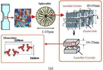
Semicrystalline polymers contain amorphous and ordered crystalline phases. When solidified from the pure melt, these polymers show a spherulitic structure in which crystalline lamellae composed of folded chain crystallites radiate from the center of the spherulite in such a way that a constant long period or crystallinity is approximately maintained. The amorphous regions reside in the interlamellar regions in the form of tie chains, whose ends are attached to adjacent lamellae; loop chains, whose ends are attached to the same lamella; cilia chains with only one end attached to a lamella (or dangling chain ends), and floating chains which are not attached to any lamellae. This hierarchical structure is illustrated in Figure 2.2 (a).
A sequence of deformation events leads to different forms of plastic deformation in polypropylene, which are not only of scientific interest, but also of engineering relevance (Galeski, 2003; Pawlak & Galeski, 2005, 2008; Friedrich, 1983; Narisawa, 1980). The initial stages of tensile deformation are governed by the straining of molecular chains of the interlamellar amorphous phase (Figure 2.2 (b)), twinning, twist, interlamellar shear, rotation of lamellae stacks and lamellae separation (Nitta & Yamana, 2012; Pawlak & Galeski, 2008).
Figure 2.2. Structure and deformation observations in polypropylene: (a) molecular structure in different dimensions. (b) modifications in polymeric bonds during mechanical
loading, (c) stress-strain curve.
2. Literature review
__________________________________________________________________________________
(b) (c) Source:Nitta & Yamana, 2012.
Above Tg, the initial deformation is located in the amorphous regions because of its low modulus. The tensile deformation of a spherulite is inhomogeneous because the amorphous regions and the radially oriented lamellae have different angles to the direction of the tensile force. The main mode of plastic deformation of the amorphous components is believed to be interlamellar sliding, or lamellae separation in the equatorial regions, where the lamellae are oriented perpendicularly to the loading direction (Figure 2.2 (c)). The mobility of amorphous chains may vary locally (Struik, 1987). The constraints imposed by the lamellae imply that only a limited amount of deformation can be accommodated by the interlamellar amorphous phase (Bartczak, 1996). When this limit is reached, further deformation can proceed either by cavitation of the amorphous phase or by plastic deformation of crystals. Polypropylene shows a transition in the temperature region around 80°C, which is associated with mobility in the crystalline phase. When drawing is performed at elevated temperatures approaching this transition region, a change of the dominating deformation from cavitation towards shear yielding can be expected.
2. Literature review
__________________________________________________________________________________
2.1.2. Recycling of polypropylene
The nature and amount of different types of polymers in a given geographic area depend on the local consumer and industrial use. In addition, variations in these consumption indicators can have a high economic impact on the recycling industries and their investments (Strapasson, 2004).
Typically, the plastics present in higher quantities include HDPE (high density polyethylene), LDPE (low density polyethylene), PP, PS (polystyrene) and PET (polyethylene terephthalate), and therefore the recycling efforts typically focus on these polymers, in isolated form, added, combined in blends or reinforced by fibers (Strapasson, 2004).
Products made from recycled materials have attractive cost and present moderate quality, therefore a better understanding of these materials is needed in order to find appropriate and useful applications to replace, partially or fully, the virgin polymer. Some studies were performed to simulate the cycles of reprocessing (potential of recycling by multiple extrusions) or reprocessing/utilization (method of recycling simulation) using an accelerated thermal-oxidative aging stage (Strapasson, 2004).
Aurrekoetxea et al. (2001) used the reprocessing method by injection to study the mechanical properties of recycled PP. The melt viscosity was reduced and the crystallinity was increased due to reprocessing. Moreover, the modulus of elasticity and yield stress increased with the reprocessing, while elongation at break and fracture toughness decreased.
Incarnato et al. (1999, 2003) studied the effect of three processing cycles to evaluate the crystallinity and morphology of the PP by viscosity measurements, chromatography, Differential Scanning Calorimetry (DSC) and Scanning Electron Microscopy (SEM). During the recycling of post-consumer plastics, thermal and mechanical stresses (particularly shear) and macromolecule ruptures were reported. Furthermore, in the research of La Mantia and Dintcheva (2003) was noted that the presence of fillers, such as CaCO3, increased the
viscosity of PP in its molten state.
2. Literature review
__________________________________________________________________________________
41%) after an extrusion cycle, remaining at this level for the last cycle. Multiple extrusions of this isolated material caused a reduction in elongation at break from 700 to 550% after 7 cycles. Another PP condition (added by phenolic antioxidant and HDPE) used by the same authors showed different results; the aging test showed no influence on the elongation even after 20 cycles; multiple extrusions of this material in isolation caused a slight reduction in elongation at break from 800 to 750% after 7 cycles. It was remarked that all results of elongation at break presented a large scattering, with more than 100% deviation.
2.1.3. Natural fibers
Natural resources play an important role in economic activities, contributing to economic and social development of rural areas and underdeveloped regions (Sanadi, 2004). Among these resources, the natural fibers stand out, mainly due to the wide variety of species and availability. These fibers can be mineral, animal and vegetable sources, the latter being
the most widely used in the manufacture of composite materials (Frank, 2005).They may be
used as reinforcements in the manufacture of polymer composites, mainly due to the properties that these materials present, with economic and environmental advantages (Sain & Panthapulakkal, 2004). Different fibers are able to act as reinforcement in plastics, such as jute, flax, sisal, hemp, wood, etc.
Since 1994, some cars from Mercedes-Benz in Brazil already have internal parts fabricated containing coconut fibers. Composites made with natural fibers and thermoplastic matrices are used by the automotive industry as coatings and internal parts in order to reduce consumption of oil reserves and facilitate the recycling of automobiles (Holbery & Houston, 2006).
The use of lignocellulosic fibers in polymer composites is due to several factors, including cost reduction and lower weight. The price of natural fibers is unstable, varying in accordance to the region and the methods to obtaining. In addition to the cost, the use of these fibers in the manufacture of composites presents advantages when they replace traditional fibers such as glass and carbon fibers (Bledski & Gassan, 1999; Satyanarayana et al., 2005). Its renewable nature, high availability and non-abrasive characteristic corroborates with the equipment maintenance and in the production of new materials with benefits to the environment, making natural fibers a great material to replace some traditional fibers.
2. Literature review
__________________________________________________________________________________
part of the plant that are extracted (Bledski & Gassan, 1999). Table 2.1 presents the chemical composition of natural fibers from Brazil (B) and other countries (O) determined by different studies (Satyanarayana et al. 2007).
Table 2.1. Chemical composition of some natural fibers.
Fibers Source Cellulose (%)
Hemicellulose
(%) Lignin (%)
Grays (%)
Extractives (%)
B 54.3 to
55.2 16.8 to 29.7 25.3 to 24.6 1.1 0.7 to 3.5
O 32 to 44 27 to 32 19 to 24 4.3
-Banana O 60 to 65 6 to 8 5 to 10 1.2
-B 60 22.1 15.9 1.0
-O 59 to 71 12 to 13 11.8 to 12.9 0.7 0.5 to 2
Ramie O 80 to 85 3 to 4 0.5 - 6.4
Piaçava B 31.6 - 48.4 -
-Curaua B 70.7 to
73.6 21.1 7.5 to 11.1 0.8 to 0.9 2.5 to 2.8
B 74 to 75.2 10 to 13.9 7.6 to 8 -
-O 60 to 67 10 to 15 8 to 12 0.14 to
0.9 1.7 to 6
B 43.4 to 53 14.7 38.3 to 40.7 - 3.5
O 43.7 <1 45 - 4.5
Jute Sugarcane
bagasse
Sisal
Coconut
Source: Satyanarayana et al. 2007.
As can be observed, the chemical composition of natural fibers is changeable. The main constituents of lignocellulosic fibers are cellulose, hemicellulose and lignin. Cellulose can be considered a linear polymer consisting of glucose beta 1,4-glycosidic bonds. The linear structure and organized cellulose allows the formation of crystalline regions, showing good properties, reflecting in the stiffness of natural fibers. Hemicellulose, other component present in significant quantities, has some repeating units composed of sugars, branched structure and inferior properties than cellulose. Lignin presents a complex structure, being an amorphous polymer constituted by aliphatic and aromatic groups and also has inferior mechanical properties than cellulose (Bledski & Gassan, 1999; John & Thomas, 2007).
In most natural fibers, the microfibrils are oriented in respect to the fiber axis, presenting a typical angle. The higher the amount of cellulose and the smaller the angle formed between the cellulose microfibrils in the fiber, the higher the values of the elasticity modulus for natural fibers (John & Thomas, 2007; Eichhorn & Baillie, 2001).
2. Literature review
__________________________________________________________________________________
availability and non-abrasive characteristic of natural fibers are attractive parameters for various applications. Table 2.2 shows the physical and mechanical properties of natural fibers in comparison to some conventional fibers used as reinforcement (Bledski & Gassan, 1999; Satyanarayana et al. 2007).
Table 2.2. Physical and mechanical properties of natural fibers compared with traditional fibers. Fiber Density (g/cm³) Microfibrillar angle (°) Elastic Modulus (GPa) Tensile strenght (MPa) Failure strain (%) Sugarcane
bagasse 0.45 to 0.49 - 27.1 222 1.1
Jute 1.45 7 to 17 27 to 32 400 to 800 1.5 to 1.8
Ramie 1.5 7.5 to 12 44 500 to 870 1.2
Piaçava - - 1.07 to 4.59 108 to 147 6.4 to 21.9
Curaua 0.92 18.8 30 to 80 1250 to 3000 4 to 5.6
Sisal 1.26 to 1.33 20 17 to 22 324 to 630 2 to 5.1 Coconut 1.25 to 1.50 30 to 51 2.5 to 6 95 to 220 13 to 51.4
Fiberglass 2.5 - 70 2000 to 3500 2.5
Aramide 1.4 - 63 to 67 3000 to 3150 1.4
Source: Bledski & Gassan, 1999; Satyanarayana et al. 2007.
Coconut fiber or coir is a versatile lignocellulosic fiber obtained from the coconut fruit (Cocos nucifera) which grows mainly in tropical countries (Frank, 2005). Brazil has a great potential in the production of these fibers, with an annual production of approximately 1.5 billion of fruit in a cultivation area superior than 270,000 hectares. The northern region of Brazil is an important area for this cultivation (Satyanarayana et al. 2007). These fibers can be used in various applications, generating environmentally correct products. Coconut fibers can be extracted from both the mature fruit, as a byproduct of its industrialization, as well as from the green fruit, which is widely consumed in the Brazilian coast. The structure of the coconut fruit can be seen in Figure 2.3 (Bledzki et al., 2010).
2. Literature review
__________________________________________________________________________________
Figure 2.3. Structure of the coconut fruit.
Source: Bledzki et al., 2010.
Tomczak et al. (2007) have characterized coconut fibers from northern of Brazil, and these fibers showed a lower density of defects in their cells and higher degree of crystallinity than fibers from other countries. In Brazil, companies such as Embrapa, Poematec and Amafibra manufacture artifacts made by coconut fibers (seating for car seats, mattresses, mats and pots for gardening utensils) (Embrapa, 2013; Poematec, 2007; Amafibra, 2007).
Thermal analysis in mats manufactured with coconut fibers and latex showed better stability and less emission of toxic gases than conventional polyurethane foams (Salazar, 2005). However, these fibers present limitations in terms of mechanical behavior. As for other natural lignocellulosic fibers, the use of coconut fibers in the preparation of polymeric composite materials is limited due the poor compatibility with polymeric matrices.
Results show that the mechanical performance of coconut fibers as reinforcement in plastics is poor and inferior to other natural fibers (Wambua et al., 2003). This lower performance can be related to the poor interface fiber-matrix, properties of the fibers (Tables 2.1 and 2.2), low content of cellulose and high lignin content in its composition, high angle formed between the microfibrils, large and variable diameter. On the other hand, the variable diameter and elliptical shape found in the cells of coconut fiber allows higher flexibility and resistance to contact with the water, improving the ability of molten polymer to maintain contact with the fiber (wettability) (Frank, 2005).
2. Literature review
__________________________________________________________________________________
According to Kasliwal & Jones (2005), the use of natural fibers in thermoplastic resins is usually beneficial due to their availability, renewal capacity and favorable degree of efficiency in terms of strength/weight. As a result of these factors, plastic composites reinforced with natural fibers have received attention in the modification of thermoplastic resins such as PP, HDPE and PVC (polyvinyl chloride). These composites are potentially applicable on floors, furniture components, doors and building systems using light structures and pallets for storage structures. Another potential application is the manufacture of automotive interior panels, due to the increase of stiffness on the thermoplastic resin provided by these fibers and to the increase of softening temperature.
Brahmakumar et al. (2005) investigated the coconut fibers as reinforcement to LDPE. Some unique properties make it attractive for using it as reinforcement in LDPE composites. Coconut fibers possess high failure strain of 15–40% and contain a thin continuous surface layer of an aliphatic compound, hereinafter referred as waxy layer that difficults the compatibility between fiber and matrix (Prasad et al., 1983). On the other hand, long-chain aliphatic molecules and compounds have been used as adhesion promoters in wood fiber-reinforced non-polar thermoplastic composites (Bledzki & Gassan, 1999). Coconut fiber may, therefore, be used for reinforcing polyethylene without any surface treatment or modification. High failure strain of the fiber, which provides a better strain compatibility between the fiber and the matrix, could also be advantageous in short-fiber filled polyethylene composites (Brahmakumar et al., 2005).
2.1.4. Fiber-matrix interface and alkali treatment of natural fibers
One of the most important parameters in composite materials with one or more solid phases is the interface between the reinforcement and the matrix. The interface is the region where contact between the components of the composite occurs. The interfacial region is primarily responsible for the transfer of mechanical stress from the matrix to reinforcement. Inadequate adhesion between the phases involved in the interface may cause the onset of failures, affecting the composites performance (Santos, 2006).
2. Literature review
__________________________________________________________________________________
The wettability of a surface by another depends on the surface energy and surface area of these contacts (Santos, 2006).
The components of natural fibers, mainly cellulose, provide a hydrophilic and polar character to natural fibers, resulting in a poor compatibility in the preparation of thermoplastic matrix composites with hydrophobic and nonpolar character. This incompatibility between natural fibers and polymeric matrices generates a poor fiber/matrix interface, as well as low resistance to moisture absorption (Bledski & Gassan, 1999). These characteristics reduce the potential of natural fibers as reinforcement in polymers. Some chemical and physical modifications in thermoplastics or surface treatments on natural fibers may improve this adhesion (Li et al. 2007).
Physical treatments act on the fiber surface, resulting in structural changes that influence the mechanical bond with the polymers. Physical and structural methods, such as treatment with electrical discharge (corona, plasma), heat treatment and production of woven fibers fabrics have been used (Bledski & Gassan, 1999). Composites containing 20% of wood fibers treated with plasma showed higher values of modulus of elasticity and tensile strength than composites made of untreated fibers. In this case, chemical changes occur on the surface of the fibers due to an increase in aldehyde groups (Yuan et al., 2004).
Chemical treatments act not only on the surface of the fibers as they can reach its internal layers. Several treatments are described, such as alkali treatment, treatment with isocyanates, acetylation, etc. (Li et al. 2007 and George et al., 2001).
The fiber treatment with NaOH is also called mercerizing and is widely used as a pretreatment or coating of natural fibers. In these systems, there is a rupture of the hydrogen bonds that unite cellulose chains, giving a rougher surface that helps the mechanical anchoring.
The increase in the percentage crystallinity index of alkali treated fibers occurs because of the removal on the cementing materials, which leads to a better packing of cellulose chains (Varma et al., 1984). Additionally, treatment with NaOH leads to a decrease in the spiral angle, i.e. closer to fiber axis, and increase in molecular orientation. A fair amount of randomness is introduced in the orientation of the crystallites due to the removal of non-cellulosic matter (Sreenivasan et al., 1996). The modulus of elasticity of fibers, for example, is expected to increase with increasing degree of molecular orientation.
2. Literature review
__________________________________________________________________________________
of the cellulose microfibrils (Pickering, 2007). Well oriented cellulosic fibers such as flax have much higher Young's modulus than fibers with medium orientation, such as cotton. In addition to the modification of orientation and the consolidation of weak points, other important factors with regard to the mechanical properties after NaOH treatment could be the crystallite length and degree of crystallinity as well as the removal of fractions of cellulose at a very low degree of polymerization.
A widely used method to match composites prepared with natural fibers is the introduction of coupling agents. These systems differ in structure because it acts as a binder on the surfaces of the fibers and the matrix (Li et al. 2007; George et al., 2001). The use of coupling agents allows higher adherence at the interface of these systems, which results in changes on the final properties. Coupling agents have two functions, one able to react with the polar groups present in natural fibers, and one that promotes interaction with the polymer matrix. Several mechanisms describe the action of these agents in the fiber-matrix interface. The introduction of a coupling agent promotes the formation of resilient and flexible layers, forming an interfacial region that can present moderate values of modules among filler and matrix (Bledski & Gassan, 1999). The improvement in the wettability of the fiber-matrix is a result of the establishment of chemical bonds and acid-base effects between the fiber and the matrix (Sanadi et al., 1995).
2.2. Failure and damage mechanisms in polymeric and composite materials
The damage mechanisms start at plastic micro deformations. The plastic or damaged region in a polymeric material results from the breaking of bonds that composes the molecular chains, intrinsic discontinuities, residual stresses, the formation and propagation of "crazes" (Bueno, 2008).
Polymers do not contain crystallographic planes, dislocations, and grain boundaries; rather, they consist of long molecular chains. Fracture in these materials occurs in the atomic level and involves breaking bonds. A complicating feature for polymers, however, is that two types of bond govern the mechanical response: the covalent bonds between carbon atoms and the secondary van der Waals forces between molecule segments. Ultimate fracture normally requires breaking the latter, but the secondary bonds play a major role in the deformation mechanisms that lead to fracture (Anderson, 2005).
2. Literature review
__________________________________________________________________________________
temperatures (relative to Tg) polymers tend to be brittle, because there is insufficient time for the material to respond to stress with large-scale viscoelastic deformation or yielding. Highly cross-linked polymers are also incapable of large-scale viscoelastic deformation. The mechanism illustrated in Figure 2.4 (a), where molecular chains overcome van der Waals forces, does not apply to cross-linked polymers; primary bonds between chain segments must be broken for these materials to deform (Anderson, 2005).
Glassy polymers subject to tensile loading often yield by crazing, which is a highly localized deformation that leads to cavitation (void formation) and strains on the order of 100% (Bucknall, 1977). On the macroscopic level, crazing appears as a stress-whitened region, due to a low refractive index. The craze zone usually forms perpendicular to the maximum principal normal stress. Figure 2.4 (a) illustrates the mechanism for crazing in homogeneous glassy polymers. At sufficiently high strains, molecular chains form aligned packets called fibrils. Microvoids are formed between the fibrils. The aligned structure enables the fibrils to carry very high stresses relative to the undeformed amorphous state because covalent bonds are much stronger and stiffer than the secondary bonds. The fibrils elongate by incorporating additional material (Figure 2.4 (a)). Figure 2.4 (b) shows a fractograph of a craze zone (Anderson, 2005; Cayard, 1990).
Figure 2.4. (a) Craze formation in glassy polymers. Voids form between fibrils, which are bundles of aligned molecular chains. The craze zone grows by drawing additional material
into the fibrils. (b) Craze zone in polypropylene.
2. Literature review
__________________________________________________________________________________
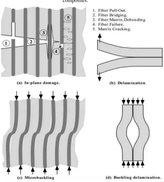
Many have attempted to apply fracture mechanics to fiber-reinforced composites, and have met with mixed success. Conventional fracture mechanics methodology assumes a single dominant crack that grows in a self-similar aspect, i.e., the crack increases in size (either through stable or unstable growth), but its shape and orientation remain the same. Fracture of a fiber-reinforced composite, however, is often controlled by numerous microcracks distributed throughout the material, rather than a single macroscopic crack. There are situations where fracture mechanics is appropriate for composites, but it is important to recognize the limitations of theories that were intended for homogeneous materials (Anderson, 2005).
2. Literature review
__________________________________________________________________________________
Figure 2.5. Examples of damage and fracture mechanisms in fiber-reinforced composites.
Source: Anderson, 2005.
2.3. Damage mechanics
2. Literature review
__________________________________________________________________________________
Elements of damage mechanics
A defect within the microstructure of a solid is presented in the Figure 2.6. A Representative Volume Element (RVE) must be large enough to be considered that the distribution of defects in its interior is homogeneous. Furthermore, it is assumed that this element has no local high gradients quantities of discontinuity, such as deformation. Thus, a continuum material will be assumed for the representative functions of the occurring phenomena in an element and their properties will be considered in terms of average values associated to any material point.
Figure 2.6. Representative volume element of a damaged material.
Source: Lemaitre, 1984.
Definition of effective stress
A situation where a mechanical loading on the Representative Volume section is
considered according to previous section, where a force is applied to the opposite faces and
oriented by versor (Figure 4.8); a total area S of section normal inside of the element is also adopted. Under these conditions, σ = F/S is the nominal stress at any point on generic section. Assuming that the number of defects is totally unable to transfer stress, it is possible to define an effective stress by taking in consideration only an intact part of the section. Considering as the area with no defects (area which effectively resists to mechanical loading) of the S section. Then the area of defects (So) is:
2. Literature review
__________________________________________________________________________________
By definition, the damage Dn, in case associated with a plane normal , is defined by the relation (Lemaitre, 1984):
Dn =
(2.2)
Note that the damage variable takes values in the range 0 < Dn < 1, and Dn = 0 corresponds to the situation where the material has no damage (intact material) and Dn = 1 indicates a total state of deterioration. Thus, portion of the effectively resistant section can be expressed in terms of damage variable as:
= S
–
So = S (1
–
Dn)
(2.3)Thus, the nominal stress σ and effective are defined by:
=
and
=
(2.4)
Therefore, we have:
=
(2.5)
As the entire area is smaller than the nominal area, the effective stress in damage means results comparatively larger than nominal stress for the same force applied. In particular, note that:
= , for intact material;
→ ∞
, for completely damaged material.Note that, for the same point, the variable Dn can assume different values according to
2. Literature review
__________________________________________________________________________________
The damage scale corresponds to a situation in which the micro defects presented in the volume element are approximately distributed in an uniform manner, so that the measurement of damage is the same in any point or surface, ie, independent of the orientation of normal . In other words, a single value of the damage variable is sufficient to characterize completely the local state of deterioration, as follows:
D = Dn , (2.6)
Definition of effective strain
The effective stress concept is analogous to the effective strain and also is determined from the analysis of a uniaxial strain situation imposed on the volume element oriented at a certain direction defined by versor. Assuming Δl as a variation of the initial length lo due the effect of deformation imposed, the strain measurement is defined by the relation:
(2.7)
However, the length of a material will be increased during mechanical stress if the volume element presents initial defects or internal discontinuities (Figure 2.7). This increment or failure propagation may be represented by Δd. Thus, in the deformation process only the portion Δl - Δd can effectively be considered a deformation measurement of this material.
Figure 2.7. Increase in length due to the opening of defects.
2. Literature review
__________________________________________________________________________________
Therefore, the measure of effective linear deformation can be defined as:
(2.8)
Other definition for a damage variable can then be proposed:
(2.9)
Note that this definition is also associated with a certain direction . Taking in consideration the new variable of the damage, it follows that the measures of nominal and effective linear deformation are related by:
(2.10)
The two scalar damage variables introduced before (So and Δd) can be unified if one considers that the volume corresponding to the damaged part is the same in both cases. This consideration can be coherent, because the equilibrium of stress or the deformations compatibility is analyzed in a situation of uniaxial mechanical loading on the same volume. Thus, the damaged volume can be represented by:
Vd = SoΔl = S Δd (2.11)
Taking in consideration the previous relations it is easy to see that Dn = .
Constitutive relationship involving equivalence of deformation
2. Literature review
__________________________________________________________________________________
In context of a damage response in composite materials, this principle is based on the proposition that the material has continuous fibers arrangement with slightly different strengths from one another, which are submitted to the same deformation. Due to the different resistance of fibers, they start to break, initiating the damage process. Rearranging the previous equations, it is obtained:
or – D) E (2.12)
In this way, the secant modulus of elastic stiffness for a continuous materials of equivalent response to the damaged material is:
(2.13)
and damage variable can be identified by:
(2.14)
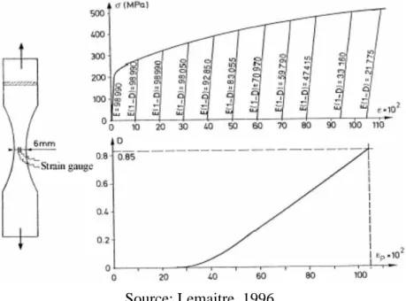
This method requires accurate measurements of deformation and strain gauges are usually
used for higher accuracy in the values obtained during the loading/unloading cycles. An example
is given in Figure 2.8 for a ductile damage on copper by large deformations, where is the true
stress:
t = (1 + ) (2.15)
Figure 2.8. Measurement of ductile damage on copper (99.9 %) at room temperature.
2. Literature review
__________________________________________________________________________________
Criterion failure: critical damage (Dc)
The definition of meso-scale rupture is given during the crack initiation or when the degradation process of the fiber-matrix interface represents all the surface of Representative Volume Element. In this case, therefore, D = 1. In many cases, this process is caused by an instability which leads to the rupture of atomic bonds. It corresponds to a critical value of
damage, Dc, which depends on the material and loading conditions.
The final separation of atoms is characterized by a critical value of the effective stress acting on an area resistance. This stress is called σ∞ because it is the maximum stress that could be applied in the material:
=
(2.16)
In practice, ∞ must be approximated by a ultimate stress u, thus we have:
Dc = 1 – (2.17)
These equations provide the critical value of damage during the initiation of a mesocrack occurring in a tensile testing σR. The ultimate strength σu may be identified for each material. Dc should range between Dc0 (for pure brittle fractures) and Dc1 (for pure ductile fractures), however Dc is usually about 0.2 to 0.5.
This relation is applied to a pure monotonic tensile test and is taken as a reference. Therefore, it is possible to define the critical damage D1c for each material as follows:
D1c = 1 – (2.18)
where σRis the tensile strength.
Measurement of damage fields