Numerical analysis of steel-iber-reinforced concrete
beams using damage mechanics
Análise numérica de vigas de concreto com ibras
de aço utilizando mecânica do dano
a Pontifícia Universidade Católica de Goías, Goiânia, GO, Brasil; b Universidade Federal de Goías, Goiânia, GO, Brasil.
Received: 23 May 2015 • Accepted: 28 Sep 2015 • Available Online 21 Mar 2016
Abstract
Resumo
This work deals with numerical modeling of the mechanical behavior of steel-iber-reinforced concrete beams using a constitutive model based on
damage mechanics. Initially, the formulation of the damage model is presented. The concrete is assumed to be an initial elastic isotropic medium presenting anisotropy, permanent strains, and bimodularity induced by damage evolution. In order to take into account the contribution of the
steel iber to the mechanical behavior of the media, a homogenization procedure is employed. Finally, numerical analyses of steel-iber-reinforced
concrete beams submitted to bending loading are performed in order to show the good performance of the model and its potential.
Keywords: damage mechanics, steel-iber-reinforced concrete beams, constitutive model, concrete.
O artigo trata de uma contribuição à modelagem numérica do comportamento mecânico de vigas de concreto armado reforçado com ibras de aço utilizando modelos constitutivos baseados na Mecânica do Dano. O mesmo apresenta a formulação de um modelo de Dano proposto que admite o concreto como material inicialmente isótropo e elástico, mas com a evolução do processo de daniicação, exibe deformações plásticas, anisotropia e bimodularidade induzidas pelo dano. A incorporação das ibras na modelagem é efetuada por meio de um procedimento de homo
-geneização. Por im, análises numéricas de vigas de concreto armado reforçado com ibras de aço sujeitas à lexão são realizadas com o objetivo
de avaliar a aplicabilidade da modelagem proposta.
Palavras-chave: mecânica do dano, vigas de concreto reforçado com ibras de aço, modelo constitutivo, concreto.
W. M. PEREIRA JUNIOR a
1. Introduction
Every mechanical system submitted to static, dynamic, or thermal
loads presents a response. However, complex analyses must be
performed to obtain the mechanical response because the me-chanical system is composed of several structural elements that
evidence diferent mechanical behaviors. Some studies have re
-ported the use of diferent constitutive models for analysis of me -chanical concrete systems, such as references [1], [2], and [3].
In the context of numerical theories used in computational mechan
-ics, Continuum Damage Mechanics (CDM) deserves a mention,
because it shows reliable numerical responses for mechanical
sys-tems composed of complex materials like concrete. An important
work was developed by La Borderie [4], who proposed a
homog-enization rule with a damage model for iber-reinforced concrete in order to obtain the updated stress in the composite matrix.
On the other hand, Li and Li [5] studied concrete damage models
applied to the analysis of tensioned ibers. In their work, the con -crete was treated as a medium that shows hardening behavior for increasing strain. The results are satisfactory when compared to
experimental ones. The same observation is valid for the work de
-veloped by Lee and Liang [6], who applied CDM to iber-reinforced
cellular concrete.
Moreover, Hameed et al. [7] used damage mechanics to model
steel-iber-reinforced concrete beams, obtaining satisfactory re
-sults when compared to experimental tests. Pasa [8] also evalu
-ated the mechanical behavior of steel-iber-reinforced concrete us
-ing the inite element method with smeared crack models.
According to Guello [9], the nonlinear behavior of the concrete,
which takes place even at low stress levels, is inluenced by nucle -ation and propag-ation of microcracks during the loading process. Thus, the importance of a reliable cracking model can be seen.
However, in the context of improved materials for structural appli
-cation, nowadays, steel-iber-reinforced concrete is largely used,
which reduces the tensile brittle behavior of concrete, leading to a
better strain capacity due to the clipping efect of the cracks pro
-vided by ibers.
According to reference [18], the efect of the addition of steel ibers on the lexural strength of concrete and mortar is more evident with
regard to the tensile behavior than the compression strength. This paper intends to present a proposal for modeling the mechanical
behavior of iber-reinforced concrete using the damage model pro
-posed by Pituba and Fernandes [3], which has already been tested
in conventional concrete structures. The one-dimensional version of this proposed modeling is presented and applied to the analysis
of iber-reinforced concrete beams in order to mark out a discus
-sion about the viability and employment restrictions in simpliied numerical analyses in the context of structural engineering.
2. Computational modeling
2.1 Modeling of reinforcement
In this paper, a one-dimensional model has been used to describe the mechanical behavior of reinforcement bars, which contribute
only to the axial strength of the structure. The reinforcement trans -versal section is transformed into a layer located according to its
center of gravity (see Figure 1). A bilinear elastoplastic model is
used to represent the tension and compression behavior of rein-forcement bars.
2.2 Damage model for concrete
In this paper, it can be assumed that the concrete belongs to the category of materials that can be considered as initially isotropic
and unimodular, showing diferent behaviors in tension and com -pression regimes. Also, transverse isotropic behavior is shown when the medium presents a damage process. Moreover, the
model respects the principle of energy equivalence between the damaged real medium and the equivalent continuum medium es
-tablished in the CDM and presented by Pituba and Fernandes [3]. The damage model proposed in [3] is briely described. Initially, for
dominant tension states, a damage tensor can be written as:
(1)
D
T= f1(D1, D4, D5)
(AÄA)+ 2 f2(D4, D5)
)]( )
[(AÄI+IÄA - AÄA
where f1(D1, D4, D5) = D1 – 2 f2(D4, D5) and f2(D4, D5) = 1 – (1-D4)
(1-D5).
The variable D1 represents the damage in the direction orthog -onal to the transverse isotropy local plane of the material, while
D4 is representative of the damage due to the sliding movement between the crack faces. The third damage variable, D5, is only
activated if a previous compression state accompanied by dam-age has occurred. The tensor I is the second-order identity tensor, and the tensor A is formed by the dyadic product of the unit vec-tor perpendicular to the transverse isotropy plane for itself. Those products are given in [3].
For dominant compression states, another damage tensor is
proposed:
(2)
DC
= f
1(D
2,D
4,D
5)
(AÄA)+f
2(D
3)
[(IÄI)-(AÄA)]+ 2f3(D4,D5)
[(AÄI+IÄA)-(AÄA)]where f1(D2, D4, D5) = D2 – 2 f3(D4, D5) ,f2(D3) = D3 and f3(D4, D5)=
1 – (1-D4) (1-D5).
Note that the compression damage tensor introduces two
addi-tional scalar variables in its composition: D2 and D3. The variable D2 (damage perpendicular to the transverse isotropy local plane) reduces the Young’s modulus in that direction and, in conjunction with D3 (which represents the damage in the transverse isotropy plane), degrades the Poisson’s ratio throughout the planes perpen -dicular to the transverse isotropy plane.
Finally, the constitutive tensor is written as:
(3)
=
T
E
l11[IÄI]+2m1[IÄI]- l
22+(
D
1,
D
4,
D
5)
[AÄA] )( 1 12+ D
- l
[A I+I A]
-
m
2(
D
4,
D
5)
[AÄI+IÄA](4)
=
C
E
l11[IÄI]+2m1[IÄI]-l
-22(
D
2,
D
3,
D
4,
D
5)
[AÄA]-l
12-(
D
2,
D
3)
[A I+I A]
)
(
3 11l
-D
-
[
I I
] –
0 113 0(12)
- n
l
-(D)
n
[
I
ÄI
]
-
m
2(
D
4,
D
5)
[AÄI+IÄA]where l11 = s0 and m1 = m0 . The remaining parameters will exist only for no-null damage, evidencing the anisotropy and bimodu-larity induced by the damage process. Those parameters are given by:
(5)
(6)
)]
1
)(
1
(
)
1
[(
)
,
(
2 3 0 3 2 2 312-
D
D
=
l
-
D
-
-
D
-
D
l
(7)
)
2
(
)
(
2 3 3 0 311-
D
=
l
D
-
D
l
;
]
)
1
(
)
1
(
1
[
2
)
,
(
2 5 2 4 0 5 42
D
D
= m
-
-
D
-
D
m
The constitutive model includes two damage tensors in order to take into account the bimodularity induced by damage in the
con-crete behavior. Therefore, a criterion deining the tension and com -pression dominant states is necessary to indicate what damage tensor should be used. Besides, there are two criteria dealing with
the beginning and evolution of the damage process. More details
can be found in Pituba and Fernandes [3].
The one-dimensional version of the damage model has been
im-plemented in a inite element code for bar structures analysis with inite layered elements in order to model the reinforced concrete framed structures (Figure 1). In the transversal section, a certain
layer can contain steel and concrete. A perfect adherence between
materials is adopted and an equivalent elasticity modulus and in
-elastic strain are deined for each layer by using the homogeniza -tion rule (see reference [3]).
The model proposed in reference [3] does not take into account plastic strains that arise when unloading situations take place. Thus, if plastic strains are not negligible, they should be consid-ered for reliable modeling in unloading situations.
In fact, the inelastic strains and damage occur simultaneously.
Ac-cording to La Borderie [4], microcracking and the existence of voids
in the material are responsible for those phenomena. The micro-voids are a cause of inelastic strains because they do not permit the full closure of microcracks in the unloading processes. On the other hand, the surfaces of the microcracks are irregular, and this is
another reason for the diiculty in achieving their total closure. Taking into account just the uniaxial cases, the formulation of the proposed model is then extended to incorporate permanent strains,
which are assumed to appear after the damage has been activated.
Assuming, for simplicity, that the permanent strains are exclusively
composed of volumetric strains, as has already been considered
in other work [11], and taking into account the unilateral efect, the
evolution law for the permanent strains is:
(8)
where gT and gC are inelastic potentials.
For simplicity, it is assumed that the plastic strains are exclusively composed of volumetric strains [12]. The potentials can be ex -pressed by:
(9)
(10)
where the damage functions bT (DT) and bC (DC) are material pa-rameters. In order to apply the damage model to concrete, the fol-lowing functions are adopted:
(12)
where
I
l is the irst invariant of the stress tensor. Therefore, Eq. 8 is given by:
(13)
Finally, the evolution law for plastic strains
e
P, taking into account
the unilateral efect, is:
(14)
Observe that
b
TT andb
CC are parameters that are directlyre-lated to the evolution of permanent strains induced by damage in tension and in compression, respectively. When these parameters are null, the constitutive model originally proposed in reference [3]
is recovered. It is important to note that uniaxial tests in tension
and compression with loading and unloading are necessary for the
identiication of parameters
b
TT andb
C.On the other hand, considering Direction 1 as the longitudinal di
-rection of the inite element, the formulation previously presented is simpliied and described as follows:
(15)
(16)
(17)
The complementary elastic energies of the damaged medium in ten-sion- and compresten-sion-dominant states, respectively, as well as the
variables associated with damage variables, are now expressed by:
(18)
(19)
(20)
(21)
(22)
More details can be found in Pituba and Fernandes [3]. Figure 1 shows the inite element used in this paper to perform the numeri -cal analyses.
2.3 Homogenization model for steel ibers
in concrete
The mechanical behavior of the steel-iber-reinforced concrete struc -tures submitted to loading and unloading processes depends on the
interaction between ibers and matrix. In this paper, the homogeniza -tion procedure proposed by La Borderie [4] is used. The constitutive
relationship of the steel-iber-reinforced concrete in the dominant ten
-sion regime is presented in Figure 2, which is obtained from the iber
pullout test. The following parameters can be obtained from this test: peak stress (spic), initial yield stress (ss), and ultimate strain (erupt).
Figur
e
ete
On the other hand, via the Voigt kinematic homogenization meth
-od, La Borderie [4] proposed the following expression for calculat
-ing the homogenized stress of the composite:
(23)
where:
CRFA
s
: homogenized stress;C
: volumetric fraction of the steel ibers; ms
: concrete matrix stress;f
s
: interfacial iber–matrix stress;It can be observed that a simplifying assumption has been
in-troduced: the strain of the iber and the matrix is considered the same. Furthermore, the random iber orientation is not taken into account in the proposed homogenization.
3. Numerical examples
3.1 Modeling of Velasco´s tests [13]
The irst numerical example deals with steel-iber-reinforced con -crete prisms submitted to a bending moment and tested by
Velas-co [13]. The steel ibers are named A to I in acVelas-cordance with NBR
15530:2007 [14]. Table 1 shows the main characteristics of the
steel ibers.
The concrete mixtures used in Velasco’s tests [14] were previously studied by Lopes [15]. MCWSF concrete matrix (see reference [13]) was chosen for the numerical modeling as well as steel-iber-reinforced concretes with iber contents of 1.0% (MCWSFA10), 1.5% (MCWSFA15), and 2.0% (MCWSFA20). Table 2 shows the characteristics of the concrete mixtures.
3.1.1 Parametric identiication of the Damage Model
Firstly, it is necessary obtain the values of the damage model pa
-rameters of the concrete matrix in order to model the behavior of the steel-iber-reinforced concrete. For this purpose, the MCWSF concrete matrix is taken (Table 2). These parameters were ob
-tained from the uniaxial compression and tension tests performed
by Velasco [13]. The stress–strain curve for tension was obtained from 100 × 100 × 400 mm prismatic specimens molded in the
hori-zontal direction, whereas the stress–strain curve for compression was obtained from tests on cylindrical specimens [19]. From an
inverse analysis of these tests, the values of the damage
param-eters for the concrete matrix were found and are listed in Table 3.
Soon after, these damage parameters were used to model 100 × 100 × 400 mm prismatic specimens with a span of 300 mm and
were submitted to bending moments. Nineteen inite elements with
ten layers each were used for modeling the prismatic specimen.
Table 1 – Features of the steel fibers used
by Velasco [13]
Analysed property Value
Specific weight (kg/m³) 7800
Length (mm) 35
Diameter (mm) 0.54
Aspect ratio (l/d) 65
Modulus of elasticity (GPa) 202 Tensile strength (MPa) 1342
Table 2 – Mechanical properties of concrete studied by Lopes [15]
Concrete Nomenclature fcm (MPa) Modulus of
elasticity (GPa) Poisson ratio (ν)
Fiber percentage (%)
1 MCWSF 55.1 35.7 0.17 0.00
2 MCWSFA10 61.7 34.8 0.19 1.00
3 MCWSFA15 70.0 37.4 0.19 1.50
4 MCWSFA20 72.4 37.7 0.21 2.00
Table 3 – Damage parameters identified for concrete
without fibers submitted to axial compression and tensile
Damage variable for compression Damage variable for tensile
A2 0.7 A1 15
B2 (Mpa
-1) 2.5 B
1 (Mpa
-1) 1200
YO2 (Mpa) 0.004945 YO1 (Mpa) 0.000086
The load–displacement curve in the middle of the span obtained
from the damage model was compared with result of the experi -mental test. This comparison showed that the numerical response
obtained from the damage model was not satisfactory and, for
this reason, new values for the damage model parameters in
ten-sion were determined (Table 4). A strong sensibility of the tenten-sion
Table 4 – Damage parameters and modulus of elasticity identified for concrete with 0.0% fibers from
four-point flexural test on prismatic specimens of 100 mm × 100 mm × 400 mm
Parameters Tensile Compression Fpico, num / Fpico, exp
E Mpa 41000 41000 0.0860%
A 15 0.7 0.0860%
B (Mpa-1) 1030 2.5 0.0860%
YO (Mpa) 0.00085 0.04945 0.0860%
B 0.00000045 0.0003 0.0860%
Table 5 – Model parameters of homogenization of La Borderie [4] for concrete with 1.0, 1.5, and 2.0%
steel fibers – Example I
Fiber volume Fpico, num (kN) Peak stress – spic
(MPa)
Yield stress – ss
(MPa)
Strain fracture – erupt
(m/m) Fpico, num / Fpico, exp
1.00% 38.20 530.00 477.00 0.0200 0.0460%
1.50% 58.00 570.00 513.00 0.0220 0.9600%
2.00% 62.80 460.00 414.00 0.0220 1.0800%
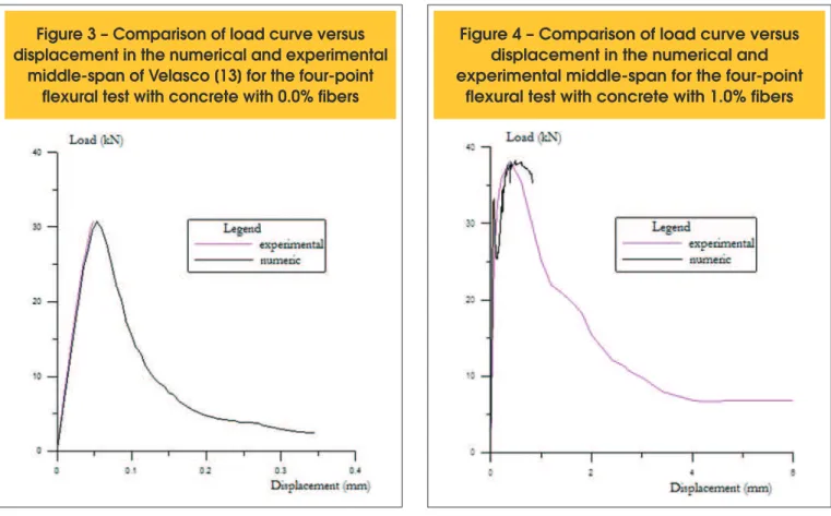
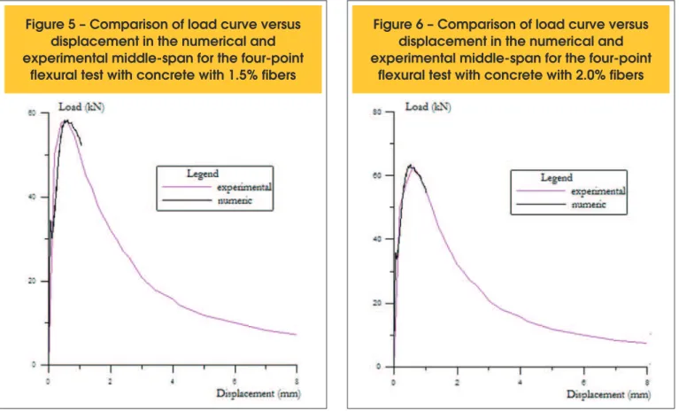
Figure 3 – Comparison of load curve versus
displacement in the numerical and experimental
middle-span of Velasco [13] for the four-point
flexural test with concrete with 0.0% fibers
Figure 4 – Comparison of load curve versus
displacement in the numerical and
experimental middle-span for the four-point
damage parameters was evidenced after convergence problems arose in peak loadings due to the high level of damage processes
in tensioned concrete layers. This evidences damage localization
processes in the middle of the span that the damage model is not
capable of describing. The inal result for the concrete without i
-bers is illustrated in Figure 3.
In sequence, the homogenization model parameters proposed by La Borderie [14] were obtained for the concrete with steel ibers.
An inverse analysis from prismatic specimens submitted to four bending points, with the same dimensions of the prismatic
speci-mens without ibers, was used for the parametric identiication of the SFRC [13]. The numerical and experimental responses are presented in Figures 4 to 6, where the numerical responses are considered satisfactory. The diference between numerical and experimental peak loads is smaller than 1%. The values of the ho
-mogenization model parameters are listed in Table 5. All analyses
related to damage processes are presented in Section 3.2.1.
3.1.2 Analyses of damage process
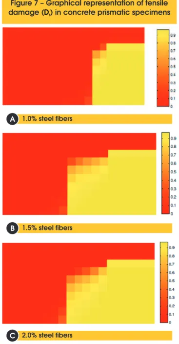
In order to analyze the damage distribution in the prismatic speci
-mens with steel-iber-reinforced concrete, the tension damage values near to peak loading are shown in Figure 7a. It can be ob -served that there is a high-level damage process at the bottom and middle span of the prism and a vanishing process of the damage is evidenced towards the support of the prism.
For the concrete with a steel iber content of 1.5%, the numerical mod -eling shows up to 1.05 mm of displacement at the middle of the span near to peak loading. The damage process in the prism is illustrated
in Figure 7b. For the concrete with a steel iber content of 2.0%, the damage distribution near to peak loading is shown in Figure 7c. Figure 8 and Table 6 show results of the efect of the steel iber in the system for a load level of 30 kN. From this igure and the table it is possible to note that the specimen with the highest iber content
showed lower damage at the same loading level, which evidences
the crack clipping by steel ibers, which leads to increased tensile
strength of the concrete specimen.
3.2 Modeling of Lopes´s tests [15]
The second numerical example deals with the analysis of a beam tested by Lopes [15]. Steel ibers A to I were used and their charac -teristics are given in Table 7. Table 8 shows the mechanical
prop-erties of the concrete used to make up the beam analyzed in this
section.
3.2.1 Parametric identiication of the damage model
The damage model parameters in tension for concrete without i -bers were obtained from inverse analysis of prismatic specimens
of 100 × 100 × 400 mm (Figure 9) with a span of 300 mm. These
specimens were submitted to four-point bending tests. On the other hand, the same parameters were adopted for compression
as for the previous numerical example (Table 9). The comparison between experimental and numerical responses is shown in ref
-erence [16]. A tolerance factor of 5% between experimental and
numerical peak loads was adopted. The elasticity modulus for the concrete obtained in tests was used here.
Figure 5 – Comparison of load curve versus
displacement in the numerical and
experimental middle-span for the four-point
flexural test with concrete with 1.5% fibers
Figure 6 – Comparison of load curve versus
displacement in the numerical and
experimental middle-span for the four-point
Soon after, the parameters of the homogenization model proposed by La Borderie [4] for concrete with 2% steel iber content were
determined by inverse analyses of the prismatic specimens tested by Lopes [15]. In this case, the damage model parameters for plain concrete were kept constant. Table 10 lists the values of the
ho-mogenization model parameters.
3.2.2 Modeling of beam test
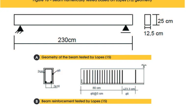
The geometry of the beam analyzed in this example, as well as the bar reinforcement detail, is shown in Figure 10. This beam was made of concrete with a steel iber content of 2% and was submit -ted to bending due to two loads applied at two points 100 cm apart from each other.
Due to beam symmetry, only half of the beam was modeled, using 50 inite elements. The cross-section was divided into 24 layers, as shown in Figure 11. The longitudinal reinforcement properties used
in the modeling are shown in Table 11. The parameters of the
dam-age model and the homogenization model are the same as those
shown in the previous item because the concrete of the beam is the same. Tables 9 and 10 list these parameters.
The comparison between numerical and experimental results is presented in Figure 12. A good approximation can be observed in
the initial loading, while there is a divergence between the curves for loading near to structural collapse. This behavior is due to frac-ture nucleation in the collapse regime, where the damage model
does not present an eicient response to damage localization.
Figure 7 – Graphical representation of tensile
damage ( ) in concrete prismatic specimens
D
t1.0% steel fibers
B
A
1.5% steel fibers
2.0% steel fibers
B
B
B
C
Figure 8 – Evolution of damage in the
1º tensileed layer in function of the percentage
of fibers in the load of 30 kN
Table 6 – Damage analyses for tension in
function of fiber percentage
Fiber percentage Damaged
element
Damage in the element
1.00% 19 0.2563
1.50% 19 0.1184
2.00% 19 0.1179
1,00E-02 1,00E-02 0
Table 7 – Steel fiber properties
used by Lopes [15]
Analysed property Value
Modulus of elasticity (GPa) 200 Tensile strength (MPa) 1150 Specific weight (kg/m³) 7850
Length (mm) 35
Diameter (mm) 0.55
Therefore, the analysis of this beam is limited to service loading,
which is deined in this paper as a loading lower than 40% of the
ultimate load.
This load level was chosen due to the fact that the Brazilian struc -tures are designed in the Ultimate Limit State [NBR 6118, 2014].
In the context of a normal combination of loadings, the loads are increased by a coeicient equal to 1.4 and the material’s strength is decreased by coeicients equal to 1.4 for concrete and 1.15 for
steel reinforcement. If the collapse load of the beam is divided by
the product of these coeicients in order to obtain the structural service loading, a value of 44% of the collapse load is obtained. This situation corresponds, approximately, to the rare combination for the Service Limit State established by the Brazilian Standards [NBR 6118, 2014]. A value of 40% of the collapse load was ad
-opted because in the service state only 40 to 70% of the live load is
acting on the structures. Then, the service load of the beam tested can be estimated as 68 kN, and a displacement of 3.297 mm in
the middle span was obtained from this load. The displacement obtained from the numerical simulation for this load was 2.695 mm,
which represents an error of 18% in the evaluation of the vertical
Table 8 – Mechanical properties of concrete obtained by Lopes [15] and used in numerical modeling
Concrete Nomenclature fcm (MPa) Modulus of
elasticity (GPa) Poisson ratio (u)
Fiber percentage (%)
1 F0V5SPrx1 59.06 34.91 0.20 0.00
2 FAb2V5SPg1 64.22 30.19 0.22 2.00
Figure 9 – Four-point flexure test used to identify the fiber variables
Table 9 – Damage parameters and elastic modulus of concrete without fibers identified from
the four-point flexural tests on prismatic specimens of 100 mm × 100 mm × 400 mm
Parameters Tension Compression Fpico, num (kN) Fpico, num / Fpico, exp
E (MPa) 34910 34910 25.746 2.52%
A 15 0.7 25.746 2.52%
B (Mpa-1) 1290 2.5 25.746 2.52%
YO (Mpa) 0.000086 0.004945 25.746 2.52%
b 0.00000045 0.0003 25.746 2.52%
Table 10 – Model parameters for homogenization of La Borderier [4]
for concrete with 2.0% fibers – Example II
Fiber volume Fpico, num (kN) Peak stress – spic
(MPa)
Yield stress – ss
(MPa)
Strain fracture – erupt
(m/m) Fpico, num / Fpico, exp
2.00% 64.49 525.00 420.00 0.0250 0.2444%
Table 11 – Steel data used in the beam
modeling tested by Lopes [15]
Fiber percentage Damaged
element
Modulus of elasticity (MPa) 210000
Yield stress (MPa) 500
Ultimate stress (MPa) 550 Specific weight (kg/m3) 7850
displacement of the beam. On the other hand, the displacement obtained using the NBR 6118 [2014] procedure is 3.69 mm. This
value is 12% higher than the displacement observed in the test for
loading of 68 kN.
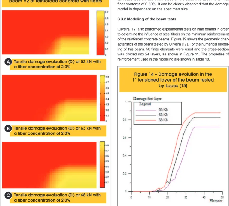
The tension damage distribution in the beam near to service
loading is shown in Figure 13. It can be noted that the increas -ing load also leads to increas-ing damage and dissipates more and more along the beam. Besides, it can be noted that the damage variable already presents high values in the service load state, and in the more tensioned regions it approaches
0.9. This is observed more clearly in Figure 19, which shows
the evolution of damage in the first tensioned layer in the mid-dle span of the beam.
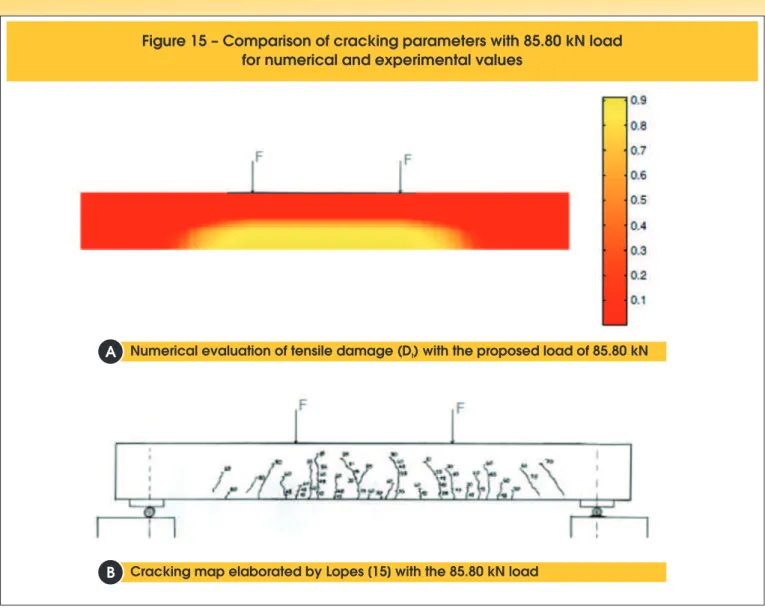
Figure 15 shows a general view of the tension damage distribution
in the beam at the load of 85.8 kN, which evidences a cracking
concentration in the pure lexure region. This behavior is consistent with the cracking pattern observed in the experimental test. On
Figure 10 – Beam numerically tested based on Lopes [15] geometry
Geometry of the beam tested by Lopes [15]
Beam reinforcement tested by Lopes [15]
B
B
A
B
Figure 11 – Schematic representation of the
cross-section of the beam tested by Lopes [15]
the other hand, because the damage model does not consider the
shear contribution, the cracking in the combined shear and lexure
region is not well represented by the numerical modeling.
3.3 Modeling of Oliveira´s Tests [17]
The third numerical example deals with the analysis of a beam tested by Oliveira [17]. Steel ibers A to I were used and their char -acteristics are given in Table 12. Table 13 lists the mechanical properties of the concrete.
3.3.1 Parametric identiication of the damage model
Prismatic specimens with diferent sizes were tested by Oliveira
[17] to evaluate the load–displacement curve. The prismatic speci-mens chosen for numerical analysis in this paper had dispeci-mensions of 150 × 150 × 500 mm (span of 400 mm), 100 × 100 × 400 m (span of 300 mm), and 200 × 200 × 800 m (span of 600 mm).
Prismatic specimens with sizes of 150 × 150 × 500 mm and a iber
content of 1.25% were used to identify the damage parameters. This specimen corresponds to the characterization of the concrete
of the V9 beam tested by Oliveira [17]. Tables 14 and 15 show the parameter values obtained from the damage model. These pa-rameters were kept constant during the numerical analyses and
only the parameters related to the homogenization model were changed. Figure 16 shows the comparison between numerical and experimental responses for the prismatic specimens. The error be
-tween the numerical and experimental peak loads was 1.24%. It is
important to note that the damage model is not capable of repre-senting the mechanical behavior of the beam when dealing with a
high level of displacement due to damage localization.
For the V8 beam with a iber content of 0.75%, the prismatic speci -men of 150 × 150 × 500 mm tested by Oliveira was used again
[17]. The parameter values obtained for the homogenization model are presented in Table 16 and the numerical and experimental curves for the prismatic specimen are presented in Figure 23. For the V7 beam with a iber content of 0.50%, the three sizes of prismatic specimens tested by Oliveira were analyzed [17]. The parameter values for the homogenization model are presented in
Table 17. Note that in this table the parameters are dependent on
the specimen size. Figure 18 shows the numerical and experimen
-tal responses for the three sizes of the prismatic specimens with iber contents of 0.50%. It can be clearly observed that the damage model is dependent on the specimen size.
3.3.2 Modeling of the beam tests
Oliveira [17] also performed experimental tests on nine beams in order to determine the inluence of steel ibers on the minimum reinforcement of the reinforced concrete beams. Figure 19 shows the geometric char
-acteristics of the beam tested by Oliveira [17]. For the numerical model
-ing of this beam, 50 inite elements were used and the cross-section was divided into 24 layers, as shown in Figure 11. The properties of
reinforcement used in the modeling are shown in Table 18.
Figure 13 – Tensile damage evaluation ( ) of
D
tbeam V2 of reinforced concrete with fibers
Tensile damage evaluation (D ) at 53 kN with t
a fiber concentration of 2.0%
Tensile damage evaluation (D ) at 63 kN with t
a fiber concentration of 2.0%
Tensile damage evaluation (D ) at 68 kN with t
a fiber concentration of 2.0%
B
B
B
A
B
C
Figure 14 – Damage evolution in the
1º tensioned layer of the beam tested
Figure 20 shows the numerical and experimental load–displace
-ment curve in the middle span of the V7 beam with a steel iber content of 0.50%. The numerical responses were obtained using the parameters of the homogenization model from three diferent prismatic specimen sizes. The names P450, P600, and P300 refer to the span of the prismatic specimens; that is, P450 refers to the 150 × 150 × 500 mm specimen, P600 to the 200 × 200 × 800 mm specimen, and P300 to the 100 × 100 × 400 mm specimen. Analy -ses were performed in the service load state.
It is possible to note the size efect on the high-level load of the
beam. As this paper is concerned with the mechanical behavior
in the service load state whose results are in agreement with ex -perimental ones, all analyses were performed with parameters
ob-tained from specimen P600.
The maximum experimental load was 111.8 kN and the estimated
service load for the numerical analysis was 44.75 kN. The
displace-ment in the middle span of the beam for the experidisplace-mental service
load was 0.503 mm, whereas the displacement obtained from the
numerical analysis was 0.514 mm, presenting an error of 2%.
Figure 15 – Comparison of cracking parameters with 85.80 kN load
for numerical and experimental values
Numerical evaluation of tensile damage (D ) with the proposed load of 85.80 kNt
Cracking map elaborated by Lopes [15] with the 85.80 kN load
B
B
A
B
Table 13 – Mechanical properties of the concrete beams tested by Oliveira [17]
Beam fcm (MPa) Modulus of elasticity
Ecm (GPa) Poisson ratio (u) Fiber percentage (%)
V7 55.27 51.10 0.21 0.50
V8 53.27 45.20 0.18 0.75
V9 62.33 40.67 0.18 1.25
Table 12 – Steel fiber properties
used by Oliveira [17]
Analysed property Value
Modulus of elasticity (GPa) 200 Tensile resistance (MPa) 1100 Specific weight (kg/m³) 7850
Length (mm) 60
Diameter (mm) 0.75
Figure 21 shows the tension damage distribution near to the load
of 50 kN. Even at small load levels, the beam shows high dam-age values in the middle span due to the small reinforcement rate used in this beam. At that loading level, there is fracture nucleation
in the experimental test. The numerical modeling tries to repro -duce this phenomenon, evidencing a decrease in strength for a load of 55 kN. However, the numerical modeling shows a recovery
of strength and the mechanical behavior of the beam starts to be
inluenced by the homogenization model. Figure 22 illustrates this
phenomenon, presenting a greater increase of the damage in the
irst layer of the beam in the middle span when the load increases
from 50 to 60 kN.
Figure 23 shows the numerical and experimental load–displace
-ment curves for the V8 beam with a iber content of 0.75%. For
Table 14 – Damage parameters and elastic modulus of concrete without fibers identified
from the four-point flexural tests on prismatic specimens of 150 mm × 150 mm × 500 mm
Parameters Tensile Compression Fpico, num (kN) Fpico, num / Fpico, exp
E (MPa) 33700 33700 78.74 1.24%
A 12 0.7 78.74 1.24%
B (Mpa-1) 6500 2.5 78.74 1.24%
YO (Mpa) 0.000003 0.004945 78.74 1.24%
b 0.00000295 0.0003 78.74 1.24%
Table 15 – Model parameters for homogenization of La Borderier [4]
for concrete with 1.25% fibers – Example III
Fiber volume Fpico, num (kN) Peak stress – spic
(MPa)
Yield stress – ss
(MPa)
Strain fracture – erupt
(m/m) Fpico, num / Fpico, exp
1.25% 78.74 430.00 344.00 0.0400 1.24
Table 16 – Model parameters for homogenization of La Borderier [4]
for the beam V8 with 0.75% steel fibers by Oliveira [17]
Fiber volume Fpico, num (kN)
Peak stress – spic
(MPa)
Yield stress – ss
(MPa)
Strain fracture – erupt
(m/m) Fpico, num / Fpico, exp
0.75% 54.31 480.00 384.00 0.040 0.254%
Table 17 – La Borderie [4] parameters for the calibrated curve
of the concrete beam V7 with 0.5% fibers
Fiber
volume Fpico, num (kN) Prismatic specimens
Peak stress – spic
(MPa)
Yield stress – ss
(MPa)
Strain fracture –
erupt (m/m)
Fpico, num / Fpico, exp
0.50% 22.89 100 × 100 × 450 mm 675.00 540.00 0.040 0.180%
0.50% 46.84 150 × 150 × 500 mm 615.00 492.00 0.040 1.134%
0.50% 61.17 200 × 200 × 800 mm 430.00 344.00 0.040 0.015%
Table 18 – Longitudinal reinforcement data used in the modeling
of beams tested by Oliveira [17]
Beam Modulus of elasticity
(MPa) Peak stress – spic (MPa) Yield stress – ss (MPa)
Strain fracture – erupt
(m/m)
V7 210000 729 628 1.115
V8 210000 729 628 1.115
Figure 16 – Numerical curve versus
experimental prismatic specimens of V9 beam
by Oliveira [17] with 1.25% fibers
Figure 17 – Numerical curve versus
experimental prismatic specimens of V8 beam
by Oliveira [17] with 0.75% fibers
this beam, the numerical analysis does not show results after a
load of 80 kN due to the intense damage process. The maximum load applied to this beam was 138.21 kN and a service load equal to 55.29 kN was adopted. For this load, the experimental displace -ment in the middle span of the beam was 0.730 mm, whereas the numerical analysis achieved a displacement of 1.398 mm,
repre-senting an error of 92%. For loads smaller than 53 kN, the dam
-age model presented a smaller error compared to experimental values. For example, an error of just 7% was obtained for a load of
52.11 kN. In this case, the vertical displacement estimated by the
Brazilian Standard NBR 6118 [2014] was 0.510 mm, representing a value 23% smaller than the experimental one.
The numerical and experimental load–displacement curves for the V9 beam are shown in Figure 24. The service load for this beam was estimated as 66.48 kN, which corresponds to an experimental
displacement of 0.844 mm. The numerical modeling presented a
value of 1.56 mm, that is, 87% greater than the experimental val
-ue. For small loads, the numerical modeling presents good results when compared to the experimental ones. For example, an error of 17% is presented for a loading of about 58.62 kN. In this case, the vertical displacement estimated by the Brazilian Standard NBR 6118 [2014] was 0.512 mm, which represents a value 30% smaller than the experimental one.
In order to evaluate a possible inluence of the steel iber orienta -tion, the three beams tested by Oliveira [17] were simulated again
in order to ind new parameters for the homogenization model. In this case, the inverse analysis was performed on the experimental
response of the beams and not on the prismatic specimen response.
Figures 25 to 27 show the load–displacement curves for the new
parameters of La Borderie’s model [4], which are shown in Table 19.
First of all, there is a better approach for the maximum numeri
-cal load to the maximum experimental load. However, a diference between the numerical and experimental responses after the dam
-age localization in the middle of the span is still noted. This diver
-gence tends to decrease with increasing the steel iber content due
to a more distributed cracking along the tested beams. Another
important observation is that the parameters of the homogeniza
-tion model vary with the iber content, as one would expect from La
Borderie’s model. However, these parameters show a little
varia-tion for iber contents greater than 0.75%, which approximately represents the critical iber content for this concrete matrix.
4. Conclusions
First of all, it is important to note that the damage model is capable
of dealing with structures in service loading state. It is possible to
Table 19 – Model parameters of homogenization by La Borderier [4] obtained
by retro-analysis of the beams tested by Oliveira [17]
Beam Fiber volume
(%) Fpico (kN)
Peak stress – spic
(MPa)
Yield stress – ss
(MPa)
Strain fracture –
erupt (m/m)
Fpico, num / Fpico, exp
V7 0.50 110.21 220.00 187.00 0.020 1.49%
V8 0.75 130.88 240.00 204.00 0.020 5.69%
Figure 18 – Numerical curve versus experimental prismatic
specimens of V7 beam by Oliveira [17] with 0.50% fibers
Prismatic specimens of
100 mm × 100 mm × 450 mm Prismatic specimens of 150 mm × 150 mm × 500 mm
B
B
A
Prismatic specimens of 200 mm × 200 mm × 800 mm
B
C
B
observe that in the service loading state (deined in this paper as about 40% of the ultimate loading), the numerical model presented good results compared to experimental tests.
Another factor observed in all examples is the massive process
damage in the more tensioned layers even under service loading
state. The constitutive model represents the cracking pattern of
beams under lexure well. As the cracking process intensiies, it
naturally leads to fracture nucleation. Thus, as the loading
Figure 19 – Beam numerically tested based on Oliveira's [18] geometry
Beam geometry tested by Oliveira [18]
Beam reinforcement tested by Oliveira [18]
B
B
A
B
Figure 20 – Numerical and experimental curves
of beam V7 of Oliveira [17]
Figure 21 – Damage by tensile (D )
tin beam V7 of Oliveira [17] for
a specific strength
44.75 kN strength
B
A
60.00 kN strength
B
Figure 22 – Comparison of damage
in the first layer of beam V7
Figure 23 – Load versus numerical
and experimental displacement
of beam V8 of Oliveira [17]
Figure 24 – Load versus numerical and
experimental displacement of beam V9
of Oliveira [17]
Figure
26 – Parametric identification through
beam V8 with 0.75% fibers
Figure 27 – Parametric identification through
beam V9 with 1.25% fibers
problems. In fact, these problems arise after the service loading state. This feature is more pronounced in concrete prisms with or
without low values of iber content, in which there is nucleation of localized fractures in the absence of reinforcement. Therefore, the damage model cannot capture the efect of strain localization. In
future work, the authors intend to propose a two-dimensional mod-eling coupling a fracture model with the damage model in order to
investigate the localization problem described here.
The parametric identiication of a constitutive model is one of the
most important features involved in computational modeling of structures. It is observed that the responses obtained from beam
modeling in the third example are not satisfactory with regard to
the softening behavior. In addition, the damage model does not consider the fracture nucleation, another important observation
concerns the possible inluence of the size efect and the iber ori
-entation. In both the second and the third example, the parametric identiications were performed in prismatic specimens with dimen -sions smaller than those of the beams. As the damage model does not take into account those two factors, it may be that the
numeri-cal response was afected and the numerinumeri-cal strength was greater than the results obtained from experimental tests. The change of prismatic size of the V7 beam in the third example led to changes of the homogenization parameters and consequently changes in
the numerical response of the beam.
The inluence of the size efect and iber orientation can be more pro
-nounced when the parameters of the homogenization model have been
obtained from inverse analysis of the beams. In this case, a reduction of
the maximum load obtained from numerical modeling, which was near
-est to the experimental values, was observed. This sugg-ests that fewer
steel ibers were oriented in the longitudinal direction of the beams. The increase in the maximum load of the beams in the third example was not proportional to the increase in iber content. On the other hand, the
parameters obtained from the inverse analysis of prismatic specimens
in the second example were adequate to represent the service state of the beam, as well as the maximum experimental load. This feature can be explained by the similarity of the cross-section dimensions of the specimen and the beam in this example.
Finally, it can be concluded that the damage model can be applied in the analysis of steel-iber-reinforced concrete beams once the numerical responses show good agreement with the experimental
results, mainly in service loading state. In a preliminary analysis, if the proposed damage model response is compared with the
displacement evaluated from the Brazilian Standard NBR 6118
[2014], the damage model tends to provide values of displacement
closer to those observed in the experimental tests. However, this
assertion needs to be better investigated in future works.
5. Acknowledgments
Financial support from CAPES Foundation, the Ministry of Educa
-tion of Brazil, and CNPq (Na-tional Council for Scientiic and Tech
-nological Development) is gratefully acknowledged.
6. References
[1] MATALLAH, M.; LA BORDERIE, C.
Engineering Fracture Mechanics, v. 76, pp. 1087–1108,
2009.
[2] BIELSKI, J.; SKRZYPEK, J. J.; KUNA-CISKAL, H. Imple -mentation of a model of couled elastic-plastic unilateral
dam-age material to inite element code. International Journal of Damage Mechanics, v. 15, pp. 5–39, 2006.
[3] PITUBA, J. J. C.; FERNANDES, G. R.. Anisotropic damage
model for concrete. Journal of Engineering Mechanics, v. 137, pp. 610–624, 2011.
[4] LA BORDERIE, C. Phenomenes unilateraux dans un mate -riau endommageable: modelisation et application a l’analyse
de structures en beton. Tese (Doutorado em Engenharia), Universidade de Paris, Paris, 1991, 140 p.
[5] LI, F., LI, Z. Continuum damage mechanics based modeling of iber reinforced concrete in tension. International Journal
of Solid and Structures. Hong Kong, v. 38, p. 777–793, 1999.
[6] LEE, H. K., LIANG, Z. Computational modeling of the re
-sponse and damage behavior of iber reinforced cellular
concrete. Computers & Structures. USA, v. 82, p. 581–592, 2004.
[7] HAMEED, R., SELLIER, A., TURATSINZE, A., DUPRAT, F. Damage modeling of metallic iber-reinforced concrete. En
-gineering Procedia. France, v. 10, p. 1670–1678, 2011. [8] PASA, V. F. Análise do comportamento de estruturas de con
-creto reforçado com ibras de aço via método dos elemen
-tos ini-tos. Dissertação (Mestrado em Engenharia de Estru
-turas), Universidade Federal do Rio Grande do Sul, Porto
Alegre, 2007, 130 p.
[9] GUELLO, G. A. Simulação computacional de estruturas de
concreto por meio da mecânica do dano. Dissertação (Mes
-trado em Engenharia de Estruturas), Escola Politécnica de São Paulo, Universidade de São Paulo, São Paulo, 2002,
105 p.
[10] PITUBA, J. J. C. Sobre a formulação de um modelo de dano para concreto. Tese (Doutorado em Engenharia de Estrutu -ras), Escola de Engenharia de São Carlos, Universidade de
São Paulo, São Paulo, 2003, 151 p.
[11] COMI, C.; PEREGO, U. A bi-dissipative damage model for
concrete with applications to dam engineering. European Congress on Computational Methods in Applied Sciencs and Engineering (ECOMAS 2000), 2000.
[12] RAMTANI, S.; BERTHAUD, Y.; MAZARS, J. Orthotropic be
-havior of concrete with directional aspects: modeling and ex
-periments. Nuclear Engineering Design, v. 133, pp. 97–111,
1992.
[13] VELASCO, R. V. Concretos auto-adensáveis reforçados
com elevadas frações Volumétricas de ibras de aço: pro
-priedades reológicas, Físicas, mecânicas e térmicas. Tese (Doutorado em Ciências em Engenharia Civil), Universidade Federal do Rio de Janeiro, 2008, 349 p.
[14] ABNT – ASSOCIAÇÃO BRASILEIRA DE NORMAS TÉCNI
-CAS. NBR 15530: Fibras de aço para concreto – Especiica -ção. Rio de Janeiro, 2007, 7 p.
[15] LOPES, M. M. Substituição parcial de armadura de lexão por ibras de aço em vigas de concreto. Dissertação (Mes
-trado em Engenharia Civil), Universidade Federal do Rio de
Janeiro, Rio de Janeiro, 2005, 155 p.
[16] PEREIRA JUNIOR, W. M. Análise numérica de estruturas de
concreto com ibras utilizando mecânica do dano. Disserta -ção (Mestrado em Geotecnia, Estruturas e Constru-ção Civil s), Escola de Engenharia Civil da Universidade de Goiás,
Universidade Federal de Goiás, Goiânia, 2014, 157 p. [17] OLIVEIRA, C. A. S. Avaliação da redução de armadura mín
-ima de lexão em vigas de concreto armado com adição de ibras de aço. Dissertação (Mestrado em Engenharia Civil), Universidade Federal de Goiás, Goiânia, 2008, 231 p. [18] BENTUR, A., MINDESS, S. Fiber Reinforced Cementitious
![Figure 1 – Finite element applied to Pituba's computer code [10]](https://thumb-eu.123doks.com/thumbv2/123dok_br/18861296.417970/2.892.454.828.722.1127/figure-finite-element-applied-to-pituba-computer-code.webp)

![Table 2 – Mechanical properties of concrete studied by Lopes [15]](https://thumb-eu.123doks.com/thumbv2/123dok_br/18861296.417970/5.892.72.832.733.1145/table-mechanical-properties-of-concrete-studied-by-lopes.webp)
![Table 8 – Mechanical properties of concrete obtained by Lopes [15] and used in numerical modeling](https://thumb-eu.123doks.com/thumbv2/123dok_br/18861296.417970/9.892.60.836.33.844/table-mechanical-properties-concrete-obtained-lopes-numerical-modeling.webp)