A
rti
g
o
*e-mail: [email protected]
IN SITU PREPARED TiO2 NANOPARTICLES CROSS-LINKED SULFONATED PVA MEMBRANES WITH HIGH
PROTON CONDUCTIVITY FOR DMFC
Jignasa N. Solanki, Preeti S. Mishra and Zagabathuni Venkata Panchakshari Murthy*
Department of Chemical Engineering, Sardar Vallabhbhai National Institute of Technology,Surat – 395 007, Gujarat, India
Recebido em 25/11/2015; aceito em 18/02/2016; publicado na web em 29/04/2016
Organic/inorganic membranes based on sulfonated poly(vinyl alcohol) (SPVA) and in situ prepared TiO2 nanoparticles nanocomposite
membranes with various compositions were prepared to use as proton exchange membranes in direct membrane fuel cells. Poly(vinyl alcohol) (PVA) was sulfonated and cross-linked separately by 4-formylbenzene-1,3-disulfonic acid disodium salt hydrate and glutaraldehyde. The ion exchange capacity and proton conductivity of the membranes increased with increasing amount of TiO2
nanoparticles. The composite membranes with 15 wt% TiO2 exhibited excellent proton conductivity of 0.0822 S cm-1, as well as
remarkably low methanol permeability of 1.11×10⁻⁹ cm2 s-1. The thermal stability and durability were also superior and performance
in methanol fuel cell was also reasonably good.
Keywords: TiO2 nanoparticles; sulfonated PVA; proton exchange membrane; direct methanol fuel cell; methanol permeability.
INTRODUCTION
Direct methanol fuel cells (DMFCs) is a promising technology for clean and efficient power generation.1 Proton exchange membranes (PEMs) are the key components in fuel cell system. At present, Nafion, perfluorinated sulfonic ionomers are used most commonly in DMFCs, attributed to high proton conductivity, and high thermal and chemical stability when hydrated. Nevertheless, efficiency of DMFC is limited due to the use of Nafion, because it allows high methanol crossover. In addition, Nafion is expensive and major cost of the entire DMFC is accountable to Nafion based membrane itself.2 These membranes are also mechanically unfavorable at higher temperatures.3,4 Hence, there is a great need of alternative to Nafion based membrane, which is inexpensive, efficient and stable. The best alternative can be composite systems prepared with economical base polymer. In composite sys-tems, active components are hooked on to the base polymer matrices.5 Composite system can also have improved durability and they can exploit the electronegative environment provided by the base polymer matrices. This is a key direction in which future research endeavors are focused for getting low cost proton exchange membrane (PEM), which can give better alternative to Nafion.
Poly(vinyl alcohol) (PVA) and sulfonated poly(ether ether ketone) (SPEEK) are the most cheap polymer, which can be used as base poly-mer. A few studies have successfully explored the use of PVA, such as phosphotungstic acid doped poly(vinyl alcohol)/poly(ether sulfone) blend,6 poly(vinyl alcohol)/para-toluene sulfonic acid membranes,7 poly(vinyl alcohol)/poly(ether sulfone) blend composite membranes, and cross-linked PVA/polyacrylic acid/silica hybrid membranes.8 A few reported studies have also successfully explored the use of SPEEK, such as cross-linked SPEEK/2-acrylamido-2-methyl-1-propanesulfonic acid (AMPS) blend membranes,9 SPEEK/PVDF blends10 and SPEEK/phenoxy resin (PHR) membranes.11 As sulfona-tion of base polymer can reasonably increase the proton conductivity,12 many of the above reported work have attempted sulfonation of base polymer. However, majority of work reported on PVA sulfonation, have reported the use of sulfonating agent containing both sulfonic and acid group (e.g., sulfosuccinic acid, sulfoacetic acid, etc).13 Such types of sulfonating agents were responsible for both cross-linking
and sulfonation. However, while using such sulfonating agents, the degree of PVA sulfonation cannot be controlled and higher degree of sulfonation leads to higher methanol permeability, which is not desirable.14 Therefore, to optimize sulfonation, the usage of separate sulfonating agent and cross-linking agent can be preferred.
In addition, hygroscopic metal oxide particles, such as SiO2, ZrO2 or TiO2, in small quantity can be added into base polymer matrix to prepare organic-inorganic composites PEMs. Such addition can keep a certain relative humidity (RH) to maintain normal operation of cells even when the temperature is above 100 °C.15 Not only that, such addition leads to an increased water uptake, which helps in proton transfer, and ultimately it leads to high power density of DMFC. Water adsorbed on the surface of the oxides effectively decreases the electro-osmotic drag by enhancing the back diffusion of the cathode produced water. Hygroscopic oxides can act as self-humidifying agents, which facilitates the water uptake. High water uptake of membrane gives high resistance to methanol permeation and hydrogen bond between water molecules helps in proton transfer. In addition, it also gives high surface area for proton transfer and it increases the thermal and mechanical stability of PEMs.16
Few studies are reported in literature on the composite PEMs preparation, however, readily purchased nanoparticles are used in those reports.17-22 Many modifications on Nafion with differ-ent nanoparticles have been reported,17-19 however, it makes the PEM more costly. Therefore, combination of low cost of inorganic nanofillers and base polymer can be a good substitute for low cost PEM. Literature on the addition of TiO2 nanoparticles in low cost PVA is feeble. Yang20 prepared cross-linked PVA/TiO
2 composite membrane for DMFC. However, PVA was not sulfonated and the prepared membranes depicted minor increase in ionic conductivity. The resulting power density (7.54 mWcm−2) was also not very high; on the contrary, it was less than that of Nafion membranes (171 mWcm−2). Yang et al.21 have prepared the PVA polymer directly blended with nanosized montmorillonite (MMT) filler and observed limited increase in ionic conductivity (0.0368 S cm−1 at 30 °C), as well as limited decrease in methanol permeability (3−4×10⁻⁶ cm2 s−1). Yang et al.22 again modified the work using PVA/TiO
2 nanotubes/ poly(styrene sulfonic acid). However, the highest proton conduc-tivity observed was 2.52×10⁻³ S cm−1. Hence, further increase in proton conductivity is still desirable. Matos et al.23-25 also used TiO
as nanofiller. Matos et al.23 have prepared Nafion-based composites and also explained irreversibility of proton conductivity application in high temperature polymer electrolyte fuel cells.Nafion-nanotube nanocomposite membranes are also attempted by in situ crystal-lization, and have been shown to be of great potential for fuel cells operating at intermediate temperature (<130 °C).25 Nafion-titania composite was also successfully prepared and was shown to give high efficiency and lower ethanol uptake.24 Overallsuperior performance was observed with the use of titania as nanofiller, however, Nafion was used as base polymer.
Hence, in the present paper, we have utilized freshly prepared TiO2 nanoparticles as nanofiller with PVA as base polymer. The PVA is firstly sulfonated and then used to prepare nanocomposite mem-branes. In situ preparation of optimum and suitable size nanoparticles were carried by sol-gel method as reported in our previous work.26 Furthermore, to optimize sulfonation, separate sulfonating agent and cross-linking agent are used. The 4-formylbenzene-1,3-disulfonic acid disodium salt hydrate (DSDSBA) is used to achieve appropri-ate degree of sulfonation of PVA and glutaraldehyde (GA) is used separately as cross-linking agent. These may lead to reduced methanol permeability, increased proton conductivity and increased thermal stability, which is highly desirable.
EXPERIMENTAL
Materials
The poly(vinyl alcohol) (PVA, 99% hydrolyzed), titanium te-trachloride (TiCl4), dimethyl sufoxide (DMSO) and glutaraldehyde (GA) were purchased from Thermo Fisher Scientific Pvt Ltd., India. 4-Formylbenzene-1,3-disulfonic acid disodium salt hydrate (DSDSBA) was purchased from Tokyo Chemical Industries, Japan. All the chemicals were of analytical grade and were used without any further purification.
Synthesis of TiO2 nanoparticles and synthesis of nanocomposite membranes
Firstly, TiO2 nanoparticles were prepared for utilization in PEM membrane preparation, as described in our previous work.26 Basically, solution of TiCl4 in ethanol (10 wt%) at 27 °C were taken and TiCl4 was added drop wise. A light yellow solution was obtained after adding the required TiCl4. The solution was then gelatinized by stirring for 4 h and the resulted solution was kept for aging for 3 h at room temperature. Resulted gel solution was kept for sonication in ultrasonic bath for 30 min at a frequency of 45 kHz and a power of 60 W. The solution was dried at 80 °C to get dry gel. Finally, the dry-gel precursor was calcined at 450 °C for 1 h to obtain TiO2 nanoparticles. The PEM was prepared using solution casting method. Sulfonated PVA (SPVA) was synthesized via sulfonation reaction, in a 500 mL three-necked flask equipped with a magnetic stirrer and a nitrogen inlet. A 5 g of PVA was dissolved in 45 mL DMSO at 70 °C. A required amount of DSDSBA was dissolved in DMSO and was added in the PVA solution. Required amount of TiO2 nanoparticles (5 wt%) were dissolved in DMSO and was kept for sonication for 20 min at 45 kHz and a power of 60 W for uniform dispersion. Then, it was added slowly to PVA solution and the whole solution was kept at 80 °C for 20 h with continuous stirring. After cooling to room temperature, the obtained TiO2-sulfonated PVA was casted on a glass plate, which was subjected at 30 °C for solvent evaporation for 8 h, and then it was dried at 80 °C for 2 h and finally dried at 100 °C for 1 h. When the membrane was completely dried, the peeled pieces of membrane were cross-linked. The cross-linking reaction
was performed by soaking the SPVA membranes for 1 h at 40 °C in a cross-linking solution containing 0.25% GA, HCl as an acid catalyst and acetone. After the reaction, the cross-linked membranes were washed with acetone and dried under vacuum at 40 °C for 24 h. Similarly, different amounts of in situ prepared TiO2 nanoparticles were dissolved in DMSO to obtain membranes with different wt% of TiO2 nanofillers(10, 15 and 20 wt%).
CHARACTERIZATION METHODS
Nanoparticles characterization
The sizes of TiO2 nanoparticles were measured by Nano Zetasizer-ZS90, which performs size measurements by dynamic light scattering (DLS; Malvern Instruments, UK). The size was also determined by transmission electron microscope (TEM) at accelerating voltage of 200 kV (Tecnai 20; Philips, Holland) to obtain the images of the prepared TiO2 nanoparticles. X-Ray diffraction (XRD) of TiO2 nanoparticles was also performed by X-ray diffractometer (X’Pert Pro, PANalytical, Holland) at 40 kV and 30 mA.
Membranes characterization
Water uptake
Initially, 3 g of dry SPVA nanocomposite membrane was weighed and the membrane was soaked in deionized water for 24 h, at room temperature. After 24 h, the membrane was wiped with tissue paper and another weight measurement was taken immediately. Water uptake was calculated using the following formula:
(1)
where W is the water uptake measured as a percentage, Wwet is the weight of the soaked membrane, and Wdry is the weight of the dry membrane.
Ion exchange capacity
Ion exchange capacity (IEC) of the membranes was evaluated by titration technique. A 4 g of the sample was soaked in 0.1 mol L-1 NaCl solution for 24 h for the exchange of protons and sodium ions. Titration was performed using 0.1 mol L-1 NaOH aqueous solution with phenolphthalein indicator to estimate the amount of ions gene-rated during the ion exchange process. IEC was calculated using the following equation:
(2)
where CNaOH is the concentration of NaOH, VNaOH is NaOH volume consumed and Wdry is the dry weight of the membrane.27
Methanol permeability
The samples drawn from compartment B were used to measure the concentration of methanol as a function of time using gas chromato-graphy (PerkinElmer; Clauras 500, USA) with FID temperature 260 °C, oven temperature 180 °C and 1.6 mL min-1 flow rate of carrier gas. Methanol permeability was calculated using the following equation:
(3)
where P is the methanol permeability (cm2 s-1), VB is the volume of DW (cm3), L is the thickness of the membrane (cm), A is the area of the membrane (cm2), CA and CB are concentrations of methanol in compartments A and B, respectively, and (dCB)/dtis the slope of the methanol concentration over time (s).28
Proton conductivity
Proton conductivity of the membranes was calculated by mem-brane resistance which was measured by AC Impedance Analyzer (CHI 608c, USA) over a frequency range of 100 MHz to 100 kHz with oscillating voltage of 5 mV. The membrane samples were soaked in deionized water for 12 h. A 2×2 cm2 of membrane was taken for the measurement. Proton conductivity is measured by a method described elsewhere.29 Then using two probe method, the AC impedance was measured. Proton conductivity was measured using the following formula:
(4) where σ is the proton conductivity (S cm-1), R is the bulk resistance
of the membrane, S is the cross-sectional area (cm2) and L is the membrane thickness (cm).
Surface morphology, FTIR and thermal analysis
The morphology of membrane samples was evaluated by scanning electron microscopy (SEM) analysis. The samples were imaged in SEM (JSM-7600F) at two different magnifications (x500 and x45,000). Before imaging, cross-linked SPVA membranes were coated with platinum at 10 mA current for 60 s and 2 nm thick layers was obtained. Chemical structure evaluation was done by FTIR analysis using Nicolet Instruments Corporation, USA-MAGNA 550. The membrane samples were analyzed between wave number of 4000 and 400 cm-1. Thermo gravimetric differential scanning (TG-DSC) of the samples was carried out to examine the % weight loss of the cross-linked membranes. Four milligrams of the samples were heated from 25 to 900 °C at a heating rate of 10 °C min-1 under nitrogen atmosphere. Molybdenum disilicide was the heating filament with alumina lining.
RESULTS AND DISCUSSION
Optimum and suitable TiO2 nanoparticles
In the present work, freshly prepared TiO2 nanoparticles are uti-lized in the form of inorganic nanofillers to prepare nanocomposite PVA membranes. In our previous work,26 optimum and suitable TiO
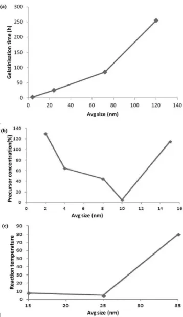
2 nanoparticles for addition as inorganic nanofillers were prepared by sol-gel method. To obtain optimum size nanoparticles, the important operating parameters were varied. The sizes and morphology of TiO2 nanoparticles were measured by dynamic light scattering (DLS) method and transmission electron microscopy as reported in detail in our previous work.26 The variation in the average size of nanoparticles
obtained is shown in Figure 1. The average size of nanoparticles was basically obtained by variation ingelatinization time (4 – 120 h), concentration of precursor (TiCl4) in ethanol (2 – 15 volume%), and reaction temperature (15– 35°C).
Figure 1 clearly depicts that the optimum size and suitably uniform TiO2 nanoparticles were obtained at 4 h of gelatinization time, at 10% precursor concentration (TiCl4) and at 25°C reaction temperature, which were of 1-13 nm size. Consequently, these in situ prepared nanoparticles were added as nanofillers for further nanocomposite PEM preparation.
X-Ray diffraction analysis of TiO2 nanoparticles
The X-ray diffraction (XRD) measurement was performed to examine the structure of TiO2 nanoparticles (Figure not shown). It is observed that nanoparticles are amorphous and anatase phase.30-32 Surface morphology of membranes
Figure 2 shows the SEM images of prepared membranes.
Figure 1. Average size of TiO2 nanoparticles synthesized with variation in
gelatinization time (4, 24, 72 and 120 h), volume% concentration of precur-sor (TiCl4) in ethanol (2, 4, 8, 10 and 15%), and reaction temperature (15,
Figure 2(a) shows the morphology of cross-linked PVA membra-ne. It is a clean and uniform surface. This membrane was coated for three times being highly non-conductive in nature. Figure 2(b) shows the morphology of nanocomposite SPVA membrane, and the same structure at high magnification is shown in Figure 2(c), which shows clearly few white spots and dark spots. White dots indicate the presence of TiO2 nanoparticles and dark dots indicate the presence of ionic clusters.33 These ionic clusters are essentially formed due to the sulfonation of PVA. Essentially, formation of ionic clusters are attributed to proper high degree of sulfonation and it results in better proton transfer pathways compared to that with less degree of sulfonation or than that of non-sulfonated ones. From Figure 2(b), it
can be seen that these ionic clusters are well dispersed in the mem-brane and properly arranged. These properly arranged ionic clusters will further lead to large extent of proton conductivity enhancement compared to randomly arranged ionic clusters. TiO2 nanoparticles (white dot like structure) help to absorb water on its surface and provide resistance to methanol permeability. Hence, it is evident from Figures 2(b) and 2(c), that the degree of sulfonation and the amount of added nanofillers (TiO2 nanoparticles), both are reasonable, which may lead to desired properties such as high ionic conductivity, high water uptake, and low methanol permeability.
Evaluation of chemical structure
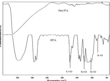
Figure 3 depicts the schematic representation of nanocomposite membrane prepared in the present work. It clearly shows that the base membrane PVA contains chain of C. Figure 3 also depicts the chemical structure after sulfonation. Basically, after sulfonation, S is also appeared in chemical structure. In addition, Figure 3 also depicts the presence of Ti in chemical structure of nanocomposite membrane after the addition of TiO2 as nanofiller. The presence of S is also further confirmed with FTIR and the degree of sulfonation is evaluated. Figure 4 depicts spectra of pure PVA and SPVA mem-branes. Broad absorption bands are observed in both pure PVA and SPVA membranes. The spectrum range of pure PVA membrane is observed to be in the range of 3600 to 2700 cm−1, due to the O–H stretching mode in the hydroxyl groups (–OH). While, spectrum range of SPVA membrane is observed to be in the range of 3400 to 2900 cm−1 attributed to the asymmetric –CH
2 stretching band in the PVA matrix.34 Few new peaks also appeared in spectra of SPVA membrane, as seen from Figure 4. The peaks at stretching vibrations of 1244, 1137 and 1024 cm−1 confirms sulfonation of PVA.33,35-37 The peak at 1244 and 1024 cm−1 are attributed to asymmetric stretching vibrations of S=O in the sulfonic acid group.34 The C=O stretching peak of carboxyl acid groups is viewed at 1736 cm−1 which confirms the cross-linking of membrane.35 The peak at 798 cm−1 is attributed to the presence of S-O group.33,35-37 Hence, it is confirmed that the prepared membrane is properly sulfonated as well as cross-linked.
Thermal properties and thermal stability
Thermal stability or thermal property of membrane is a key property of membrane. High temperature operation of membranes in DMFC is a key demand in today’s market. Basically, membrane used in the DMFC should contain high thermal stability. However, the low cost base PVA used in the present work has low stability. Furthermore, upon cross-linking PVA, stability is negligibly increased.36 Hence,
Figure 2. SEM images of membranes: (a) pure PVA membrane; (b) SPVA membrane at 500X; and (c) SPVA membrane at 45000X
to achieve high stability, nanocomposite preparation of cross-linked sulfonated PVA is attempted in the present work by the addition of TiO2. Different wt% of TiO2 nanofillers were added to obtain diffe-rent SPVA composite polymer membrane. The SPVA (5%), SPVA (10%), and SPVA (15%) were prepared with 5, 10 and 15 wt% TiO2, respectively. Figure 5 shows thermogravimetric differential scanning (TGA) analysis thermographs of the SPVA polymeric membrane alone, and composite polymer membranes SPVA (5%), SPVA (10%) and SPVA (15%).
TGA thermograph of pure SPVA polymer membrane without cross-linking reveals mainly three weight loss regions. The first weight loss region can be seen in temperature range 80-120 oC, which is due to the absorbed water molecules. As can be seen in Figure 5, for the PVA/DSDSBA (SPVA) and PVA/DSDSBA/TiO2 membranes, the second weight loss region (occurring between temperatures of T= 350-490°C) corresponds to the desulfonation and the resulting breakage of the cross-linked bonds (i.e., the –CO–O– bonds). In the third weight loss region (at temperatures >490 °C), the polymer resi-dues were further degraded, which corresponds to the decomposition of the main chains of the PVA. In the case of various hybrid composite membranes with different TiO2 content, the weight remaining after the polymer decomposition depended on the content of the inorga-nic nanofillers and the degree of cross-linking. That is, the weight
residue of hybrid membranes containing TiO2 was higher than that of membrane without the presence of TiO2. These results suggest that the introduction of TiO2 and the degree of cross-linking into the PVA chains enhance the thermal stability of the given hybrid materials. These results are in line with the results reported in literature.15
The Td 5 and T
d
10 (temperatures corresponding to weight losses of 5 and 10%, respectively) are also observed to be low in absence of nanofillers (see Table 1). With the addition of nanofillers Td
10 was observed to be quite high (for SPVA(15%), Td10 =184.1°C), which also indicates increased stability upon increase in nanoparticles concentration. This is reasonably good, as highly enhanced thermal stability (upon addition of nanoparticles) is achieved in the working temperature range of DMFC, as explained above,38,39 because the common operating temperatures are in the range 50-120 °C for DMFC. Furthermore, existence of TiO2 nanoparticles in polymer structure increases polymer matrix crystallinity, which limits the movement of chain segment of polymer. Thus, the thermal stability of the membrane would be increased. Hence, it is clear that the thermal stability of SPVA (15%) is much higher at low temperature range. In addition, however, the weight loss at temperature higher than com-mon operating temperature is little severe for SPVA (15%), but high temperature conditions are commonly not used in DMFCs. This is because DMFC at high temperatures requires to be pressurized ge-nerally. These conditions of high temperature and pressure lead to so many losses in the complete system, which deteriorate the efficiency itself. Therefore, relatively atmospheric-pressure configurations are currently preferred.
Ion exchange capacity and water uptake of membranes
Figure 6 shows the ion exchange capacity (IEC) and water uptake of pure PVA membrane, pure SPVA membrane, and hybrid composite membranes. Due to the absence of any tendency to transform ions, pure PVA membrane depicted very small IEC (0.08 meq g-1), in spite of being cross-linked. On the other hand, sulfonated PVA depicted great increase in IEC (0.99 meq g-1), which is attributed to high and appropriate sulfonation of PVA. Addition of TiO2 nanofillers depicted further increase in IEC to 1.0 meq g-1 for SPVA (5%). Consequently, the concentration of TiO2 nanoparticles was increased, and cor-responding ion exchange capacity was observed to be increased. Interestingly, excellent IEC (1.01 meq g-1) is observed for SPVA (15%) composite PEM,which is even higher than that reported for Nafion 117 based membrane (0.91 meq g-1).40Nevertheless, it has been reported that TiO2 nanoparticles do not enhance IEC.
41 However, as seen from Figure 2(b), addition of TiO2 nanoparticles do not affect the presence of ionic clusters formed by sulfonation of PVA, but hydration of membrane and ionic clusters formed due to sulfonation of PVA may lead to increased IEC. This is in line with the previously reported work on other nanofiller.15
As seen from Figure 6, high water uptake is revealed for pure PVA membrane, as PVA is hydrophilic in nature. When pure PVA
Figure 4. FTIR of PVA membrane and SPVA membrane
Figure 5. TGA of nanocomposite PEMs: SPVA (5%), SPVA (10%) and SPVA (15%)
Table 1. Weight losses of various nanocomposite PEMs
Type of com-posite PEMs
Temperature at weight losses (%) Td
5 T
d
10 T
d
15 T
d 20
SPVA (0%) 81.83 oC 111.88 oC 139.6 oC 191.22 oC
SPVA (5%) 93.84 oC 139.66 oC 168.73 oC 194.70 oC
SPVA (10%) 106.84 oC 147.30 oC 176.57 oC 218.37 oC
SPVA (15%) 112.82 oC 184.10 oC 258.57 oC 284.6 oC
Td 5, T
d 10, T
d 15, T
d
20 are temperatures corresponding to weight losses of 5, 10,
membrane was cross-linked using GA, it revealed low water uptake. When the sulfonation of PVA is performed, the water uptake was increased due to the decrease in hydrophilic group. In the present work, water uptake increased with increase in concentration of TiO2 nanoparticles (see Figure 6). Since TiO2 is hygroscopic in nature, addition of TiO2 may lead to an effective increase in water uptake. Basically, homogeneous dispersions of inorganic fillers into sulfo-nated polymers are known to generate composite membranes with improved morphological stability induced by hydrogen bonding and/ or electrostatic interactions, thus allowing to maintain conducting properties without excessive swelling at T > 100 °C.42-46
Water uptake is found to be 123.1% in SPVA (15%) membrane, attributed to higher concentration of TiO2. On further increasing con-centration of TiO2, SPVA (20%) was showing excellent water uptake (not included in Figure 6). However, very high degree of water uptake (although helps in proton transfer, at the same time) also weakens the membrane during the operation. Thus, it is necessary to find optimum water uptake. Therefore, the water uptakes of these membranes are optimized with respect to strength and conductivity of membrane. Proton conductivity and methanol permeability
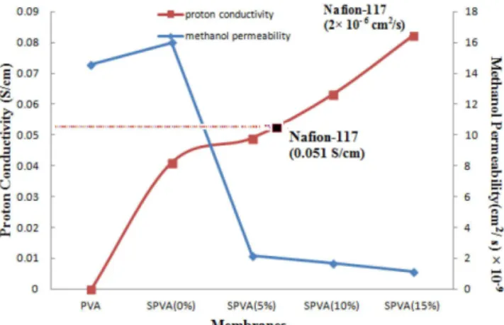
Proton conductivity is a function of ion exchange capacity and water uptake. Higher value of IEC and water uptake supports higher proton conductivity. Figure 7 depicted variation in proton conductivity and methanol permeability of membranes. As observed from Figure 7, nanocomposite membranes demonstrate a significant improvement over the SPVA membrane. Moreover, proton conduc-tivity increased with increase in concentration of TiO2 nanoparticles fillers. Reasonably increased proton conductivity (0.0822 S cm-1) is observed for SPVA (15%) composite polymer membrane.This is much higher than the reported proton conductivity for Nafion-117 based membrane (0.051 S cm-1)47 at room temperature. This increase in proton conductivity can be attributed to higher water uptake. As the water uptake increases, hydrogen bond between water molecules helps in proton transfer. The increase in conductivity can be also attributed to the high specific area (greater number of protonated sites per unit mass of powder in the membrane) and good water retention of hydrophilic TiO2 nanoparticles, which result in higher conductivity compared to bare PVA.48 The proton migration in PEMs primarily occurs by two mechanisms, namely Grotthuss and vehicular mechanisms. In Grotthuss mechanism, protons hop from the H3O
+ donor acid site to any neighboring acceptor water molecule. While in vehicular mechanism, protons transfer by the hy-dronium ions.49-51 In other words, proton transfer agent is immobile in Grotthuss mechanism, whereas, the same is mobile in vehicular
mechanism. Besides, water is essential for good conduction in both mechanisms. Hence, hygroscopic nature of TiO2 particles may lead to an increase in proton conductivity (with increase in water uptake) at increased TiO2 content.
Figure 7 shows the variation in methanol permeability of various membranes. It is clearly evident that nanocomposite SPVA membra-nes possessed excellent methanol resistance. Higher the methanol resistance, lower will be the permeability. Methanol permeability was determined by investigating concentrations of methanol (CB) in compartment B (containing water). Then a plot of the concentration CB vs. time was used to calculate methanol permeability as discus-sed earlier (in Methanol permeability subsection under Membrane characterization section) (as this factor can approximately show a similar trend of permeability). The membrane of the DMFC can utilize high methanol concentrations at low methanol permeability. But the decrease in methanol crossover comes at cost of decrease in conductivity. Higher sulfonation decreases the hydrophobic sites of PVA, hence permeability increases. But doping of nanofillers shows a different trend. These nanoparticles demonstrated resistance to methanol permeation. As a result, low methanol permeability resul-ted in an excellent effective energy density in the DMFC system. The methanol permeability of the membranes found in the present work decreased reasonably from 1.59×10⁻⁸ cm2 s-1 (SPVA (0%)) to 1.11×10⁻⁹ cm2 s-1 (SPVA (15%)). These values are remarkably lower than Nafion117 (2×10⁻⁶ cm2 s-1).52 The water and methanol absorption of the SPVA membrane decreased with increasing num-ber of cross-linking sites.
Durability
On the durability study, not much literature is available. The ethyle-ne tetrafluoroethyleethyle-ne (ETFE) based membraethyle-nes reported by Saariethyle-nen et al.53 demonstrate the durability over 2000 h. During this time period, no decrease in performance was observed. However, the efficiency was much lower than that of the DMFC with a Nafion membrane.53 Reduced lifetime (1000 h) is demonstrated for partially fluorinated membranes. However, there was a 40% reduction observed in cell voltage for silica containing composite membranes with Nafion.54
In the present work, durability was checked by using synthesized nanocomposite membranes in the prepared membrane electrode assembly. Membrane electrode assembly (MEA) is prepared from nanocomposite PEMs. The membranes are sandwiched between the anodes and cathodes, and then hot-pressed for 3 min at 110 °C, 100 kgf/cm
2 to obtain an MEA. It was observed that the durability was over 2000 h, which is reasonably well.
Figure 6. Ion exchange capacity (IEC) and water uptake of nanocomposite PEMs
Lifetime
Basically, in DMFC conditions, the Nafion membranes are less stable and consequently not sufficient for the long operational lifetime required for commercial DMFCs. In particular, Nafion is not stable at high temperatures (T > 100 °C). This was the basic requirement as reported by Roziere and Jones55 for the development of other than Nafion (non-fluorinated as well as nanocomposite) membranes with higher durability and lifetime ranging from 500 to 4000 h. Long lifetimes, even at high temperatures, can be maintained by various polymeric membranes, such as PVA (used in the present work). Durability of base polymeric membranes can be increased by modifi-cation with inorganic components addition. Basically, the heteropoly acid within the membrane can be fixed well by inorganic component, subsequently stability can be increased.56 Consequently, in the present work, TiO2 nanoparticles are added to increase the lifetime of the membrane. The lifetime in the present work is observed to be more than 2000 h, which is reasonably good.
Methanol fuel cell experiments
Preparation of membrane electrode assembly
Membrane electrode assembly (MEA) was prepared from cross--linked nanocomposite PEMs. The membranes were sandwiched between the anodes and cathodes, and then hot-pressed for 3 min to obtain an MEA (at 110 °C, 100 kgf cm
-2). The DMFC performance was tested by measuring the polarization curves of MEA. The DMFC was operated at 70 °C with a feed rate of 1 mL min-1 of the methanol solution (3 mol L-1) and 200 mL min-1 of oxygen to understand the enhanced performance of 10% Cu/CeO2 catalyst as an oxygen storage component. Single-cell tests were carried out using an electrode made of 10% Cu/CeO2 anode and carbon paper cathode. It was observed that Cu/CeO2 had depicted superior performance with that used conventionally with costly Pt electrodes (10% Pt-10% CeO2/C) in the single-cell tests. It was attributed to the oxygen storage capacity of Cu/CeO2 and its ability to exchange oxygen rapidly with oxygen in the buffer. The single cell DMFC performance was observed for the SVPA (15%) membrane. Hence, it can be concluded that both prepared anode and cathode are very effective from both prospects of performance and economy.
Single cell DMFC performance for finite resistance
The single cell DMFC performance was observed for the SVPA (15%) membranes using 3.0 mol L-1 methanol at 70 °C. The maximum power density obtained was 7.5 W m-2. Consequently, the maximum current density obtained was 12 A m-2. This is reasonably good, which clearly indicates that the added nanofiller in optimum content clearly led to increased power density and current density.
CONCLUSIONS
Organic–inorganic hybrids, based on sulfonated PVA/TiO2 hybrid membranes containing sulfonic acid groups, were prepared. Optimum size and suitably uniform TiO2 nanoparticles were prepared using sol–gel process and in situ prepared particles were further utilized as nanofillers. The sulfonated PVA/TiO2 hybrid membranes and sulfo-nated PVA membranes that did not contain any titania were investi-gated regarding their proton conductivity and methanol permeability. It was found that both these properties were very much dependent on the extent of cross-linking, degree of sulfonation and amount of nanofillers. FTIR analysis confirmed that the prepared membrane was properly sulfonated, as well as cross-linked. SEM images of the prepared nanocomposite membranes depicted clear presence of
TiO2 and ionic clusters attributed to appropriate sulfonation of PVA. Ionic clusters were well dispersed in the membrane and hence, it led to increased proton conductivity to great extent. High IEC (1.01 meq g-1) was observed for SPVA (15%), which is even higher than that reported for Nafion 117 based membrane (0.91 meq g-1).40High IEC was attributed to hydration of membrane and ionic clusters formed due to sulfonation of PVA. Moreover, water uptake was found to be 123.1% for SPVA (15%) membrane, attributed to higher concentration of TiO2. Particularly, enhanced proton conductivity (0.0822 S cm-1 at room temperature), and remarkably low methanol permeability (1.11×10⁻⁹ cm2 s-1) were observed for SPVA (15%) membrane. In addition, Td
10 was also observed to be highly increased to 184.1°C, which indicated marginally improved stability attributed to additive effect of nanofiller, sulfonation effect, and cross-linking reaction between SPVA and GA. Hence, the optimum concentration of the TiO2 nanoparticles within the SPVA membrane was observed to be 15%. The optimum SPVA (15%) membrane was used in MEA. The stability and durability were encouraging. Moreover, the power den-sity was also high (7.5 W m-2). These hybrid membranes are potential candidates for polymer electrolytes for DMFC applications. ACKNOWLEDGEMENTS
The authors acknowledge the Sophisticated Analytical Instrument Facility (SAIF), Indian Institute of Technology, Bombay, India, for rendering analytical services for this work.
REFERENCES
1. Schultz, T.; Sundmacher, K.; J. Membr. Sci. 2006, 276, 272. 2. Zhang, H.; Shen, P. K.; Chem. Rev. 2012, 112,2780.
3. Rhee, C. H.; Kim, Y.; Lee, J. S.; Kim, H. K.; Chang, H.; J. Power Sources 2006, 159, 1015.
4. Slade, S.; Campbell, S. A.; Ralph, T. R.; Walsh, F. C.; J. Electrochem. Soc. 2002, 149, 1556.
5. Viswanathan, B.; Helen, M.; Bulletin of the Catalysis Society - India 2007, 6, 50.
6. Madaeni, S. S.; Amirinejad, S.; Amirinejad, M.; J. Membr. Sci. 2011, 380, 132.
7. Kumar, G. G.; Uthirakumar, P.; Nahma, K. S.; Elizabeth, R. N.; Solid State Ionics 2009, 180, 282.
8. Kim, D. S.; Park, H. B.; Rhim, J. W.; Lee, Y. M.; Solid State Ionics 2005, 176, 117.
9. Zhong, S.; Cui, X.; Cai, H.; Fu, T.; Shao, K.; Na, H.; J. Power Sources 2007, 168, 154.
10. Wootthikanokkhan, J.; Seeponkai, N.; J. Appl. Polym. Sci. 2006, 102, 5941.
11. Cai, H.; Shao, K.; Zhong, S.; Zhao, C.; Zhang, G.; Li, X.; Na, H.; J. Membr. Sci. 2007, 297, 162.
12. Tsai, C.; Lin, C.; Hwang, B.; J. Power Sources 2010, 195, 2166. 13. Boroglu, M. S.; Celik, S. U.; Bozkurt, A.; Boz, I.; J. Membr. Sci. 2011,
375, 157.
14. Kim, D. S.; Park, H. B.; Rhim, J. W.; Lee, Y. M.; J. Membr. Sci. 2004, 240, 37.
15. Park, K. T.; Jung, U. H.; Choi, D. W.; Chun, K.; Lee, H. M.; Kim, S. H.; J. Power Sources 2008, 177, 247.
16. Yang, C.; Lee, Y.; Thin Solid Films 2009, 517, 4735.
17. Antonucci, P.; Arico, A.; Creti, P.; Ramunni, E.; Antonucci, V.; Solid State Ionics 1999, 125, 431.
18. Dimitrova, P.; Friedrich, K.; Vogt, B.; Stimming, U.; J. Electroanal. Chem. 2002, 532, 75.
20. Yang, C.; J. Membr. Sci. 2007, 288, 51.
21. Yang, C.; Lee, Y.; Yang, J. M.; J. Power Sources 2009, 188, 30. 22. Yang, C.; Chien, W.; Li, Y. J.; J. Power Sources 2010, 195, 3407. 23. Matos, B. R.; Santiago, E. I.; Fonseca, F. C.; Materials for Renewable
and Sustainable Energy, 2015, 4, 16.
24. Matos, B. R.; Isidoro, R. A.; Santiago, E. I.; Tavares, A. C.; Ferlauto, A. S.; Muccillo, R.; Fonseca, F. C.; Int. J. Hydrogen Energy 2015, 40, 1859. 25. Matos, B. R.; Isidoro, R. A.; Santiago, E. I.; Fonseca, F. C.; J. Power
Sources 2014, 268, 706.
26. Mishra, P. S.; Solanki, J. N.; Murthy, Z. V. P.; Cryst. Res. Technol. 2013, 48, 969.
27. Yang, T.; Xu, Q.; Wang, Y.; Lu, B.; Zhang, P.; Int. J. Hydrogen Energy 2008, 33, 6766.
28. Sanglimsuwan, A.; Seeponkai, N.; Wootthikanokkhan, J.; Int. J. Elec-trochem. 2011, 2011, Article ID 785282.
29. Qiao, J.; Hamaya, T.; Okada, T.; Chem. Mater. 2005, 17, 2413. 30. Shaahruz, N.; Hossain, M. M.; World Appl. Sci. J. 2011, 12, 1981. 31. Yu, J. C.; Yu, J.; Ho, W.; Zhang, L.; Chem. Commun.2001, 2001, 1942. 32. Trentler, T. J.; Denler, T. E.; Bertone, J. F.; Agrawal, A.; Colvin, V. L.;
J. Am. Chem. Soc. 1999, 121, 1613.
33. Tseng, C. Y.; Ye, Y. S.; Kao, K. Y.; Joseph, J.; Shen, W. C.; Rick, J.; Hwang, B. J.; Int. J. Hydrogen Energy 2011, 36,11936.
34. Coates, J. In: Encyclopaedia of Analytical Chemistry; Meyers, R. A., ed.; John Wiley & Sons: Chichester, 2000, pp. 10815–10837.
35. Hwang, B.; Joseph, J.; Zeng, Y.; Lin, C.; Cheng, M.; J. Membr. Sci. 2011, 369, 88.
36. Yun, S.; Hyungu, I.; Heo, Y.; Kim, J.; J. Membr. Sci. 2011, 380, 208. 37. Simionescu, M.; Marcu, M.; Cazacu, M.; Eur. Polym. J. 2002, 38, 229. 38. Bottino, F. A.; Cinquegrani, A. R.; Di Pasquale, G.; Orestano, A.;
Polli-cino, A.; Polym. Bull. 2003, 51, 31.
39. Peighambardoust, S. J.; Pourabbas, B.; J. Appl. Polym. Sci. 2007, 106, 697.
40. DeLuca, N. W.; Elabd, Y. A.; J. Membr. Sci. 2006, 282, 217.
41. Thiam, H. S.; Daud, W. R. W.; Kamarudin, S. K.; Int. J. Hydrogen Energy 2011, 36, 3187.
42. Zaidi, S. M. J.; Mikhailenko, S. D.; Robertson, G. P.; Guiver, M. D.; Kaliaguine, S.; J. Membr. Sci. 2000, 173, 17.
43. Adjemian, K. T.; Dominey, R.; Krishnan, L.; Ota, H.; Majsztrik, P.; Zhang, T.; Mann, J.; Kirby, B.; Gatto, L.; Velo-Simpson, M.; Leahy, J.; Srinivasan, S.; Benzinger, J. B.; Bocarsly, A. B.; Chem. Mater. 2006, 18, 2238.
44. Mecheri, B.; D’Epifanio, A.; Di Vona, M. L.; Traversa, E.; Licoccia, S.; Miyayama, M.; J. Electrochem. Soc. 2006, 153, A463.
45. Duangkaew, P.; Wootthikanokkhan, J.; J. Appl. Polym. Sci. 2008, 109, 452.
46. Mohammadi, Gh.; Jahanshahi, M.; Int. J. Hydrogen Energy 2013, 38, 9387.
47. Zhou, S.; Kim, J.; Kim, D.; J. Membr. Sci. 2010, 348, 319.
48. Jun, Y.; Zarrin, H.; Fowler, M.; Chen, Z.; Int. J. Hydrogen Energy 2011, 36, 6073.
49. Eikerling, M.; Kornyshev, A. A.; Kuznetsov, A. M.; Ulstrup, J.; Walbran, S.; J. Phys. Chem. B 2001, 105, 3646.
50. Shao, Z. G.; Joghee, P.; Hsing, I. M.; J. Membr. Sci. 2004, 229, 43. 51. Mistry, M. K.; Choudhury, N. R.; Dutta, N. K.; Knott, R.; Shi, Z.;
Hold-croft, S.; Chem. Mater. 2008, 20, 6857.
52. Tsai, J. C.; Cheng, H. P.; Kuo, J. F.; Huang, Y. H.; Chen, C. Y.; J. Power Sources 2009, 189, 958.
53. Saarinen, V.; Kallio, T.; Paronen, M.; Tikkanen, P.; Rauhala, E.; Kontturi, K.; Electrochim. Acta 2005, 50, 3453.
54. Tricoli, V.; Carretta, N.; Bartolozzi, M.; J. Electrochem. Soc. 2000, 147, 1286.
55. Roziere, J.; Jones, D. J.; Annu. Rev. Mater. Res. 2003, 33, 503. 56. Ponce, M. L.; Prado, L. A. S. de A.; Silva, V.; Nunes, S. P.; Desalination