*e-mail: [email protected]
1. Introduction
The preparation of novel organic-inorganic composite membranes with controlled properties had been a point of considerable interest over the last decade1. The combination of the advantages of polymer and ceramic membranes had attracted much attention and generated positive results in the separation processes. Membrane performance depends, among other factors, on the intrinsic properties of the material that constitutes the selective medium and the structure formed by this material exerts a major inluence on its permeability2.
In many studies3,4, composite membranes were made from the blend of organic and inorganic materials for different applications. The preparation of these new membranes has shown improved permeability and selectivity characteristics. Another way of combination of organic and inorganic materials was composite membranes prepared with a thin polymer layer on a ceramic support. Such membranes have lux and the desired selectivity in addition to good mechanical stability5.
Ceramic membranes are applied in many separation processes and with ever increasing environmental demands, nowadays, porous alumina ceramic membranes should ind application for liquid waste treatments but little research has been done to investigate and further optimize the environmental performance of these porous alumina ceramic membranes, which did not have the ability to remove organic contaminants at a ppb level, since the ceramic material did not present
selective activity6,7. Therefore, many membranes have been prepared by depositing polymers on ceramic surfaces, joining together the advantages of each material. Li et al.8, prepared a tubular UF module equipped with polyvinylidene luoride membranes modiied by inorganic nano-sized alumina particles that was used to purify oily wastewater from an oil ield, resulting in high lux permeate and retention of oil. Some works in which ceramic membranes were modiied by depositing a thin polymer layer and application of these membranes were reported5-9.
In this study, composite membranes were prepared based on polyamide 66 (PA66) deposition on the inner surface of tubular α-alumina ceramic support. Polyamide 66 is a semi-crystalline polymer, which possesses good thermal stability and mechanical strength, and is considered to be an important engineering thermoplastic10. It has been widely used for the development of synthetic membranes for application in various separation processes11. α-alumina membranes were used in microiltration and ultrailtration processes because they are highly permeable to water, besides presenting a high resistance to the operating pressure12.
The aim of this work was to prepare PA66/α-alumina composite membranes by dip coating method. The effects of PA66 layer on the composite membrane were investigated by examining the pore size, morphological structure and permeability.
Preparation and Characterization of PA66/Alumina Composite Membrane
Dionisio da Silva Birona, Patrícia Polettoa, Jocelei Duartea, Mára Zenia,
Carlos Pérez Bergmannb, Venina dos Santosa*
aCentro de Ciências Exatas e Tecnologia, Universidade de Caxias do Sul – UCS,
R. Francisco Getúlio Vargas, 1130, Petrópolis, CEP 95070-560, Caxias do Sul, RS, Brazil
bDepartamento de Materiais, Faculdade de Engenharia, Universidade Federal do Rio Grande do Sul –
UFRGS, Av. Osvaldo Aranha, 99, CEP 90035-190, Porto Alegre, RS, Brazil
Received: April 6, 2015; Revised: August 1, 2015
In this study, polymer/ceramic composite membranes were prepared and characterized. The polymer used was polyamide 66 (PA66) deposited by dip coating on the inner surface of α-alumina-based (Al2O3) microporous tube. A coating on the ceramic support surface and the formation of the selective layer was analyzed by scanning electron microscopy (SEM) in membranes with one (PA-1) and two layers (PA-2). The results of mercury porosimetry showed that the deposition of the polyamide layers decreases the average pore size. The PA-1 presented an average pore size of 0.35 μm, while the PA-2 presented two peaks of 0.18 and 0.56 μm. Both showed a superior performance than the ceramic support (pore diameter of 0.65 μm). Although, the permeate lux was higher with an impregnation membrane, the number of layers (one or two) just introduced a slight difference in pore statistical analysis. The order of rejection coeficient values for protein molecules is BSA > egg albumin > trypsin. The permeation tests showed that the composite membrane can be applied in ultrailtration processes with MWCO of 69 kDa.
Preparation and Characterization of PA66/Alumina Composite Membrane
2015; 18(4) 749
2. Experimental
2.1. Materials
Tubular ceramic support substrates of alumina were obtained from Tecnicer-Celebra, São Carlos, São Paulo, Brazil. The samples, synthesized at 1450 °C, have length of 210 mm, inner diameter of 8 mm, wall thickness of 2 mm and internal area of 52 cm². PA66 from Rhodia Technyl was used. Formic acid, the solvent used for dissolving PA66, was purchased from Merck. Trypsin, egg albumin and bovine serum albumin (BSA) with molecular weights of 20, 45 and 69 kDa, respectively, were used in the molecular weight cut-off characterization experiments.
2.2. Membrane preparation
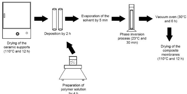
The membranes were prepared in triplicates by dip-coating, beginning with the deposition of the PA66 solution inside the tubular ceramic support. The PA66 solution was prepared at a concentration of 5% (w/v) using formic acid as solvent. The ceramic tube was closed on one side and the solution kept inside the tube for 2 hours. The excess solution was removed and the tube was immersed in water for 2 hours in order to form the selective polyamide layer through a phase inversion process. The composite membrane remained for 6 h at 30 °C in a vacuum oven to eliminate the excess solvent (Figure 1). This procedure was repeated to form membranes with two layers. The membranes with one and two layers were named PA-1 (ceramic support internally coated with one layer of PA66) and PA-2 (ceramic support internally coated with two layers of PA66).
2.3. Characterization of the membranes
2.3.1. Porosimetry by mercury intrusion
The average pore size was determined by analysis of mercury intrusion porosimetry. The analysis was performed in a porosimeter Autopore II/9220 Porosimeters (Micrometrics Instruments Corp.).
2.3.2. Scanning electron microscopy (SEM) analysis
The samples were initially fractured in liquid nitrogen and then gold-coated by sputtering for 1.5 min. The morphology of the surface and cross section of the membranes was obtained by scanning electron microscopy–SEM ZEISS-LEICA/400.
2.3.3. Pure water lux
The ultrailtration tests were performed in a bench system, as shown in Figure 2. System comprises a feed tank of 2 liters, a pumping system with a diaphragm pump with three chambers of the positive displacement motor and Permanent magnet, P/N 11-155-05. The working low rate used was 0.93 liters per minute with Reynolds number 2630.
Importantly, the system had two check valves, one after the gauge and the other at the beginning of bypass, which returns part of the low that is repressed by feeding back to the pump. The irst valve aimed to restrict the passage of the feed low and cause pressure loss to increase the transmembrane pressure; the second controlled the low in the system.
These characterization tests were performed with pure water for two hours, and each 10 min the permeate volume was measured. For these analysis were used three samples of each membrane and ceramic suport. The order of the pressures used were 300, 250, 200 and 150 kPa. The permeate lux was calculated according to Equation 1:
w1 V J
A t =
∆ (1)
where JW1 is the water lux (L∙m-2∙h-1), V is the permeated volume (L), A is the inner membrane area (0.0052 m2), and Δt is time of permeation (h).
2.3.4. Membrane Resistance (Rm)
The membrane resistance is the resistance offered by the membrane to the feed low. It is an indication of the osmotic limitation of the membrane due the transmembrane pressure. The membrane resistance was calculated using Equation 2:
m w w1 P R J η ∆ =
× (2)
where RM is the membrane resistance (m−1); ∆P is the transmembrane pressure (Pa); ηW is the viscosity of pure
water (8.4×10⁻⁴ Pa∙s).
2.3.5. Determination of protein rejection
The solutions of trypsin (20 kDa) – Merck / E. Merck darmstadt, Germany, egg albumin (45 kDa) and bovine serum albumin (BSA) (69 kDa) (Inlab/Alamar Tecno-Cientíica Ltda) were used to determine the rejection performance of the composite membrane. All the solutions were prepared at a concentration of 100 ppm. Protein rejection was measured by reading the absorbance on the wavelength of 280 nm using a Genesys Ultraviolet Spectrophotometer, 10UV, Termo Spectronic (UV-Visible). The retention (%RP) was calculated by Equation 3:
% p .
f C
RP 1 100
C
= −
(3)
where CP is the solute permeate concentration and CF is the solute feed concentration.
2.3.6. Pore statistic
The study of pore statistics was realized following the methodology described by Arthanareeswaran & Thanikaivelan13. In this study, average pore size, surface porosity and pore density of membranes were calculated based on protein rejection.
The radius of the solute that showed a retention (%RP) above 90% was used to measure the average pore size of the membranes and of the ceramic support (Equation 4).
% R 100 RP α =
(4)
Assuming the membrane to be asymmetric type, the surface porosity of the membrane as determined using Equation 5.
w w1
3 J
R P
πη ε =
× ∆ (5)
where ε is the surface porosity; ηW is the viscosity of the
deionized water (g∙cm-1∙s-1); J
W1 is the pure water lux (cm∙s
-1) and ∆P is the applied pressure (dyn∙cm-2). From the values of ε and R (cm), the pore density in the membrane surface as calculated using Equation 6.
2 n
R ε π =
× (6)
where n is number of pores∙cm-2.
2.3.7. Fouling-resistance ability
After 2 hours of permeation BSA solution, the membranes were washed with deionized water for 20 min. Pure water lux (JW2) of the cleaned membranes was measured at 200 kPa. The fouling-resistance ability of the composite membranes
was evaluated by the lux recovery ratio (FRR) calculated by the following Equation 713.
w2
w1 J
FRR 100
J
= × (7)
2.3.8. Cleaning chemistry in recovering the low
A solution of sodium hydroxide was used to make 100 ppm chemical cleaning of the ceramic backing and composite membranes PA-1 and PA-2. This process was performed at pressure of 100 kPa for 2 h at 45 °C. Afterward systems were washed with distilled water.
3. Results and Discussion
3.1. Characterization of ceramic support and
PA-1 and PA-2 membranes – pore diameter
and morfology
The pore diameter (mean), Figure 3, determined by mercury porosimetry, was 0.65 μm for the α-alumina support (Figure 3a) and 0.35 μm for PA-1 membrane, Figure 3b. PA-2 membrane showed a pore diameter between 0.18-0.56 μm, Figure 3c. The decrease in the diameter pore of the PA-1 and PA-2 in relation to that of ceramic support conirms effective interaction occurs between the substrate and the polymer producing a selective membrane for separating the solute lower molecular weights, the results are shown as permeation experiments.
The deposition of the second layer of PA66 was performed over the irst one. The insertion of this second layer, using the same procedure, led to a partial dissolution of the irst layer of polyamide 66. Thus, part of the polymer was adhered to the substrate (ceramic support) and the rest was bound to the polymer. Therefore, the existence of two pore distributions (0.18 and 0.56 µm) can be explained in terms of the heterogeneity of the formed membrane.
Figure 1. Experimental methodology used in obtaining of the composite membranes PA-1 and PA2.
Preparation and Characterization of PA66/Alumina Composite Membrane
2015; 18(4) 751
Tsetsekou et al. (2008)6 reported that increasing the amount of polymeric layers on ceramic support of alumina systematically lowers the porosity and the average pore size follows the same trend, although affected to a lesser degree. This can be explained by the difference in interfacial tension of the polymer solution when it is applied to a bare ceramic surface or on a surface already covered by a thin layer of polymer.
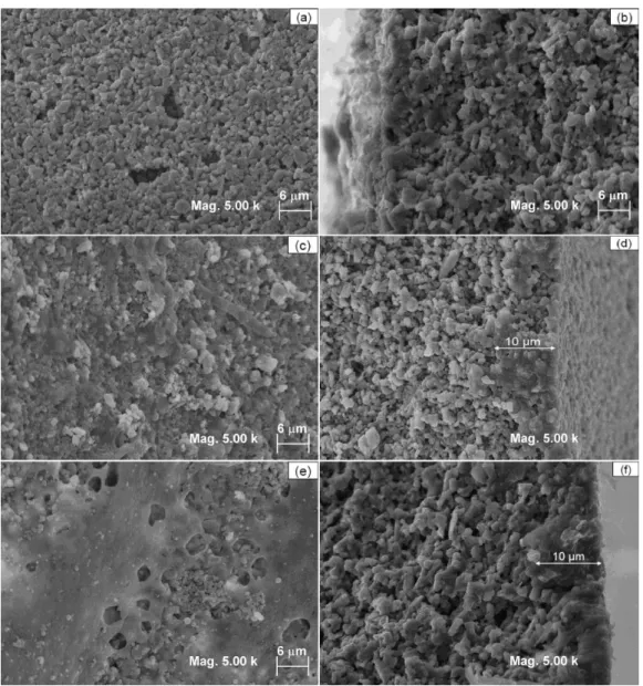
The presence of PA66 can be analyzed in Figure 4. There was a crack free coating on the support surface, which must have helped reduce the pore size, as shown in mercury porosimetry. The membrane cross-section was also deposited with PA66, which reached a depth of around 10 μm. The membranes PA-1 and PA-2 shows a dense ilm without macrovoids. There was no increase in top layer thickness (PA66) to PA-2 membrane as can be seen in Figure 4f.
3.2. Permeation experiment
3.2.1. Pure water lux
According to Wei et al., the structural stability of the composite membranes depends on good adhesion between the separation layer and the ceramic support14. Based on the permeability results discussed in this paper, the composite membrane was seen to present stable behavior during the tests.
Figure 5 shows the pure water lux of the ceramic support and the composite membrane. The ceramic support presented a higher water lux, as already expected. The top layer of PA 66 in the composite membrane caused the reduction of the pure water lux at 200 kPa from 65 to 18 L∙m-2∙h-1, which proves that polymer deposition on the surface of the ceramic support increased resistance to water lux.
Both membranes PA-1 and PA-2, with one and two layers by dip coating process, respectively, exhibited a very similar performance, where PA-1 membrane presented a slightly higher lux. The membrane resistance (Rm) was calculated and presented in Table 1. The ceramic support showed the lower membrane resistance of 0.83 x 10¹³ m-1. The composite membranes PA-1 and PA-2 presented higher membrane resistances, due to the polymer impregnation. As is observed in porosimetry analysis, the polymer impregnation decreases the pore size in the composite membranes.
3.2.2. Determination of molecular weight cut-off and rejection
The protein rejection of the composite membrane was determined using solutes with different molecular weight. Figure 6 shows the behavior of the composite membrane
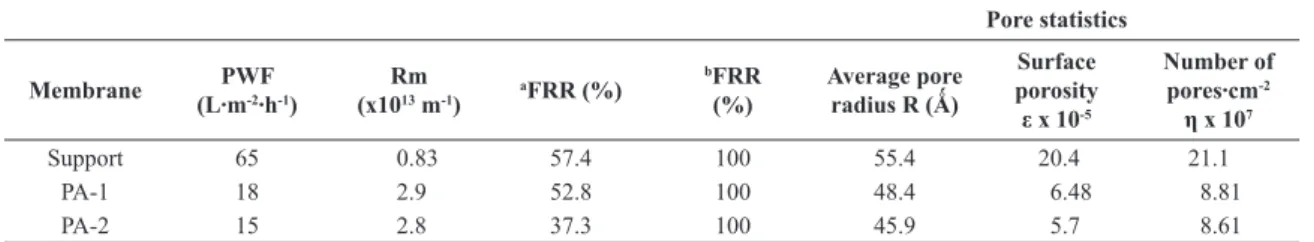
Table 1. Values of some characterization parameters of membranes.
Pore statistics
Membrane (L∙mPWF -2∙h-1)
Rm (x1013 m-1)
aFRR (%)
bFRR
(%)
Average pore radius R (Ǻ)
Surface porosity ε x 10-5
Number of pores∙cm-2
η x 107
Support 65 0.83 57.4 100 55.4 20.4 21.1
PA-1 18 2.9 52.8 100 48.4 6.48 8.81
PA-2 15 2.8 37.3 100 45.9 5.7 8.61
aTratament only with water. bTratament with solution of sodium hydroxide (1%).
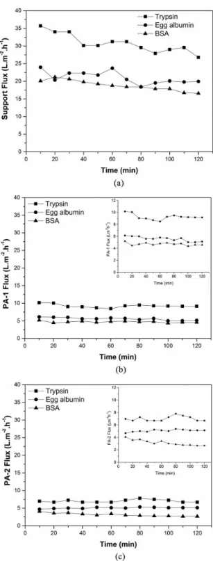
during the permeation test. Similar results demonstrated ceramic tube permeate lux obtained by Colle et al. (2007) in their experiments for oil retention for a pore size of approximately 0.5 µm15. The permeate lux decreased as the molecular weight of the solute increased, i.e., the smaller the molecular weight the more easily the molecule passes through the membrane. The order of intensity of lux decline was veriied for experiments with BSA > egg albumin > trypsin. This may be due to the decreasing molecular weights of BSA, egg albumin and trypsin which are 69, 45 and 20 kDa, respectively.
From permeate lux data, one can perceive average lux decrease and lux permeate decline during the iltration. The reason for a more intense decrease in average lux observed with the iltration of a protein solution with a higher weight can be interpreted based on total blockage of some
Figure 4. Micrographs obtained by SEM: (a) support surface, (b) support cross section, (c) surface of the membrane with one layer by dip coating process, (d) cross section of the membrane with one layer by dip coating process, (e) surface of the membrane with two layers by dip coating process and (f) cross section of the membrane with two layers by dip coating process.
Preparation and Characterization of PA66/Alumina Composite Membrane
2015; 18(4) 753
pores or due to an increase of a molecular layer of adsorbed protein on the inner surface of pores of membranes.
In Figure 7, protein rejection is shown as a function of the protein solute and membrane type. For both membranes, BSA was found to have higher rejection among the proteins studied. The support presented rejection of around 56 to 81% for trypsin and BSA, respectively. For PA-1 and PA-2 membranes, BSA rejection reached 93 and 98%, respectively.
Figure 7. The inluence of polymer deposition in protein rejection.
Figure 6. Protein permeate lux of the support (a) and composite
membranes PA-1 (b) and PA-2 (c).
Nandi et al.16 showed that the lux the membrane decreased and BSA rejection increased with an increase in both dip-coating time and cellulose acetate (CA) concentration. In three minutes of dipping time was observed rejection of 42% and 50% to 6 wt% and 8 wt% CA respectively. This ceramic composite membrane was found to be formed by blockage of ceramic support matrix (formation of intermediate layer) followed by deposition of CA over the support (formation of top layer). The increasing of the polyamide 66 layer on the ceramic support allowed a reduction in the pore size of the membranes obtained in this work. The thickness of the selective layer creates resistance to passage of the permeate lux and how much thicker the polymer layer larger the transmembrane pressure required in the separation processes6.
According Levänen et al.17, various physical phenomena occurring during dip coating. When dip-coating process was initiated, instantaneously CA solution tends to penetrate through the porous structure of support surface to yield an intermediate layer. This intermediate layer played an important role in membrane durability and bonding of the top layer with the ceramic support. The structural and morphological properties of the intermediate layer were largely dependent on the pore size and porosity of the support as well as concentration of CA used for dip coating. The growth of the CA top layer was anticipated after the formation of the intermediate layer. CA top layer growth rate was also largely dependent on the CA concentration in the solution, structure and morphology of the intermediate layer18,19. Thus, the increase of the polymer layer on the ceramic support is an important mechanism that inluences in the heterogeneity of selective layer and in the distribution of pore size.
3.2.3. Pore statistics
Based on the permeability experiment with the proteins, the mean pore radius could be determined as approximately 45 Å (4.5 nm), which is the size of the BSA molecule (Table 1). The pore size measured by the ultrailtration method is related to the high retention obtained by the polymeric top layer, which is the selective membrane layer.
Again, the polymer impregnation reduced signiicantly the surface porosity and the pore number.
The number of layers by dip coating process (one and two) presented a slight difference in pore statistical analysis. The same behavior showed in BSA rejection, where the rejection was above 90%.
Thus, the number of layers by dip coating process must be responsible for reducing the pore size, as well as the complete block of the micro-channels (pores) available for permeation. The effect of pore size reduction with polymer layers on the ceramic support can directly inluence membrane selectivity and determine the most appropriate separation processes15-20.
3.2.4. Flux recovery ratio (FRR)
In separation and puriication processes, the fouling is caused mainly by protein adsorption in membrane surface and membrane pore12. In this experiment, water was used to clean the membranes for 20 minutes. The FRR was 57.4 e 52.8% for support and PA-1 membrane, respectively. The PA-2 membrane presented a lower FRR, around 37.3%. After cleaning chemistry with sodium hydroxide (1%) was observed full recovery of the permeate lux for all membranes tested (100%), Table 1.
The cleaning with pure water was unable to remove the protein deposited on the surface and pores of the membrane.
That is, the recovery rate of permeate lux can be considered low, necessitating the use of appropriate cleaning procedures.
4. Conclusion
The ceramic support has pore size 0.68 µm. PA-1 membrane (one layer PA66) and PA-2 membrane (two layers of PA66) showed a pore diameter of 0.35 μm and between 0.18−0.56 μm, respectivamente. Membrane has a dense ilm of PA66 without macrovoids on the ceramic support.
The composite membranes presented stable behavior during the permeation tests, indicating that there was good adhesion between the polymer and the ceramic support. The reduction of the mean pore size and the permeate lux due to the incorporation of PA 66 increased the composite membrane selectivity.
The membrane with one layer by dip coating process (PA-1) was eficient, with over 90% rejection for BSA, with the advantage of higher permeate lux when compared with the membrane with two layers (PA-2). The permeation tests showed that the composite membrane can be applied in ultrailtration processes with MWCO of 69 kDa.
Acknowledgements
The authors would like to acknowledge the CNPq, CAPES for inancial support.
References
1. Maximous N, Nakhla G, Wong K and Wan W. Optimization of Al2O3/PES membranes for wastewater filtration. Separation and Purification Technology. 2010; 73(2):294-301. http:// dx.doi.org/10.1016/j.seppur.2010.04.016.
2. Zhang Y, Jin Z, Shan X, Sunarso J and Cui P. Preparation and characterization of phosphorylated Zr-doped hybrid silica/PSF composite membrane. Journal of Hazardous Materials. 2011; 186(1):390-395. http://dx.doi.org/10.1016/j.jhazmat.2010.11.016. PMid:21122987.
3. Khan MA, Kumar M and Alothman ZA. Preparation and characterization of organic–inorganic hybrid anion-exchange membranes for electrodialysis. Journal of Industrial and Engineering Chemistry. 2015; 21:723-730. http://dx.doi. org/10.1016/j.jiec.2014.04.002.
4. Ahmad J and Hägg M. Preparation and characterization of polyvinyl acetate/zeolite 4A mixed matrix membrane for gas separation. Journal of Membrane Science. 2013; 427:73-84. http://dx.doi.org/10.1016/j.memsci.2012.09.036.
5. Nataraj SK, Roy S, Patil MB, Nadagouda N, Rudzinski WE and Aminabhavi TM. Cellulose acetate-coated α-alumina
ceramic composite tubular membranes for wastewater treatment.
Desalination. 2011; 281:348-353. http://dx.doi.org/10.1016/j.
desal.2011.08.016.
6. Tsetsekou A, Arkas M, Kritikak A, Simonetis S and Tsiourvas D. Optimization of hybrid hyperbranched polymer/ceramic filters for the efficient absorption of polyaromatic hydrocarbons from water. Journal of Membrane Science. 2008; 311(1-2):128-135. http://dx.doi.org/10.1016/j.memsci.2007.12.017.
7. Dong Y, Lin B, Zhou J, Zhang X, Ling Y, Liu X, et al. Corrosion
resistance characterization of porous alumina membrane
supports. Materials Characterization. 2011; 62(4):409-418. http://dx.doi.org/10.1016/j.matchar.2011.01.012.
8. Li YS, Yan L, Xiang CB and Hong LJ. Treatment of oily
wastewater by organic–inorganic composite tubular ultrafiltration (UF) membranes. Desalination. 2006; 196(1-3):76-83. http:// dx.doi.org/10.1016/j.desal.2005.11.021.
9. Mittal P, Jana S and Mohanty K. Synthesis of low-cost hydrophilic ceramic–polymeric composite membrane for treatment of oily wastewater. Desalination. 2011; 282:54-62. http://dx.doi. org/10.1016/j.desal.2011.06.071.
10. Rosato DV and Dominick V. Reinforced plastics handbook. 3rd ed. New York: Elsevier Advanced Technology; 2004. 11. Lin D-J, Chang C-L, Lee C-K and Cheng L-P. Fine structure
and crystallinity of porous Nylon 66 membranes prepared by phase inversion in the water/formic acid/Nylon 66 system.
European Polymer Journal. 2006; 42(2):356-367. http://dx.doi. org/10.1016/j.eurpolymj.2005.07.007.
12. Basile A. Handbook of membrane reactors. Oxford: Woodhead Publishing Limited; 2013. Reactor Types and Industrial Applications 2.
13. Arthanareeswaran G and Thanikaivelan P. Fabrication of cellulose-zirconia hybrid membranes for ultrafiltration applications: performance, structure and fouling analysis. Separation and Purification Technology. 2010; 74(2):230-2355. http://dx.doi. org/10.1016/j.seppur.2010.06.010.
14. Wei W, Xia S, Liu G, Gu X, Jin W and Xu N. Interfacial adhesion between polymer separation layer and ceramic support for composite membrane, Materials. Interfaces and Eletrochemical
Phenomena. 2010; 56:1584-1592.
Preparation and Characterization of PA66/Alumina Composite Membrane
2015; 18(4) 755
chemically impregnated ceramic tubes. Journal of Membrane
Science. 2007; 289(1-2):58-66. http://dx.doi.org/10.1016/j.
memsci.2006.11.048.
16. Nandi BK, Uppaluri R and Purkait MK. Effects of dip coating
parameters on the morphology and transport properties of cellulose acetate–ceramic composite membranes. Journal of
Membrane Science. 2009; 330(1-2):246-258. http://dx.doi.
org/10.1016/j.memsci.2008.12.071.
17. Levänen E, Mäntylä T, Mikkola P and Rosenholm JB. Layer
buildup on two-layered porous substrate by dip-coating: modeling and effect of additives on growth rate. Journal of
Colloid and Interface Science. 2000; 230(1):186-194. http://
dx.doi.org/10.1006/jcis.2000.7018. PMid:10998304.
18. Song KM and Hong WH. Dehydration of ethanol and isopropanol using tubular type cellulose acetate membrane with ceramic support in pervaporation process. Journal of Membrane
Science. 1997; 123(1):27-33.
http://dx.doi.org/10.1016/S0376-7388(96)00198-6.
19. Ki Hong Y and Hong WH. Influence of ceramic support on pervaporation characteristics of IPA/water mixtures using PDMS/ceramic composite membrane. Journal of Membrane
Science. 1999; 159(1-2):29-39. http://dx.doi.org/10.1016/
S0376-7388(99)00050-2.