*e-mail: [email protected]
The Effect of Hot Multistage Drawing on Molecular Structure and Optical
Properties of Polyethylene Terephthalate Fibers
Aminoddin Hajia*, Ruhollah Semnani Rahbarb, Bahareh Kalantaric
aTextile Engineering Department, Birjand Branch, Islamic Azad University, Birjand, Iran
bDepartment of Textile and leather, Standard Research Institute, Karaj, Iran
cTextile Engineering Department, Amirkabir University of Technology, Tehran, Iran
Received: November 26, 2011; Revised: April 16, 2012
In this work, mechanical and structural parameters related to the optical properties of polyethylene terephthalate (PET) fibers drawn at hot multistage have been investigated. The changes in optical parameters upon changing draw ratio are used to obtain the mechanical orientation factors <P2(cos θ)> and <P4(cos θ)>, various orientation functions f2(θ), f4(θ) and f6(θ), and amorphous and
crystalline orientation functions (fa and fc). Also, the numbers of random links between the network
junction points (N1), the average optical orientation (Fav), and the distribution function of segment
ω(cos θ) were calculated. In addition, an empirical formula was suggested to correlate changes in the birefringence with the draw ratio and its constants were determined. The study demonstrated change on the molecular orientation functions and structural parameters upon hot multistage drawing. Significant variations in the characteristic properties of the drawn PET fibers were due to reorientation of the molecules caused by applied heat and external tension.
Keywords: polyethylene terephthalate, hot multistage drawing, orientation, mechanical and optical orientation functions
1. Introduction
Orientation in polymers can be produced by several processes, such as stretching of a molten polymer followed by rapid cooling of the melt and cold or hot drawing process. Altering the properties of synthetic polymer fibers by means of a drawing process is the result of changes in the molecular arrangement leading to a new polymeric structure. It is important to investigate the characteristic properties of drawn fibers and thereby the degree of orientation, crystallinity and other structural parameters and functions could be correlated to the fiber end-use.
PET is an extremely suitable polymer for detailed comparative studies of the molecular alignment because it is available in a number of a distinctly different physical state. The drawing behavior of PET has been studied extensively over many years and different workers have highlighted different features, from the purely mechanical aspects to the structural changes1-13. When PET fiber structure is
deformed by hot multistage drawing process, individual crystalline regions slide past each other, to take up a new position, where they are held together just as strong as in the origin material, owing to the formation of fresh, inter-atomic bonds. For this reason, the molecules pass from un-oriented state to the oriented state.
One of the most powerful experimental methods of short-range order determination in polymers utilizes birefringence. Birefringence is an important physical parameter that links the optical and mechanical properties of fiber. The examination of birefringence in conjunction with other physical measurements yields considerable
insight into the characteristic of the bulk polymer. If a polymer is subjected to an external force, such as drawing, the molecular chains become oriented along the drawing direction and oriented14,15.
In the present work, the optical parameters for hot multistage drawn PET fibers are utilized to calculate some structural parameters. Relationships between the obtained structural parameters are also given.
2. Material and Methods
2.1.
Preparation of samples
Low oriented PET yarn (LOY), 167 dtex, 34 filaments, was kindly supplied by Alyaf Co. (Iran). This yarn was melt-spun from PET chips with an IV of 0.65 dL.g–1. The
drawing was performed on an industrial Zinser draw-twisting machine (Germany), type 520-2. A three-step drawing process was carried out on the cylinders (godet roller) and hot plate by varying second-stage draw ratio. The different draw ratios of the drawn samples are shown in Table 1. The total draw ratio is calculated by multiplication of the draw ratios employed. The applied drawing conditions are listed in Table 2. These conditions were deduced from preliminary experiments.
2.2.
Birefringence measurement
Birefringence was measured on a Ziess polarizing microscope with a 30th order tilting compensator. The average
2.3.
X-ray analysis
The wide-angle X-ray diffraction (WAXD) data were collected using a bundle of PET multifilament yarn at a room temperature by using a EQUINOX 1000 X-ray diffractometer (Inel, France) equipped with a nickel-filtered copper Kα radiation (λ = 1.540 Å). The scattering intensities were recorded every 0.031° in the range of 2θ = 10-35°. The WAXD patterns were analyzed by a conventional curve-fitting procedure to obtain crystallinity value. For this purpose, the equatorial diffraction peaks were fitted into Pearson VII function and an empirical amorphous background was assumed to have Gaussian – type peak profile.
3. Theoretical Consideration
Hermans respected the orientation function f(θ) by a
series of spherical harmonics (Fourier series) as follows (Equation 1)16:
0
1
( ) ( )
2 n n
n
f ∞ n f f
=
θ = + < > θ
∑ (1)
where the odd components are all zero and the first three even components are given by:
2 2
1
( ) (3 cos 1)
2
f θ = θ − (1a)
4 2
4 1
( ) (35 cos 30 cos 3)
8
f θ = θ − θ + (1b)
6 4 2
6 1
( ) (231cos 15 cos 105 cos 5)
6
f θ = θ − θ + θ − (1c)
The parameters <fn> are the average values (amplitude).
In above equations, θ is the angle between the stretching direction and the chain axis17,18 and f is proportional to the
birefringence (∆n) as follows (Equation 2):
2
max
( ) n
f n
∆ θ =
∆ (2)
where ∆nmax is the maximum birefringence of fully oriented fiber. For PET, it has previously been determined to be 0.2419.
The optical orientation angle θ can be found using Hermans orientation factor from the following Equation:
1 1( (12 ( )) 2
3
Sin− f
θ = − θ (3)
where θ being the angle between the polymer chain and the fiber axis. Before orientation, the segments were randomly oriented at an angle θ with respect to the draw direction. After drawing, the segments will be constrained at an angle
β given by Equation 4:
3 2
tanβ =DR− tanθ (4)
On the aggregate model, the low-strain mechanical anisotropy is related to the orientation functions <P2(cos θ)> and <P4(cos θ)>. These functions provide some understanding of the mechanism of deformation. By considering the network as freely jointed chains of identical links called random links, <P2(cos θ)> is given by20
Equation 5:
2 1
2 2 3
2 2
1 2 3 cos
( )
2 1 (1 )
U U U
P
U U
−
+
〈 θ 〉 = −
− −
(5)
where U = D–3/2 and D is the draw ratio. Using the Treloar21
expression for the inverse Langvin function to obtain
4( )
P
〈 θ 〉, we have the following equation:
2 1
2 2 1
2 2
4
1
2 1
2 2
35 3 cos
1 2
(1 ) 2(1 )
1 ( )
8
30 cos
1 3
1 (1 )
U U U
U U P U U U U − − + − − − −
〈 θ 〉 =
− + − − (6)
The overall orientation22 F
av was calculated from
birefringence measurements on individual fibers. Optical birefringence gives the average of crystalline and amorphous orientation. Frequently, orientation means orientation of ordered phases. It should be noted that both crystalline and amorphous materials can exist in both oriented and un-oriented states. The average orientation Fav was calculated from the following Equation:
2 av c a n F n n ∆ =
∆ + ∆ (7)
where the denominator is composed of the intrinsic birefringence of both the crystalline and the amorphous regions.
The number of random links between the network junction points (N1) is obtained from the following Equation2:
Table 1. Applied draw ratios in different stages of a multistage
drawing process.
Sample 1st Stage
draw ratio
2nd Stage
draw ratio
3rd Stage
draw ratio
Total draw ratio
1 1.2 3 1.3 4.68
2 1.2 3.4 1.3 5.304
3 1.2 3.8 1.3 5.928
4 1.2 4 1.3 6.24
Table 2. The operating conditions in drawing experiments.
Temperature of feeding roller
(°C)
Temperature of first godet roller
(°C)
Temperature of hot plate
(°C)
Temperature of second godet roller
(°C)
Temperature of third godet roller (°C) Drawing speed (m/min) Intermingling jet pressure (bar) Spindle speed (rpm) Room
temperature 90 130 130
Room
2 1
2
1 ( )
5
D D
P
N
−
−
θ = (8)
where D is the draw ratio.
Roe and Krigbaum23 derived an expression for the
distribution function of segments at angle θ with respect to the draw ratio (Equation 9):
2 2 1
1
1 1
(cos ) (3 cos 1)( )
2 4N D D
−
ω θ = + θ − − (9)
In semicrystalline polymers, crystalline and amorphous orientations are present and, assuming that the total birefringence is the sum of the crystalline and amorphous birefringence, Stein and Norris24 have shown that
(Equation 10)
(1 )
c c a a
n Xf n X f n
∆ = ∆ + − ∆ (10)
where ∆n is the measured birefringence, X is the crystallinity (obtained here from XRD measurement), ∆nc and ∆na are
the intrinsic birefringence values of segments in the crystalline and non-crystalline regions, respectively. The intrinsic birefringence values for the crystalline and amorphous phases were assumed to be ∆ =nc 0.22 and ∆ =na 0.275, based on literature data25.
The Gaylord’s theoretical analysis26 of stress-induced
crystallization is in good agreement with various experimental data27,28. The crystalline orientation factor f
c was evaluated
by using the following Equation:
3
3
( 1)
( 2)
c
D f
D
− =
+ (11)
where D is draw ratio.
The amorphous orientation function fa was calculated by subtracting the crystalline orientation from the overall orientation as determined from birefringence.
4. Results and Discussion
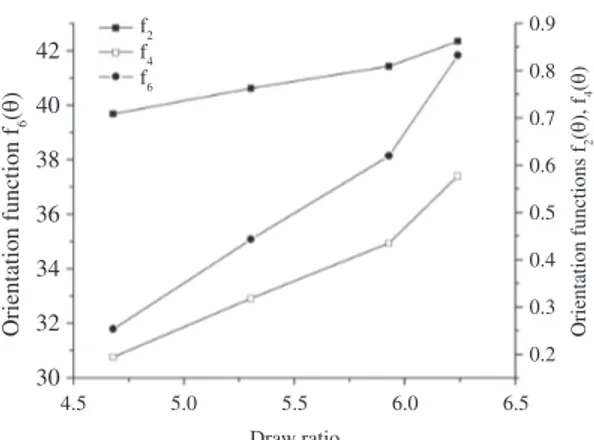
The optical orientation functions f2(θ), f4(θ) and f6(θ)
were calculated and their relationships with the draw ratio are given in Figure 1. Figure 2 shows the relationships between the orientation functions P2(θ) and P4(θ) and the
draw ratio. All the optical orientation functions increased as the draw ratio increased.
The calculated values for the orientation functions are useful in predicting the optical and mechanical anisotropy. The factors P2(θ) and P4(θ) are only mechanically dependent
and the values of P4(θ) are always comparatively small. The
relationships between the birefringence and the factors f2(θ), f4(θ) and f6(θ) are given in Figure 3. It shows a linear increase
in orientation function with increasing birefringence. This means that more orientation occurred involving molecular arrangements in both crystalline and amorphous regions.
Under a given external force, different material will show different states of deformation response. In this study it assumes that the polymer consists of aggregate of transversely isotropic units which have no extensibility themselves but are rotating in proportion to the macroscopic deformation of the sample. So, the mechanical anisotropy for PET fiber deformed upon hot multistage drawing, enables
the factors P2(θ) and P4(θ) to be calculated as a function of
draw ratio. The differences in values of P2(θ) and P4(θ) by
comparison with those for f2(θ) and f4(θ) can be attributed to
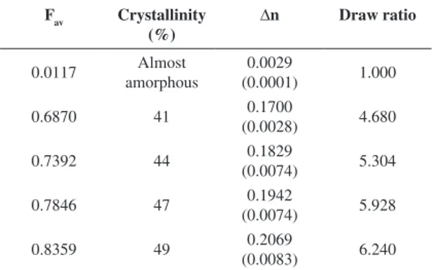
that the former factors are only functions of the draw ratio. Birefringence, crystallinity value (obtained by XRD) and average orientation function for PET samples are listed in Table 3. As can be seen in Table 3, drawing significantly increased the birefringence values of PET fibers, indicating
Figure 1. The optical orientation functions f2(θ), f4(θ) and f6(θ) as a function of the draw ratio.
Figure 2. The mechanical orientation functions P2(θ) and P4(θ) as a function of the draw ratio.
significantly improved overall molecular orientation. The increase in ∆n is a result of a large improvement in axial packing and slightly reduced molecular packing in the radial direction. In the hot drawing process, the temperature changes the molecular mobility due to input thermal energy and this decreases the resistance of the polymer network to deformation. Therefore, the efficiency of chain orientation during drawing of PET increases and gives rise to higher birefringence values. A greater alignment of chains should therefore gives rise to higher crystallinity, which can be found in the crystallinity values obtained by X-ray diffraction (see Table 3). Figure 4 shows equatorial WAXD scan of diffraction patterns of undrawn and drawn samples. X-ray diffraction pattern of undrawn PET fiber shows an almost amorphous behavior. The crystalline content of the undrawn sample is low and therefore it is not possible to detect by X-ray diffraction. In contrast, all the drawn samples show crystalline reflections and three reflection planes (010), (110), and (100) were recognized. Upon hot multistage drawing, an increase in crystallinity can be attributed to the orientation-induced crystallization as well as thermal-induced crystallization. With increasing
chain extension, fiber crystallization is promoted due to the decreased kinetic barrier29.
A c c o r d i n g t o t h e r e l a t i o n s h i p b e t w e e n birefringence-crystallinity, we can use orientation measurement to estimate the crystallinity values (X). Therefore, the graph was fitted linearly in Figure 5 and the following empirical formula was suggested for PET fiber drawn with different draw ratios ranging from 4.680 to 6.240:
221.4 3.5094
X= ∆ +n (12)
From the Equation 12, the initial value of crystallinity for undrawn fiber, which is corresponded to zero birefringence, was calculated to be 3.5%. This value is in good agreement with X-ray diffraction pattern of undrawn sample which shows an almost amorphous (Figure 4).
The number of random links between the network junction points (N1) increased with increasing draw ratio as shown in Figure 6. This can be attributed to the slippage in the network required by a transition from affine to pseudo-affine deformation. A value for N1 of about 5.466 for sample drawn at draw ratio of 4.680 is in reasonable agreement with previous reported value for a rubber like network (affine deformation)30. This
suggests that beyond the draw ratio of 4.680, the PET fiber deforms pseudo-affinely. Because the amorphous chains and crystallites are oriented toward the draw direction simultaneously, the pseudo-affine deformation is reasonable only when the molecular relaxation does not exceed the orientation. Also the distribution function of segment
ω(cos θ) is drawn as a function of draw ratio in Figure 6 and increases with an increase in draw ratio. Changes of ω(cos θ) give indication for mass distribution within PET fiber chains and new reorientations were given31. When a molecular
network is deformed unidirectionally, the distribution of chain displacement vectors becomes rather well oriented along the stretching direction. The relationships of tan θ and tan β values with draw ratio are given in Figure 7. As can be seen in Figure 7, both tangents decreased by increasing the draw ratio for hot multistage drawn PET fibers. Before orientation, the segments were randomly oriented at an angle
θ with respect to the draw direction. After the hot multistage drawing process, the segments will be constrained at angle β. The relation between the orientation angle before and after drawing was clarified by plotting the relation between the tangent of these angles and the draw ratio according to Equation 4.
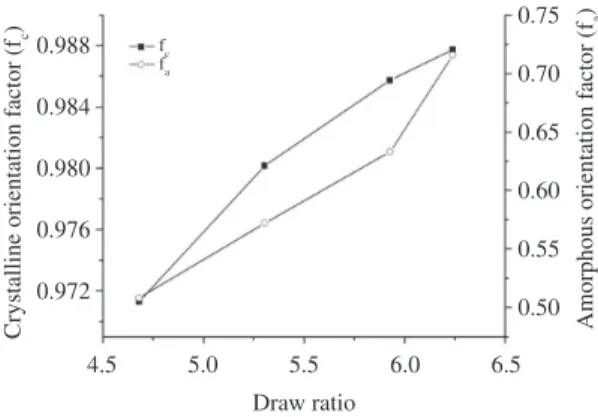
Figure 8 shows the relationships between the crystalline and amorphous orientation factors and draw ratio. As can be observed, both fa and fc were found to increase
with increasing draw ratio. The rapid development of the crystalline orientation factor to the almost full fiber-axis orientation compared with the slower development of orientation in the amorphous orientation and an intermediate increase in the average orientation function (Table 3) is common behaviors for flexible chain polymers32. Mobility
of chain segments and ability of orientation increase upon hot drawing gives rise to an increase in orientation factor. It is seen that fc is already quite high at all draw ratios, whereas fa develops slowly and increased more significantly with
increasing the draw ratio. This shows that more orientation
Table 3. Values of birefringence, crystallinity and average optical
orientation Fav for PET fibers in different draw ratios.
Fav Crystallinity
(%)
∆n Draw ratio
0.0117 amorphousAlmost (0.0001)0.0029 1.000
0.6870 41 (0.0028)0.1700 4.680
0.7392 44 (0.0074)0.1829 5.304
0.7846 47 (0.0074)0.1942 5.928
0.8359 49 (0.0083)0.2069 6.240
The numbers in parentheses are standard deviations.
orientation factor of the drawn sample is almost identical, the birefringence is affected mainly by the degree of chain alignment of the amorphous region.
The contribution of first-stage drawing to overall crystalline orientation factor is constant at all draw ratios due to the applied constant draw ratio at first stage of drawing (DR1 = 1.2). The second stage of three-stage drawing is more effective in developing the low orientation level of the crystallites formed in first stage and this contribution increases as total draw ratio increases. This occurs at the expense of decreasing in the contribution of third stage of drawing to overall crystalline orientation factor. The higher contribution of second step in final crystalline orientation factor is a result of the higher applied draw ratio in this stage (see Table 1).
From the well-known Mooney-Rivlin equation, the birefringence-strain relation is given as follows33
(Equation 13):
2 2
1
( )( A )
n D D A
D
−
∆ = − + (13)
A plot of 2
( )
n
D D−
∆
− against the reciprocal draw ratio
D–1 gives straight line whose slope A
2 and intercept with
ordinate A1 (Figure 9). The values obtained for A1 and A2 are
Figure 5. Birefringence versus crystallinity value obtained from X-ray diffraction for the drawn PET fibers.
Figure 6. Variation of the distribution function of segment ω(cos θ)
and the number of random links between entanglements N1 due to different draw ratios.
Figure 7. Variation of the tangent of the orientation angle θ and β
for hot multistage drawn PET fibers at different draw ratios.
occurred in amorphous phase as well as the crystallite redistribution of the crystalline region. According to Equation 11, for the draw ratio of DR > 3, fc values will be
larger than 0.9, in fair agreement with other results on the drawn PET filaments25. The birefringence of a crystalline
polymer is made up of contributions from the crystalline and amorphous regions. Assuming that the crystalline
Figure 9. Plot of ∆n/(D – D–2) versus D–1; ∆n and D are birefringence and draw ratio, respectively. See the text for details.
0.02245 and 0.06586, respectively. In general, the ratio A2/A1 is approximately similar to C2/C1 for the Mooney-Rivlin equation, so the birefringence remains proportional to the stress.
An empirical formula was suggested to evaluate the relationship between the birefringence and draw ratio as follows (Equation 14):
2 0.06586
( ) 0.02245
n D D
D
−
∆ = − + (14)
The advantage of this relation is that one can determine the birefringence at every draw ratio. Also, using this formula one can theoretically predict the preferable value of the draw ratio that is required for certain application.
5. Conclusion
Hot multistage drawing has been applied to observe the changes in the orientational behavior of PET polymer chains at a molecular level. The results of this study prove that in hot multistage drawing, external tension and applied heat have a significant effect on the optical and structural properties of the drawn fibers. The birefringence and orientation function increased linearly up to high draw ratio with increasing draw
ratio and this attributed to significant chain extension during multistage drawing with less chain relaxation upon applied heat. A mathematical correlation between birefringence and crystallinity has been obtained and formulated for PET fibers. The orientation functions given by the two methods, optical and mechanical, were suitable for predicting molecular orientation in PET fibers. Both values increased as the draw ratio increased. The mechanical method could be used for determining the orientation parameters with fair accuracy. The number of random links between entanglements and the distribution function of segments were found to increase with increasing draw ratio. As the draw ratio increased, both crystalline and amorphous orientation functions increased and the smaller orientation angle formed by parallel molecules within the fiber axis. An empirical formula was suggested to correlate the observed change in birefringence with draw ratio and its constants were determined as A1 = 0.02245 and A2 = 0.06586.
Acknowledgements
Authors would like to acknowledge Islamic Azad University, Birjand Branch for financial support of the project.
References
1. Reitsch F, Duckett RA and Ward IM. Tensile drawing behaviour of poly(ethylene terephthalate). Polymer. 1979; 20(9):1133-42.
http://dx.doi.org/10.1016/0032-3861(79)90306-9
2. Perena JM, Duckett RA and Ward IM. A study of the drawing behavior of poly(ethylene terephthalate). Journal of Applied Polymer Science. 1980; 25(7):1381-90. http://dx.doi.
org/10.1002/app.1980.070250712
3. Goschel U. Thermally stimulated structural changes in highly oriented glassy poly(ethylene terephthalate).
Po l y m e r. 1 9 9 6 ; 3 7 ( 1 8 ) : 4 0 4 9 - 5 9 . h t t p : / / d x . d o i .
org/10.1016/0032-3861(96)00249-2
4. Asano T, Calleja FJB, Flores A, Tanigaki M, Mina MF, Sawatari C et al. Crystallization of oriented amorphous poly(ethylene terephthalate) as revealed by X-ray diffraction and microhardness. Polymer. 1999; 40(23):6475-84. http:// dx.doi.org/10.1016/S0032-3861(98)00839-8
5. Radhakrishnan J and Kaito A. Structure formation during the isothermal crystallization of oriented amorphous poly(ethylene terephthalate). Polymer. 2001; 42(8), 3859-66. http://dx.doi. org/10.1016/S0032-3861(00)00754-0
6. Oultache AK, Kong XH, Pellerin C, Brisson J, Pezolet M and Prud’homme RE. Orientation and relaxation of orientation of amorphous poly(ethylene terephthalate).
Polymer. 2001; 42(21):9051-58. http://dx.doi.org/10.1016/
S0032-3861(01)00397-4
7. Keum JK, Kim J, Lee SM, Song HH, Son YK, Choi JI et al. Crystallization and transient mesophase structure in cold-drawn PET fibers. Macromolecules. 2003; 36(26):9873-78. http://
dx.doi.org/10.1021/ma034694i
8. Keum JK and Song HH. Thermal deformations of oriented noncrsytalline poly(ethylene terephthalate), fibers in the presence of mesophase structure. Polymer. 2005; 46(3):939-45.
http://dx.doi.org/10.1016/j.polymer.2004.12.004
9. Yamaguchi T, Kim K, Murata T, Koide M, Hitoosa S, Urakawa H et al. Initial stage of fiber structure development in the
continuous drawing of poly(ethylene terephthalate). Journal of Polymer Science Part B: Polymer Physics. 2008; 46(19):2126-42.
http://dx.doi.org/10.1002/polb.21546
10. Kim K-H, Murata T, Kang Y-A, Ohkoshi Y, Gotoh Y, Nagura M et al. Microsecond Analysis of Quasi-Smectic Fibrillar Structure in the Continuous Fiber Drawing of Poly(ethylene terephthalate). Macromolecules. 2011; 44(18):7378-84.
11. Todorov LV, Martins CI and Viana JC. Structural development of poly(ethylene terephthalate) during uniaxial stretching above the glass-transition temperature: Study of the statistical influence of the stretching variables. Journal of Applied Polymer Science. 2011; 120(3):1253-65. http://dx.doi. org/10.1002/app.33099
12. Todorov LV, Martins CI and Viana JC. Solid-state structural evolution of poly(ethylene terephthalate) during step uniaxial stretching from different initial morphologies: An in situ
wide angle x-ray scattering study. Journal of Applied Polymer Science. 2012; 124(1):470-483. http://dx.doi.org/10.1002/
app.34706
13. Rudolf A, Gersak J and Smole MS. The effect of heat treatment conditions using the drawing process on the properties of PET filament sewing thread. Textile Research Journal. 2012; 82(2):161-171. http://dx.doi.
org/10.1177/0040517511413318
14. Sperling LH. Introduction to physical polymer science. 2nd ed.
New York: Wiley; 1992. p. 161.
15. Williams DJ. Polymer science and engineering. London:
Prentice-Hall; 1971. p. 190.
16. Gedde UFW. Polymer physics. London: Chapman and
Hall; 1995. p. 214.
17. Lefebvre D, Jasse B and Monnerie L. Fourier transform infra-red study of uniaxially oriented poly(2,6-dimethyl 1,4-phenylene oxide)-atactic polystyrene blends. Polymer. 1981; 22(12):1616-20.
18. Lefebvre D, Jasse B and Monnerie L. Evaluation of the birefringence of uniaxially oriented poly(2,6-dimethyl 1,4-phenylene oxide)-atactic polystyrene blends. Polymer. 1982, 23(5):706-9.
http://dx.doi.org/10.1016/0032-3861(82)90055-6
19. Purvis J, Bower DI and Ward IM. Molecular orientation in PET studied by polarized Raman scattering.
Polymer. 1974; 14(8):398-400.
http://dx.doi.org/10.1016/0032-3861(73)90030-X
20. Stein RS. The orientation of polyethylene. Journal of Polymer Science. 1959; 34(127):709-720. http://dx.doi.org/10.1002/
pol.1959.1203412747
21. Treloar LRG. Physics of rubber elasticity. 2nd ed. London:
Oxford university Press; 1958.
22. Balcerzyk E, Kozlowski W, Wesolwska E and Lewaszkiewicz W. Intrinsic birefringence of nylon 6. Journal of Applied Polymer Science. 1981; 26(8):2573-2580. http://dx.doi.
org/10.1002/app.1981.070260807
23. Roe RJ and Krigbaum WR. Orientation distribution function of statistical segments in deformed polymer networks. Journal of Applied Physics. 1964; 35(7):2215-19. http://dx.doi.
org/10.1063/1.1702821
24. Stein RS and Norris FH. The x-ray diffraction, birefringence, and infrared dichroism of stretched polyethylene. Journal Polymer Science. 1956, 21(99):381-396. http://dx.doi.
org/10.1002/pol.1956.120219903
25. Dumbleton JH. The effect of oil and air annealing on the structure of drawn poly(ethylene terephthalate). Polymer. 1969; 10:539-42.
http://dx.doi.org/10.1016/0032-3861(69)90067-6
26. Gaylord RJ. Orientation of crystallites formed in stretched polymeric networks. Journal of Polymer Science: Polymer
Letters Edition. 1975; 13(6):337-340. http://dx.doi.org/10.1002/ pol.1975.130130604
27. Le Bourvellec G and Beautemps J. Stretching of PET films under constant load. II. Structural analysis. Journal of Applied Polymer Science. 1990; 39(2):329-339. http://dx.doi.
org/10.1002/app.1990.070390210
28. De Vries AJ, Bonnebat C and Beautemps J. Uni- and biaxial orientation of polymer films and sheets. Journal of Polymer Science: Polymer Symposia. 1977; 58(1):109-156. http://
dx.doi.org/10.1002/polc.5070580111
29. Keum JK, Jeon H-J, Song HH, Choi J-I and SonY-K. Orientation-induced crystallization of poly(ethylene terephthalate) fibers with controlled microstructure. Polymer. 2008; 49(22):4882-88.
http://dx.doi.org/10.1016/j.polymer.2008.08.050
30. Cunningham A, Ward IM, Willis HA and Zichy V. An infra-red spectroscopic study of molecular orientation and conformational changes in poly(ethylene terephthalate).
Polymer. 1974; 15(11):749-56.
http://dx.doi.org/10.1016/0032-3861(74)90028-7
31. Fouda I and Seisa E. The effect of stretching on monofilament polypropylene sutures. Journal of Polymer Research. 2008; 15(4):259-68. http://dx.doi.org/10.1007/ s10965-007-9166-y
32. Rossignol JM, Seguela R, Rietsch F and Dupuis-Lallemand J. Intrinsic amorphous birefringence of semi-crystalline polyethylene from combined birefringence and infrared dichroism measurements. Journal of Polymer Science Part C: Polymer Letters. 1989; 27(13):527-532. http://dx.doi.
org/10.1002/pol.1989.140271303