*e-mail: [email protected]
Received: 11 December 2013 / Accepted: 11 June 2014
Manufacture of custom-made cranial implants from DICOM
®images using 3D printing, CAD/CAM technology and incremental
sheet forming
Jovani Castelan*, Lirio Schaeffer, Anderson Daleffe, Daniel Fritzen, Vanessa Salvaro, Fábio Pinto da Silva
Abstract Introduction: This work aims to pre-operatively manufacture custom-made low-cost implants and physical models (‘biomodels’) of fractured skulls. The pre-operative manufacturing of biomodels and implants allows physicians to study and plan surgery with a greater possibility of achieving the expected result. Customization contributes to both the esthetic and functional outcome of the implant because it considers the anatomy of each patient, while the low cost allows a greater number of people to potentially benei t. Methods: From CT images of a fractured skull, a CAD model of the skull (biomodel) and a restorative implant were constructed digitally. The biomodel was then physically constructed with 3D Printing, and Incremental Sheet Forming (ISF) was used to manufacture the implant from a sheet of pure grade 2 titanium.Before cutting the implant’s i nal shape from a pre-formed sheet, heat treatment was performed to avoid deformations caused by residual stresses generated during the ISF process. Results: A comparison of the dimensions of the implant and its respective CAD biomodel revealed geometric discrepancies that can affect both functional and aesthetic efi ciency. Nevertheless, the i nal shape preserved symmetry between the right and left sides of the skull. Electron microscopy analysis did not indicate the presence of elements other than pure titanium. Conclusions: Dimensional variability can be decreased with changes in the manufacturing process (i.e., forming and cutting) and the heating ramp. Despite biomedical characteristics, there was no contamination of the implant by harmful chemical elements. 3D Printing was effective in making the biomodel, enabling pre-operative planning and improving physician-patient communication. Current results indicate that ISF is a process that can be used to obtain custom-made implants.
Keywords Implant, Biomodel, Incremental sheet forming, Titanium, 3D printing, Custom-made.
Introduction
In medicine, customization is the new paradigm
for this century, seeking to adapt to the specii c
requirements of each patient (Chulvi et al., 2007). The manufacture of custom medical devices (i.e., prostheses and implants) is an important medical
i eld. According to Sicoli and Mrad (2010), the design
and manufacture of orthotics, prosthetics and special
materials (OPSM) used in medical procedures (e.g.,
reconstructive surgery) represent up to 80% of a
hospital bill. Most (91.2%) of the implants are located in neurocranial and temporal regions (Eui nger et al.,
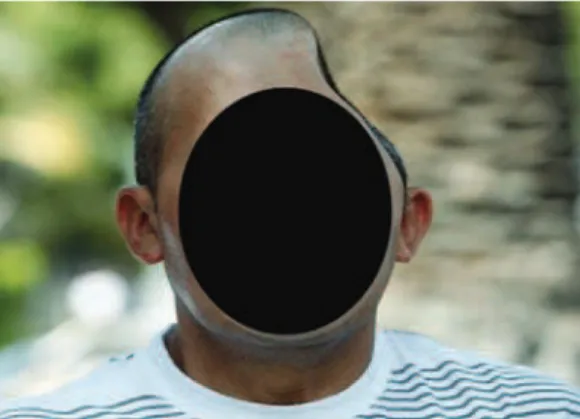
2006). Skull injuries can occur due to tumors, traumas caused by decompression surgery, infections, and fractures typically arising from automobile accidents or physical assault. When the affected area exceeds 60 cm2, it becomes necessary to use implants, as
the bone layer loses the ability to regenerate and reintegrate. Figure 1 shows a recent case of injury to
a skull: in 2010, Joseph (i ctitious name) from Los Angeles lost almost half of his skull in a bar i ght. The photo (from May 2013) shows an example of a
severe loss of bone tissue and brain mass. In cases
like this, autologous bone regeneration does not occur, requiring an alloplastic implant to provide the necessary protection to the remaining brain mass and to restore the esthetics of the individual.
Graphic workstations, CAD/CAM systems,
rapid prototyping and automated manufacturing processes for medical applications have been
developed and rei ned since the latter half of the 1990s (Wehmoller et al., 1995), although manual
processes currently remain (Goyal and Goyal, 2012). Hou et al. (2012), Lieger et al. (2010), Singare et al. (2004), Wei and Pallavi (2002) describe methodologies,
l owcharts and procedures for the reconstruction of
bone tissue using technological resources. These studies present the fabrication of implants using biocompatible polymers manufactured by different rapid prototyping processes (stereolithography, 3D Printing, selective laser sintering) as raw materials. However, pure grade 2 titanium exhibits the best long-term results, maintaining important features related to biocompatibility. Furthermore, according
grade 2 titanium are superior to those of polymers;
the elastic modulus is 4 to 5 times higher than that of
human bone and exhibits high corrosion resistance. The use of computer-aided design and advanced
manufacturing platforms provide a better it for the implant and better esthetic results (Mazzoli et al., 2009). Moreover, the use of these methodologies
and technologies confer the following advantages (Saldarriaga et al., 2011):
• Decrease surgical time by 85%;
• Restore the original appearance of the patient; • Reduce the possibility of errors during surgery; • Avoid modiications of the implant or the skull
region around the injury during surgery;
• Biomodels act as an effective communication
tool between neurosurgeons, patients and families when the surgical procedure is discussed.
Of the biocompatible materials used in reconstructive surgeries, according to TIG (Titanium…, 2013), titanium is widely used in bone tissue, joint and dental implants, cranio-maxillofacial reconstructions, cardiovascular devices (stents), temporary external
prostheses and surgical instrumentation. More
than 1,000 tons of titanium is implanted in patients
worldwide yearly. Mechanical requirements for joint
replacement increase with greater longevity. Bone can be worn down due to intense physical activity
or lost due to trafic accidents or physical assault.
Lightweight, strong and very biocompatible, titanium is one of the few materials that naturally match the requirements for implantation in the human body.
Methods
The development of implants is divided into seven steps:
• Biomodel computational modeling from DICOM images;
• Biomodel manufacturing by 3D Printing; • Implant modeling by CAD 3D software; • Implant manufacturing from a 0.5-mm titanium
sheet by Incremental Sheet Forming;
• Heat treatment of titanium sheet;
• Dimensional analysis between the reference
(CAD model) and titanium implant;
• Physical assembly of the implant and biomodel.
Step 1 – Biomodel computational modeling from DICOM images
The Digital Imaging and Communications in
Medicine (DICOM) electronic format is a set of
standards for imaging, storage and transmission of medical data, generating a common language between different equipment, devices and computers. These images are obtained from longitudinal sections of a damaged skull using Computed Tomography (CT)
scans. The conversion of DICOM to a 3D CAD vector ile (STL extension) is performed using InVesalius —
free software developed by the Center for Information Technology Renato Archer (Campinas, São Paulo,
Brazil) — that aids in diagnosis and surgical planning.
From CT images, the program creates virtual models
in 3D. A total of 724 DICOM images were processed
with a slice thickness of 0.3 mm to generate a digital solid object, visualized in Figure 2b (in green).
Step 2 – Biomodel manufacturing by 3D Printing
Medical applications of 3D Printing have included
the fabrication of replicas of broken bones and both broken bones and restorative alloplastic implants. Furthermore, 3D Printing is capable of creating models using several materials. Some examples include a) a model of a defective skull (Cui et al., 2014), b) a model of a defective skull with an implant, made with molding of poly-methyl-methacrylate (Goh et al., 2010; Rotaru et al., 2012); c) a model of a defective skull with an implant made with polyethylethylketone or laser melting thin layers of titanium powder (Klein et al., 2013) and d) a model of a defective skull with an implant made with acrylic (Werndle, 2012). Our work used 3D Printing technology to generate a physical model of a defective skull (see Figure 8) from thermoplastic aliphatic polyester (PLA), a renewable material derived from tapioca starch extracted from manioc (manihot esculenta),
a very common root in Brazil. However, despite its natural origin, there are no studies to ensure that PLA is a biocompatible material.
Step 3 – Implant modeling by CAD 3D software
The peripheral contours (i.e., the contour lines of the implant) were designed based on the perimeter of the fracture. In addition to the contour, other CAD guidelines were designed to serve as the skeleton of the
Figure 1. Severe cranial injury (NYDailyNews.com/us, December
implant surface based on the axial symmetry between the left and right sides of the skull. Figure 2a shows the digital model of the implant generated with an educationally licensed version of Solidworks software (Solidworks, CAD software developed by Dassault Systèmes S.A., Paris, France). Figure 2b shows the digital biomodel of a defective skull generated from CT images assembled with the implant model.
Step 4 – Implant manufacturing by Incremental Sheet Forming (ISF)
An alternative manufacturing processes was sought to avoid expensive manufacturing processes, such as milling, forging, conventional forming or multi-point forming (Chen et al., 2006; Tan et al., 2007). In addition, the manufacturing process had to be capable of producing custom models with simple tools. Incremental Sheet Forming (ISF) meets these requirements because it utilizes generic and low-cost tools and can be performed with machinery not
speciically designed for ISF, such as those at CNC
machining centers. This enables manufacturing of sheet metal parts for various geometries using the same tool;
CAD/CAM systems designed for machining can be
used to design the geometry and tool paths. Tools with
a generic proile (i.e. cylindrical or conical rod, with
a semi-spherical border) without a cutting edges, are
used to deform the sheet slowly in coordinated XYZ
movements (see Figure 3). These movements produce a plastic deformation located in a small region of the sheet. This region changes according to the tool’s movement and progressively causes deformation to occur, thus increasing the conformability of the sheet when compared with conventional forming processes
(Martins et al., 2008).
Incremental sheet forming with lower support (also known as Two-Point Incremental Forming, or TPIF) uses a polymer support located under the sheet in addition to the forming tool. This support, which
may be speciic or semi-speciic, is used to expand
the geometric range and improve the accuracy of the parts (i.e. the correspondence between the CAD biomodel and the manufactured part). The use of the lower support is particularly important for organic and asymmetrical geometries. Therefore, considering
Figure 2. Finished 3D CAD biomodel: a) Generating the implant model - to generate the surface, we used advanced computational modeling techniques; b) Digital assembly of the defective skull model and modeled implant.
Figure 3. Incremental forming with lower support. The tool performs downward movements according to the programming in the CAD/
that implants have precisely this type of geometry, TPIF is the ideal modality for their manufacture (Castelan, 2010).
The implant’s manufacture was planned using
EdgeCAM software, designed originally for the ield of mechanics and speciically for metal machining. However, in this study, it was used for three speciic
purposes: a) machining of the lower support (see Figure 3), forming the titanium sheet (Figure 4a) and
cutting the inal product (Figure 4b). Before sending the implant CAD ile (surface) to the CAM environment,
an extra forming region must be generated because
ISF starts on a lat and horizontal plane. As the implant
perimeter is irregular, it is necessary to create a region that joins this perimeter to a horizontal surface.
Having deined the 3D CAD biomodel, it is
possible to begin the manufacturing schedule step. On
the schedule are deined features, speeds and dynamic tool strategies. There are two schedules: the irst refers
to the lower support machining, which also serves to form the titanium sheet, and the second is used to cut the implant. Table 1 shows the technological data.
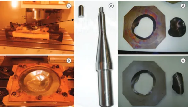
With simulations inalized, the programs were generated and transmitted to the CNC machine. The CNC Romi D 600 machine, originally intended for metal machining, has a robust coniguration for
serial production and intensive use in an industrial environment. A detail in Figure 4c shows the tool, composed of two parts: a rod (4340 steel, non-biomedical) and a tip (pure titanium grade 2). The
use of a titanium insert is justiied because AISI
alloy 4340 contains chemical elements harmful
to health (Mn, Si, Ni, and Cr). Another important
issue concerning the contamination of the sheet is the lubrication. Due to the characteristics of the ISF process where the tool slides over the sheet, friction is generated. The friction causes premature wear of the tool and the displacement of material from the
Figure 4. Incremental forming (a) and cutting (b) of a grade 2 pure titanium sheet; c) Tool shape made with 4340 steel and a tip made with
pure grade 2 titanium; d) Cut proile after heat treatment (stress relief) of the formed sheet; e) Cut proile without heat treatment – note the
drastic deformations due to internal stress.
Table 1. Manufacturing process.
Process Operation Tool
Feed speed (XY axis, mm/min)
Plunge Speed (Z axis, mm/min)
Rotation
(RPM) Strategy
Increment Z (mm)
Polymer machining
Rough End mill Ø10 4.000 2.000 3.000 Parallel 1.00
Finish ballnose
Ø8 2.000 2.000 4.000 Helical 0.10
Forming and cutting of sheet
Forming Special*
Ø10 1.500 1.500 50 Helical 0.10
Cut End mill 4 mm 1000 500 7000 Groove 1
sheet surface. Thus, lubrication is essential for sliding and to distribute the pressure of the tool on the sheet, preserving the integrity of both. Industrial mineral-based lubricants have excellent mechanical properties. However, their chemical components are harmful to
health (Zn, Pb, Ni, Cu), preventing their use in the
present work. Thus, it is necessary to use alternative inert lubricants, such as Vaseline, glycerin, propylene glycol, or an animal-based lubricant, such as swine grease (also known as lard, used in this work), which is widely used in the machining of screws and internal threads with excellent functional results.
Step 5 – Heat treatment of titanium sheet
Before cutting, it is necessary to perform a heat treatment for stress relief on the formed titanium sheet to avoid unwanted deformations (Göttmann et al., 2013). Figure 4e shows what happens in the absence of heat treatment; deformations are so large that it is unnecessary to compare the dimensions from the
reference model (CAD). Figure 4d shows a proile
cut from a thermally treated sheet. The heat treatment progressed as follows: heating for 2 h up to 400 °C, maintaining that temperature for 4 h and then cooling for 18 h to room temperature.
Step 6 – Dimensional analysis between the reference (CAD model) and titanium implant
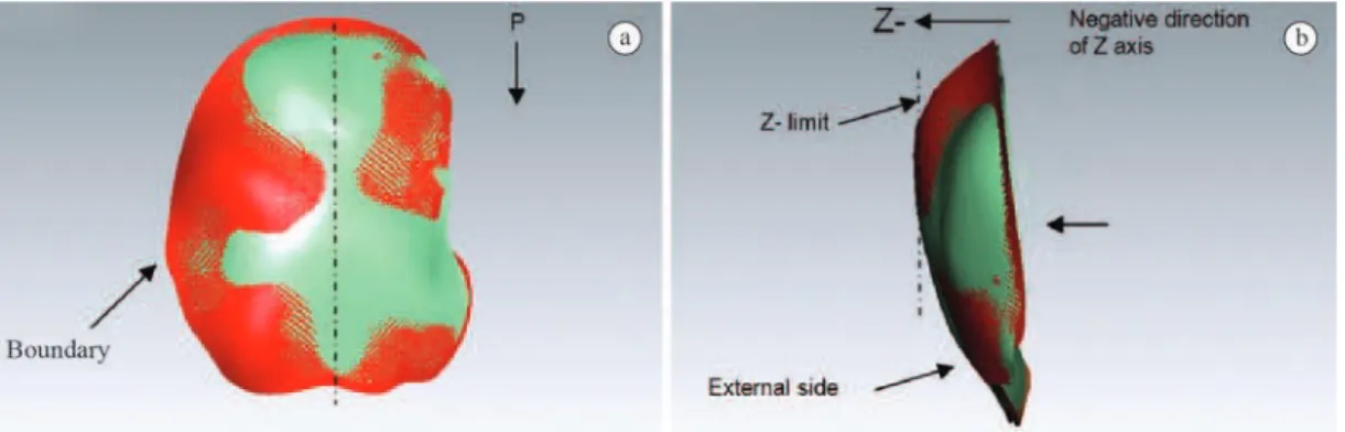
To evaluate the dimensional concordance between the CAD model and titanium implant, a 3D Scanner
(Material Selection and Design Laboratory, Federal
University of Rio Grande do Sul, Brazil) was used. The scanner ran a sweep along the titanium sheet, generating a CAD surface. This surface was assembled with the original CAD model of the implant, and its
dimensions were compared (see Figures 5 and 6).
Step 7 – Physical assembly implant-biomodel
Finally, the biomodel-implant physical assembly was performed (see Figure 7). This procedure can be useful to a physician to plan surgery, predict
movements, and evaluate the implant ixation and
explain to the patient and/or the patient’s family what will be performed during surgery.
Results
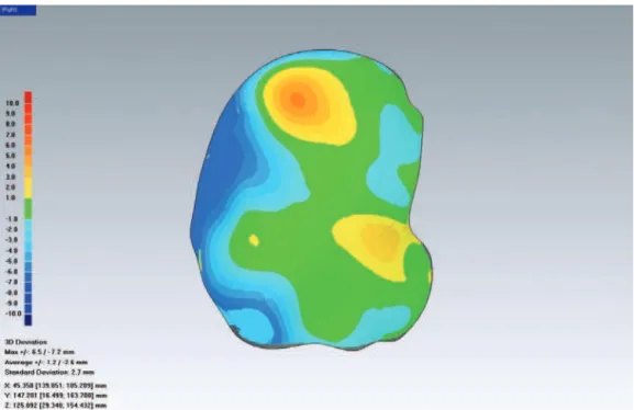
The analysis of dimensional discrepancies between the reference (CAD) model and manufactured implant
revealed values in the range of +6.5 mm to –7.2 mm
(Figure 6). The positive value indicates that in the
negative Z direction (see Figure 5b), the titanium
implant exceeded the respective CAD model; the negative value indicates that in the same direction, the titanium implant showed smaller dimensions than
the respective CAD model. In the irst case (positive
discrepancy), the unwanted deformation occurred due to the remaining stresses following heat treatment, indicating that this process needed to be adjusted (ramp, ultimate temperature or both) to minimize these stresses post-treatment to decrease this discrepancy. In the second case, the negative discrepancy occurred as a result of the cutting operation, which was completed
with an End Mill Ø4-mm tool (described in Table 1).
The tool’s rotation causes the deformation of the sheet, which was larger on one side than the other (see Figure 6, left side) due to concordant/discordant
tool rotation relative to the cutting proile. The ideal
solution would be laser-based cutting because the deformations would be smaller and more uniform, and
the surface inish of the cutting area (sheet thickness)
would be improved without the need for the manual polishing that was performed in this work. Indeed, the evaluated dimensional discrepancies indicate that the
process is eficient, but new studies and experiments
should be performed to improve results.
Another important characteristic is the maintenance of symmetry between healthy and recovered sides. Due to dimensional discrepancies, the symmetry was
Figure 5. Dimensional analysis between the CAD model (red) and scanned formed implant (green). a) Top view indicates that in the boundaries, the implant showed smaller dimensions in relation to the CAD model, while the implant’s external regions exceeded the CAD
affected (see Figure 7), although discreetly according to a visual analysis.
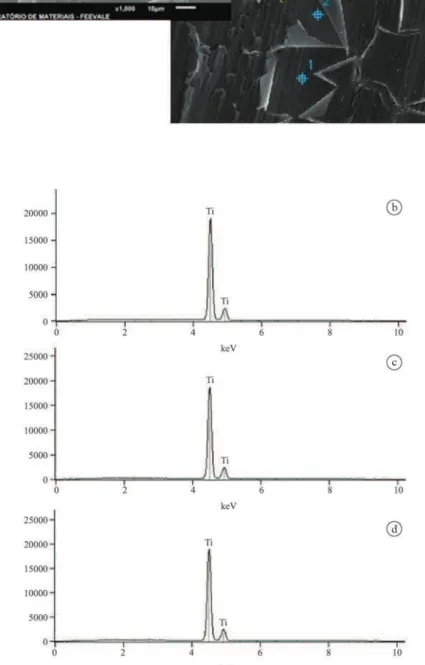
Furthermore, chemical analysis of the forming
titanium sheet was performed (see Figure 8). The EDS
analysis showed that there was no contamination by harmful elements and that cleaning and degreasing procedures were effective.
Discussion
The use of a lower support polymer with the speciic
format of the implant (TPIF) contributes to decreased dimensional discrepancies between the CAD model
and the formed implant. Previous experiments with Single Point Incremental Forming (SPIF) showed that this process is contraindicated for organic shapes. The heat treatment after forming is indispensable for maintaining the dimensional correlation with the CAD model. In this work, we applied TPIF and heat treatment to improve the dimensional aspects. However, the results remain unsatisfactory and there are ways to improve these results. Changes in the heat treatment parameters (ramp and ultimate temperature), forming parameters (feed and plunge
speed, tool movement strategy and Z-increment) and laser-based cutting proile can generate substantial
improvements in the dimensional aspects.
Figure 6. Dimensional analysis. The colors indicate the differences between the reference (CAD Model) and formed implant. There were
signiicant dimensional discrepancies in the left side (–7.2 mm) and in the upper region (+6.5 mm). The negative difference (i.e., where the
implant is less than the CAD model) was caused by the cutting tool (milling cutter); the positive difference (i.e., where the implant is greater than the CAD model) may have been caused by deformations that occurred during heat treatment.
Figure 8. Electron microscopy images (EDS analysis) of the forming titanium sheet did not indicate the presence of harmful chemical
Independent of the current results, this work presents two important contributions: a) the development of design procedures and manufacturing
planning by adapting existing resources (CAD/CAM mechanical software and CNC milling machinery)
and b) the reduction of production costs of implants.
According to neurosurgeon Dr. Sandro de Medeiros
(São José Hospital, Criciuma, Santa Catarina, Brazil), the cost of cranial implants manufactured in biocompatible polymer or titanium may reach
40-50,000.00 USD depending on the area, shape and
manufacturing process (molding vs. machining from a solid block). The costs of these method are estimated to be between 7-8,000.00 USD, which include a) the time spent making the CAD biomodels, b) the time
spent machining and programming (to control the XYZ movements of the CNC machine), c) the manufacture
of the titanium implant, d) the cost of the titanium sheet, and e) the cost of using the machining center’s machinery.
Other researchers have developed preoperative implant manufacturing systems. Bertol et al. (2010) conducted a study regarding the fabrication of custom implants, focusing on different alloplastic biomaterials (polymethylmethacrylate, titanium and calcium phosphate cements) and presented results similar to this study, although in that study, the implants were manufactured manually. In that case, the implant quality is dependent on the manual skill of the biomodeler. The purpose of this study was to develop a mechanized and parametric manufacturing system that could increase the possibility of producing implants with
esthetic-functional eficiency.
In Lieger et al. (2010), the methodology (based on CT images to manufacture biomodels and implants) is similar to this study’s, though it is different in two ways: a) the resources used (software and hardware) and b) the implant manufacturing process. Lieger used stereolithography to generate the implant, which is an expensive process mainly due to the cost of acquiring the equipment.
Alternatively, the use of computational resources allows for the early planning of surgery by means of visual analysis and the digital assembly of parts. The pre-visualization and the customized and mechanized manufacturing process contribute to the reduction of surgical time and minimize shape errors that may
affect the esthetic-functional eficiency of the implant.
Furthermore, the implant can be manufactured in a few hours.
The limitations of the study are related to the aseptic aspects of the environment used to perform the experiments, which is not suitable for the production of implants. The machinery, tools and other devices are
dispersed in an open academic room (manufacturing laboratory), presenting a high risk of contamination. Although there are procedures for cleaning, disinfecting and sterilizing implants, it is ideal to have a closed, aseptic environment with controlled temperature and
humidity and certiied by ANVISA for production
and utilization in humans.
Acknowledgments
The authors thank the National Council of Scientiic Development (CNPq) (project number 500882/2012), Dr. Sandro Medeiros (physician) for CT images
and providing information on the subject, Leonardo
Marasca Antonini for MEV and EDS analysis and
SATC University for machinery, resources, tooling and equipment.
References
Bertol LS, Escobar CF, Kindlein W Jr, Santos LA, Medeiros EB, Torriani MA, Bergmann CP. Projeto, fabricação e avaliação de implantes craniofaciais personalizados: proposta de utilização de materiais combinados. Revista Brasileira de Engenharia Biomédica. 2010; 26(2):79-89. http://dx.doi. org/10.4322/rbeb.2012.081
Castelan J. Estampagem incremental do titânio comercialmente puro para aplicação em em implante craniano [tese]. Porto Alegre: UFRGS; 2010.
Chen JJ, Liu W, Li MZ, Wang CT. Digital manufacture of titanium prosthesis for cranioplasty. The International Journal of Advanced Manufacturing Technology. 2006; 27(11-12):1148-52. http://dx.doi.org/10.1007/s00170-004-2309-y Chulvi V, Sancho A, Cebrian D, Jimenez R, Munoz C, Vidal R. Knowledge-based engineering in cranioplasty implant design. ICED 2007: Proceedings of the 16th International Conference in Engineering Design; Aug 28-31; Paris. Paris: Cité des Sciences et de L’industrie; 2007. p. 411-37. Cui J, Chen L, Guan X, Ye L, Wang H, Liu L. Surgical planning, three-dimensional model surgery and preshaped implants in treatment of bilateral craniomaxillofacial post-traumatic deformities. Journal of Oral and Maxillofacial Surgery. 2014; 72(6):1138.e1-4.
Euinger H, Weihe S, Scherer P, Rasche C, Wehmoller M. Management of cranial and craniofacial bone defects with prefabricated individual titanium implants: follow-up and evaluation of 166 patients with 169 titanium implants from 1994 to 2000. International Journal of Computer Assisted Radiology and Surgery. 2006; 1(4):197-203. http://dx.doi. org/10.1007/s11548-006-0054-4
case report. Journal of Indian Prosthodontic Society. 2014; 14(2):191-4. PMid:24757358. http://dx.doi.org/10.1007/ s13191-012-0185-y
Göttmann A, Korinth M, Schäfer V, Araghi BT, Bambach M, Hirt G. Manufacturing of individualized cranial implants using two points incremental sheet metal forming: future trends in production engineering. New York: Springer Berlin Heidelberg; 2013. PMCid:PMC3561303
Hou JS, Chen M, Pan CB, Wang M, Wang JG, Zhang B, Tao Q, Wang C, Hong-Zhang H. Application of CAD/CAM-assisted technique with surgical treatment in reconstruction of the mandible. Journal of Cranio-Maxillo-Facial Surgery. 2012; 40(8)e432-7. PMid:22484124. http://dx.doi.org/10.1016/j. jcms.2012.02.022
Klein GT, Lu Y, Wang MY. 3D Printing and neurosurgery: ready for prime time? World Neurosurgery. 2013; 80(3):228-35.
Lieger O, Richards R, Lui M, Lloyd T. Computer-assisted design and manufacture of implants in the late reconstruction of extensive orbital fractures. Archives of Facial Plastic Surgery. 2010; 12(3):186-91. PMid:20479435. http://dx.doi. org/10.1001/archfacial.2010.26
Martins PAF, Bay N, Skjoedt M, Silva MB. Theory of single point incremental forming. CIRP Annals - Manufacturing Technology. 2008; 57(1):247-52. http://dx.doi.org/10.1016/j. cirp.2008.03.047
Mazzoli A, Germani M, Rafaelli R. Direct fabrication through electron beam melting technology of custom cranial implants designed in a PHANToM-based haptic environment. Materials & Design. 2009; 30(8):3186-92. http://dx.doi.org/10.1016/j.matdes.2008.11.013
Rotaru H, Stan H, Florian IS, Schumacher R, Park YT, Kim SG, Chezan H, Balc N, Baciut M. Cranioplasty with custom-made implants: analyzing the cases of 10 patients. Journal of Oral and Maxillofacial Surgery. 2012; 70(2):e169-76. PMid:22260919. http://dx.doi.org/10.1016/j.joms.2011.09.036
Saldarriaga JFI, Velez SC, Posada AC, Henao BB, Valencia CAT. Design and manufacturing of a custom cranial implant. American Journal of Engineering and Applied Sciences. 2011; 4(1):169-74. http://dx.doi.org/10.3844/ajeassp.2011.169.174 Sicoli M, Mrad T. Oportunidades no mercado brasileiro de produtos e equipamentos médicos [internet]. Portal Farmacêutico; 2010 [cited 2010 Aug 30]. Available from: http://pfarma.com.br/noticia-setor-farmaceutico/varejo- farmaceutico/353-mercado-brasileiro-produtos-equipamentos-medicos.html.
Singare S, Dichen L, Bingheng L, Yanpu L, Zhenyu G, Yaxiong L. Design and fabrication of custom mandible titanium tray based on rapid prototyping. Medical Engineering & Physics. 2004; 26(8):671-6. PMid:15471695. http:// dx.doi.org/10.1016/j.medengphy.2004.06.001
Tan FX, Li MZ, Cai ZY. Research on the process of multi-point forming for the customized titanium alloy cranial prosthesis. Journal of Materials Processing Technology. 2007; 187-188:453-7. http://dx.doi.org/10.1016/j. jmatprotec.2006.11.149
Titanium Information Group - TIG. Titanium alloys in medical applications [internet]. Rotherham; 2013. [cited 2013 June 29]. Available from http://www.titaniuminfogroup.co.uk. Wang K. The use of titanium for medical applications in the USA. Materials Science and Engineering A. 1996; 213(1-2):134-7. http://dx.doi.org/10.1016/0921-5093(96)10243-4 Wehmoller M, Euinger H, Kruse D, Maßberg W. CAD by processing of computed tomography data and CAM of individual design process. International Journal of Oral and Maxillofacial Surgery. 1995; 24(1):90-7. http://dx.doi. org/10.1016/S0901-5027(05)80868-9
Wei S, Pallavi L. Recent development on computer aided tissue engineering: a review. Computer Methods and Programs in Biomedicine. 2002; 67(2):85-103. http://dx.doi. org/10.1016/S0169-2607(01)00116-X
Authors
Jovani Castelan*
SATC Faculty, Rua Pascoal Meller, 350, CEP 88805-380, Criciúma, SC, Brazil .
Lirio Schaeffer
Metal Forming Laboratory (Coordinator) – LdTM, Federal University of Rio Grande do Sul – UFRGS, Porto Alegre, RS, Brazil.
Anderson Daleffe, Daniel Fritzen, Vanessa Salvaro
Federal University of Rio Grande do Sul – UFRGS, Porto Alegre, RS, Brazil.
Fábio Pinto da Silva