American Journal of Engineering Research (AJER)
2015
American Journal of Engineering Research (AJER)
e-ISSN: 2320-0847 p-ISSN : 2320-0936
Volume-4, Issue-8, pp-170-178
www.ajer.org
Research Paper Open Access
Numerical simulation of the bulk forming processes for 1345
aluminum alloy billets
Fakhreddine. KHEROUF
1, Smail. BOUTABBA
2, Kamel. BEY
31LMI, Department of Mechanical Engineering, Badji Mokhtar University, BP 12, Annaba 23000, Algeria. 2Applied Mechanics Laboratory of New Materials, 8 May University, BP: 401. Guelma 2400, Algeria
ABSTRACT : This paper presents an improved numerical simulation of bulk metal forming processes. It takes
into the account the advanced formalism of large displacements and large deformations. Also, the interface workpiece formalism in considered. Metallographic studies are conducted to determine the evolution of the micro hardness as a function of annealing time and that to characterize accurately the plastic range of aluminum alloy for a range of plasticity 120%. The obtained results of metallographic studies are used to simulate a hot upsetting under the friction law of the plastic wave. Several simulations of forging operations of an axisymmetric billet by a rigid axisymmetric conical tool are performed with ABAQUS/standard computer code and that for preheated billets from 20 °C to 500 °C. The numerical study of the evolution of the normal stress at the interface has shown that the latter is independent of the tool roughness for a temperature close to 500 °C. The numerical study also allowed us to define the three areas of forging whatever cold; warm and hot forging. The effects of friction coefficient on the metal flow and contact pressure are numerically explored.Keywords
-Bulk forming, Finite elements, Roughness, Metallography, Plasticity
I.
INTRODUCTION
Forging is a bulk metal forming process which gives either a single geometric shape billet or a complex predetermined one and that by using a specific tools [1]. This process is widely used because the obtained parts have higher strength than ones obtained by machining or casting for equivalent masses.
These parts are resistive to strain and to impact resistance and that is due to metallurgical properties obtained during the bulk forming. Today, the automotive and aerospace industries are the predominant application because they use more than four-fifths of the produced parts by forging. Economic and technological interests of shaping metals are undeniable: high production rates, good geometric and mechanical quality, and low falls rate.
In the bulk forming processes, the friction plays an important role which is sometimes difficult to control. In the literature, several experimental tests are carried out to characterize the friction in plastic forming were reported [2].In the field of plastic forming, ring compression test is often used [3-6]. Also, a conventional test of a cylinder could be used to characterize the friction of the bulk forming operations [7-8]. The most sophisticated manufacturing processes have never produced perfect smooth surfaces. The characterization of the state roughness measurement plays major role in the study of friction.
In the present work this parameter (plastic flow) will be identified by a torsion test for which the plastic deformation zone is higher than in a tensile test. Thus, the torsion test was carried out on specimens of 1345 aluminum alloy to identify the law of the materiel flow. The identified parameter will be used into the simulation program. The studies on the state of specimens subjected to test upsetting showed a micrographic structure mainly characterized by large grains [17]. The annealing was performed on specimens before torsion tests in order to approximate this micro-structural state.
The simulation of the forging process is carried out by the FEM via the ABAQUS software using very fine mesh at the interface contact. The ABAQUS code offers the possibility to implement the plastic wave friction model using the user subroutine ".for". The main objective of this simulation is the comparison on the microscopic level of the sensitivity of the stress according to the temperature.
The paper is structured as follows: in section two, the theory of plastic wave friction is presented. The experimental procedure (hardness test, micrographic study, torsion test) is detailed in section three, the numerical simulation of the bulk forming processes is given in section four. The paper ends with concluding remarks and conclusion.
II.
S
UMMARY OF THE THEORYThe classical friction tests for bulk forming processes are usually based on simple compression by a rigid punch. This test induces a heterogeneous strain hardening in the billets [18].
A lot of microscopic models are developed in order to obtain a law of macroscopic friction [19-20]. The plastic wave model, formulated with slip line theory [21] and the upper bound, consider a plane strain field in a perfectly rigid plastic triangular asperity is based on a 2D geometry and actual roughness, of circular shape, is replaced by a triangular geometry of the same average height R and the same wavelength AR [22]. This model will allows to obtain a friction law at the interface according to normal contact stress, the roughness of the tool, the workpiece material yield stress and local constant friction coefficient. In this model, the friction force opposes the sliding of the rough surface and the resulting growth in the plastic wave material of the workpiece.
Table 1. Geometry of punch.
Cone Angle R (µm) AR (µm)
7° 20.985 359.060
III.
E
XPERIMENTAL DETAILS3.1. Hardness test
In this section the experimental tests are presented, cylindrical samples of 7 mm thickness and 20 mm diameter were cut from the heat-treated rods of the furnace at 320°C. A minimum of four readings were taken on each sample in order to obtain reasonable statistics for the measured hardness values.
3.1.1. Hardness before heat treatment
All hardness tests were carried out on the external faces [23] of the samples previously polished, under a consistent load of 300 kgf applied for about 15 seconds as shown in Table.2.
Table 2.Hardness before heat treatment.
Test1 Test2 Test3 Test4 Average
Vickers Hardness 40.1 40 42.6 41.1 40.95
3.1.2. Hardness after heat treatment
The annealing treatments of re-crystallization, which give new crystals, increase considerably the plasticity however, the elastic limit, the load rupture and the hardness are decreased.
To change the micro-structural properties, a thermal annealing is carried out on samples at 320 °C for a time period of 1 hour to 8 hours. After cooling, the hardness measurement tests are performed and the results are presented in Table 3.
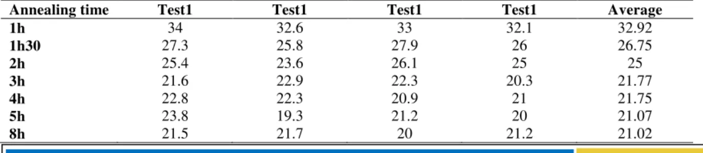
Table 3.Hardness after heat treatment.
Annealing time Test1 Test1 Test1 Test1 Average
1h 34 32.6 33 32.1 32.92
1h30 27.3 25.8 27.9 26 26.75
2h 25.4 23.6 26.1 25 25
3h 21.6 22.9 22.3 20.3 21.77
4h 22.8 22.3 20.9 21 21.75
5h 23.8 19.3 21.2 20 21.07
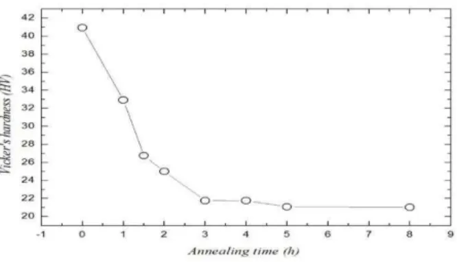
According to the obtained results, the hardness of the specimen drops significantly during the first three hours of annealing and then stabilizes at 21 HV (figure 1). One can deduce that it is necessary to have the same hardness as that obtained after upsetting test, to subject samples to annealing for a minimum time of at least 4 hours.
Fig. 1. Hardness evolution according annealing time.
3.2.
Micrographic study
To study the microstructure, the specimens were prepared to be in accordance with the standard metallographic procedure. Before performing the micrographic control specimens, polishing was performed using abrasive paper of finer silicon carbide, a finishing with Alumina is performed by a diamond paste to get fine surface. To bring out the grain boundaries and in order to obtain a contrast between different grains, a
chemical attack using appropriate Keller’s reactive (distilled water, hydrofluoric acid, nitric acid, hydrochloric
acid) was performed for 30 and 40 seconds. Metallographic microscope which is equipped with a camera connected to a PC to get shots of each samples.
3.3.
Evaluation of microstructure
In figure 2, analysis of shots is carried out and the following remarks can be made: For specimen without heat treatment, there are a few grains that are not clear. Annealing for 1 hour, no grain boundary is visible even by increasing the zoom. An annealing of 1h30 gives a lightly difference suppose an enlargement grains.
On this specimen, the grain boundary is visible. In the annealing of 2 hours and there is no exploitable visible change. Whereas, in the annealing of 3 hours, a significant difference compared to the other specimens is visible; grain boundaries begin to appear and we can easily identify the various grains on the figure e. Less grains are observed after 4 hours of annealing compared to one of 3 hours. After 5 hours of annealing, it is found that the microstructure of the specimen has completely changed. From figure h which corresponds to 8 hours of annealing, a significant increase is observed in grain size of specimen material. The latter is directly related to the annealing time. A great similarity is observed between the microcrystalline state micrograph of the specimen heated for 8 hours and the state of the specimen subjected to upsetting test.
3.4.
Mechanical characteristics and material
Numerical modeling of bulk forming processes (forging, stamping, punching ...) requires the prior determination of the mechanical characteristics of materials in the elastic range as well as those in large plastic deformations (100% to 300%). Accurate knowledge of those mechanical properties is usually required in various engineering applications such as aeronautical [24-25], automotive [26-27], naval [28-29] and in the mechanical manufacturing areas [30].
To determine the mechanical characteristics of the material, tensile test are used, from where the Young modulus and the Poisson's ratio of the material are measured. In [16], the tensile test is used and extrapolated the results to a larger plastic strain.
In this work, we performed a torsion test to determine the mechanical properties of the material for which we have a larger plastic strain. The specimens of 1345 Aluminum alloy with an initial diameter of 8 mm and an initial length of 160 mm, were subjected to a preliminary annealing at 320 °C for 8 hours . Then, the test torsion is performed. The stress-strain curve has been raised to 120% as given by figure 3.
Fig. 3. Stress-strain curve of the billet material.
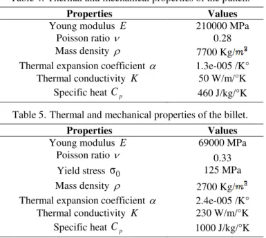
For the numerical modeling of the upsetting process, the punch material is supposed to be rigid with the combination of the following mechanical and thermal properties. See table 4. The billet is perfectly plastic material, the mechanical and thermal properties are shown in table 5.
Table 4.Thermal and mechanical properties of the punch.
Properties Values
Young modulus E 210000 MPa Poisson ratio 0.28 Mass density 7700 Kg/ Thermal expansion coefficient 1.3e-005 /K°
Thermal conductivity K 50 W/m/°K Specific heat
C
p 460 J/kg/°KTable 5.Thermal and mechanical properties of the billet.
Properties Values
Young modulus E 69000 MPa Poisson ratio
Yield stress
σ
00.33 125 MPa Mass density 2700 Kg/ Thermal expansion coefficient 2.4e-005 /K°
IV.
N
UMERICAL SIMULATION4.1.
4.2. Mesh and boundary conditions
The problem similarity allows considering calculation only for one half of the higher punch and a quarter of the billet. The geometries of the dies and billet are meshed with, 4-node axisymmetric thermally coupled quadrilateral elements with bilinear displacement and temperature shape functions, reduced integration, hourglass control. A mesh refinement is applied to the interface tool/workpiece (20 elements in front of each tool asperity). This simulation leads to 13875 elements for the mesh from the billet and 453 for the tool.
Fig. 4. Quadrilateral element.
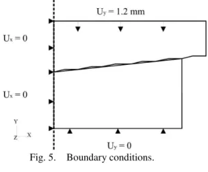
The billets are cylindrical with an initial diameter of 6 mm and an initial height of 8 mm, the top base is conical with angle inclination set to 7°. The interface is modeled with the assumption that the friction is not considered (perfect sliding) and the mesh is made very fine in the vicinity in the contact area. The punch goes down at a constant speed with a stroke of 1.2 mm subdivided in different positions. As for the boundary conditions, the transverse displacement is blocked on the level of the base as well as radial displacement on the symmetry axis. See figure 5.
Fig. 5. Boundary conditions.
V.
R
ESULTS AND DISCUSSIONS5.1. Contact pressure distribution
5.1.1 Effect of friction coefficient on contact pressure
Fig. 6. Effect of friction on the maximum contact pressure.
5.2. Plastic flow in the workpiece
The pressure distribution in the vicinity of the contact surface results in a plastic flow of the billet material. During the bulk forming process, the contact pressure in the upper region of the billet is much larger than that of the lower region, as shown in Fig. 7. By observing the directions shown on the figure it is observed that the diameter of the upper region is larger than that of the lower region of a deformed workpiece.
Fig. 7. Deformed workpiece for m0.=0.1
Accordance to the literature, we can evaluate quantitatively the plastic flow of a deformed slug with the following relationship:
max min
0
100%
D
D D
D
(1)
D is the diameter of the workpiece,Dmax and Dmin are the maximum and minimum diameters of the deformed surface of a workpiece, respectively.
Fig. 8. Effect of friction on the plastic flow.
Fig. 9. Workpiece diameter evolution.
Figure 9 shows the influence of friction on a diameter of the deformed workpiece, we find that the diameter increases with lower friction. In contrast to the larger diameter it decreases when the friction increases. In fact, the friction tool / workpiece interfaces not only affect the surface quality of the product but also changes in the geometry and physical properties. Experimental tests enable to validate the numeric simulation taking into account the friction at the interface.
5.3. Upsetting analyzes
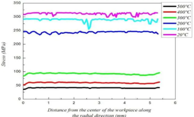
Some bulk forming processes are carried out at hot conditions to decrease the efforts, because the temperature determines the flow stress value of the material to be deformed. Figure 10 shows the predicted Von Mises stress distribution in workpiece surface during the simulation results history for various workpiece temperatures included between 20°C and 500°C. These results show that on the interface, more the temperature is high, less is important the stress
and its fluctuations: so, the material becomes easy to forge.Fig. 10. Von Mises stress distribution in workpiece surface along the radial direction.
Several of the billet preheat temperatures were studied in order to distinguish the various areas from the stress evolution during the upsetting process.
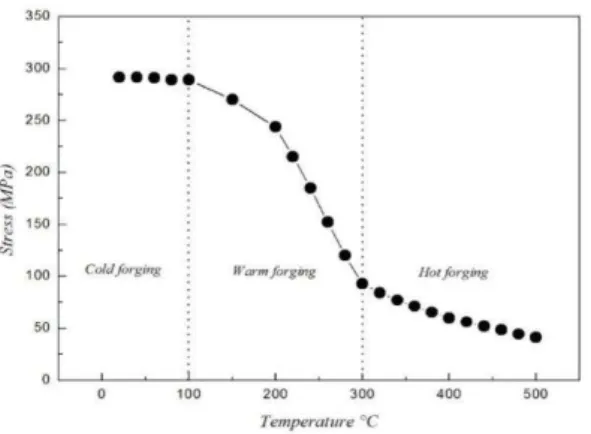
The numerical simulations were made for temperatures varying between 20°C and 500°C and that to locate the variation points, it can be found from figure 11 the yield stress evolution according to the billet pre heating temperature. On this Figure we notice three different zones:
Zone I: for temperatures going from 20°C to 100°C, the stress is practically constant, between 2.92E+02 MPa and 2.89E+02 MPa.
Zone II: change of the behavior is noted with a stress varying of 2.89E+02 MPa, for a pre-heating of 100°C, and with 9.28E+01 MPa for a temperature of 300°C.
Zone III: the stress is stabilized, for a zone of temperature of 200°C, between 9.28E+01 MPa and 4.12E+01 MPa.
Fig. 11. Yield stress evolution for aluminum alloy according to the temperature.
VI.
C
ONCLUSIONWe have presented in this paper, an improved numerical simulation of bulk metal forming processes. Our contribution concerns the precise characterization of materials in the deformation area. Torsion tests of specimens on Aluminum alloy were carried out to characterize material in the plastic range and micrographic tests were conducted on specimens subjected to annealing in order to obtain a metallographic state similar to that of specimens undergone a upsetting test. The obtained data were introduced into ABAQUS to simulate the behavior near the interface tool-workpiece in a bulk forming operation. In this simulation, the friction coefficient is modeled by so-called “plastic wave” friction law. The influence of the temperature on the metals bulk forming process was studied as well as the determination of the cold, warm and hot forging zones. It has been observed that roughness does not have any influence on the operations of hot bulk forming
R
EFERENCES[1] Felder, E. Procédés de mise en forme, Introduction, Techniques de l’Ingénieur, 2000.
[2] Zhang, Q.; Arentoft, M.; Bruschi, S.; Dubar, L.; Felder, E. Measurement of friction in a cold extrusion operation: Study by numerical simulation of four friction tests. Int J Mater Form, 1,2008, 1267-1270.
[3] Petersen, S.B.; Martins, P.A.F.; Bay, N. Friction in bulk metal forming: a general friction model vs. the law of constant friction.
Journal of Materials Processing Technology, 66,1997, 186-194.
[4] Joun, M.S.; Moon, H.G.; Choi, I.S.; Lee, M.C.; Jun, B.Y. Effects of the friction law on metal forming processes. Tribology International, 42,2009, 311-319.
[5] Hasan, S.; Jahan, R. On the measurement of friction coefficient utilizing the ring compression test. Tribology International, 32,1999, 327-335.
[6] Stembalski, M.; Pres´, P.; Skoczyn´ski, W. Determination of the friction coefficient as a function of sliding speed and normal pressure for steel C45 and steel 40HM. archives of civil and mechanical engineering,13 , 2013, 444 –448.
[7] Ebrahimi, R.;Najafizadeh, A. A new method for evaluation of friction in bulk metal forming. Journal of Materials Processing Technology, 152, 2004, 136-143.
[8] Tan, X. Comparisons of friction models in bulk metal forming. Tribology International, 35, 2002, 385-393.
[9] Tisza, M. Numerical modelling and simulation in sheet metal forging. Journal of Materials Processing Technology, 151,2004, 58-62.
[10] Weronski, W.; Gontarz, A.; Pater, Z. b.The reasons for structural defects arising in forgings of aluminiumolloysanalysed using the finite element method. Journal of Materials Processing Technology, 92-93,1999, 50-53.
[11] Xinghui, H.; Lin, H. 3D FE modeling of contact pressure response in cold rotary forging. Tribology International, 57,2013, 115- 123.
[12] Yaakoubi, M.; Kchaou, M.; Dammak, F. Simulation of thermomechanical and metallurgical behavior of steels by using ABAQUS software. Computational Materials Science, 68, 2013, 297-306.
[13] Rojek, J.; Onate, E.; Postek, E. Application of explicit FE codes to simulation of sheet and bulk metal forming processes. Journal of Materials Processing Technology, 80-81, 1998, 620-627.
[14] Cui, X. Y.; Li, G. Y. Metal forming analysis using the edge-based smoothed finite element method. Finite Elements in Analysis and Design, 63, 2013, 33-41.
[15] Baillet, L. Modélisation du frottement pour les opérations de matriçage, INSA-Lyon,1994.
[16] Vidal-Sallé, E. ;Boutabba, S. ; Cui, Y. ; Boyer, J. C. An improved « plastic wave » friction model for rough contact in axisymmetric modelling of bulk forming processes. Int. J. Mater. Form, 1, 2008, 1263-1266.
[17] Morival, S.; Boyer, J. C. Endommagement ductile des surfaces de produits forgés, rapport de PFE, INSA-Lyon, 2010. [18] Vidal-Sallé, E.; Maisonnette-Masson, S.; Boyer, J. C.About the validity of the plastic wave model for an actual roughness of
axisymmetric tooling in bulk forming. Int J Mater Form, 2, 2009, 217-220.
[19] Hélénon, F.; Vidal Sallé, E.; Boyer, J. C.Lubricant flow between rough surfaces during closed-die forging. Journal of Materials Processing Technology, 154, 2004, 707-713.
[20] Challen, J. M.; Oxley, P. L. B. Anexpiation of the different regimes of friction and wear using asperity deformation models.
[21] Vidal-Salle, E.; Dubois, A.; Dubar, M.; Dubar, L.; Boyer, J. C. Experimental identification and validation of the plastic wave approach in hot forging of steels. Wear, 286-287, 2012, 35-44.
[22] Kherouf F, Boutabba S, Bey K, Chettah A and. Boyer J.-C., Mesoscopic comparison of interface tool/workpiece for simulation by FEM of EN AW 1350 bulk forming alloy. Mechanics & Industry; 3 (16), 2015, 309.
[23] Shittu, M. D., Ibitoye, S. A., Olawale, J. O.Mechanical properties of cast hypoeutectic Al-Si alloy in hexachloroethane-coated mould. Journal of Engineering Science and Technology, 7, 2012, 529-539.
[24] Karagiozova, D.; Mines, R. Impact of aircraft rubber tyre fragments on aluminium alloy plates: II-numerical simulation using LS-DYNA. International Journal of Impact Engineering, 34, 2007, 647-667.
[25] Varas, D.; Zaera, R.; López-Puente, J.Numerical modelling of the hydrodynamic ram phenomenon. International Journal of Impact Engineering, 36, 2009, 363-374.
[26] Rusinek, A.; Zaera, R.;Forquin, P.; Klepaczko, J.R. Effect of plastic deformation and boundary conditions combined with elastic wave propagation on the collapse site of a crash box. Thin-Walled Structures, 46, 2008, 1143-1163.
[27] Kazanci, Z.; Bathe, K. Crushing and crashing of tubes with implicit time integration. International Journal of Impact Engineering, 42, 2012, 80-88.
[28] Zong, Z.; Zhao, Y.; Li, H. A numerical study of whole ship structural damage resulting from close-in underwater explosion shock. Marine Structures, 31, 2013,24-43.
[29] Ehlers, S. The influence of the material relation on the accuracy of collision simulations. Marine Structures, 23, 2010, 462-474. [30] Hui, W.; Ying-bing, L.; Friedman, P.; Ming-he, C.; Lin, G. Warm forming behavior of high strength aluminum alloy AA7075.