Veselin B. Batalović, Dušan Š. Danilović, Marija A. Živković
University of Belgrade, Faculty of Mining and Geology, Belgrade, Serbia
Abstract
Natural gas has become a global commodity in the energy consumption. New techno-logies, like as gas-to-liquid conversion technology, contribute to this. But more than 16% of the currently known global gas reserves cannot be produced, because they are heavily contaminated by CO2 and/or H2S: (CO2 > 10% and H2S > 5%). The traditional technology of amine treatment is not capable to economically remove these contaminants. The objective of this article is to investigate the possibilities of centrifugal separation in a way to resolve the existing problem. After analyzing the existing situation, in the centrifugal separation of natural gas, some innovations in separators' design and theory are suggested. The aim of the presented theoretical considerations is that the complex theory of separation should be adjusted to the needs of engineers engaged in design, development and operation of these devices.
Keywords: gas, calorific value, liquid, separation, efficiency.
SCIENTIFIC PAPER
UDC 662.767:66.071.6
Hem. Ind. 68 (2) 139–148 (2014)
doi: 10.2298/HEMIND120910035B
Available online at the Journal website: http://www.ache.org.rs/HI/
Natural gas, used by consumers, is almost entirely composed of methane. Natural gas, extracted from gas deposits, composed primarily of methane, is by no means pure. Impurities, that can occur in natural gas, are [1–5]: particles of rock material; liquid (water and crude oil); gases (carbon dioxide, hydrogen sulfide, oxi-des of nitrogen, etc.).
Fields with a high purity of methane (CH4) are
com-monly referred to as “sweet gas fields”. Fields that contain significant amount of hydrogen sulfide (H2S)
are called “sour” gas fields.
Fields that are contaminated with significant amounts of acidic gases, e.g., carbon dioxide (CO2) or hydrogen
sulfide (H2S), are called “acid” gas fields.
Removal of impurities: solid, liquid and gaseous, increases the possibility of gas exploitation at the gas fields, increases the heating value of gas, makes trans-port easier, protects the machine from corrosion, wear,
Correspondence: V.B. Batalović, Faculty of Mining and Geology,
Đušina 7, 11000 Belgrade, Serbia. E-mail: [email protected] Paper received: 10 September, 2012 Paper accepted: 16 May, 2013
etc. The cleaning process of natural gas can be divided into two technology related phases:
1. Primary cleaning of solid and liquid contami-nants;
2. Secondary cleaning of gaseous impurities. Particulate removal devices operate basically on the principle that a gas stream, containing particles, is passed through a region where the particles are acted on by external forces (gravitational or centrifugal) thereby separating them from the gas stream. This technology is well known and in this paper will not be represented.
When gas analyzed gas with high contents of gase-ous pollutants (Tables 1 and 2), [6–9] the traditional technologies of treatments are not able to economic-ally remove these pollutants. Finding the optimal solu-tion, for cleaning such polluted gases, is important task of modern science.
Centrifugal separation is one of solutions for gas cleaning. There are three methods of gas separation by centrifugation [2–4]:
Table 1. Acid natural gas volumetric composition [6]
Field Gas
CH4 C2H6 C3H8 C4H8 C4H10 CnHm N2 CO2
Srbobran 75.15 1.95 0.50 0.12 0.25 0.16 11.90 10.00
Miloševo 28.76 0.65 0.41 0.19 – – 6.94 63.05
Bečej 1 9.30 – – – – – 6.70 84.00
Bečej 2 65.74 0.09 – – – – 2.32 31.50
1. Gas/gas separation in a rotating cylinder based on the difference in molecular weight of the gaseous components;
2. Gas centrifugation with wall condensation; 3. Centrifugal separation of condensed contam-inant.
The particular interest in this paper is the con-densed contaminant centrifugal separation (C3-sep). C3-Sep process has two steps [2–4]:
1. Cooling the gas to a temperature whereby the gaseous contaminant becomes liquid in the form of a mist of micron-sized droplets;
2. Separating the mist from the gas by the rota-tional particle separator (RPS).
The concept (C3-Sep) is particularly suited for the application of CO2 and H2S removal from natural gas. It
has the potential to boost recoverable gas reserves by amounts which are energetically equivalent to multi-billions of barrels of oil.
C3-Separation splits the mixture into two phases: a liquid phase which is enriched in CO2 and a gaseous
phase that is enriched in methane CH4. The liquid phase
forms a mist of micron-sized particles. Centrifugal sepa-ration can rapidly remove the micron size particles using a rotating particle separator (RPS).
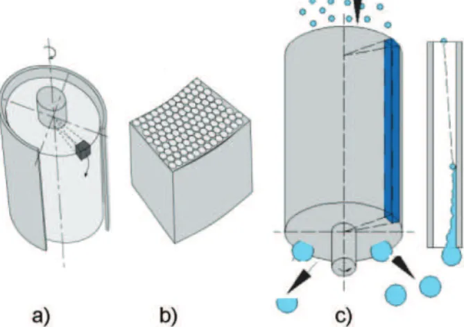
The core of the separator is the RPS element, i.e., a rotating cylindrical body which consists of a multitude of axially oriented channels, Figure 1a and b [2]. The diameter of the channels is typically 1–2 mm, its length is 0.2–0.5 m. The element is about 0.4–1 m in diameter. After entering the channels of the rotating body, liquid
mist particles, entrained in the gas, are rejected towards the collecting walls, Figure 1c. They then form a liquid film flowing downwards parallel with the gas.
At the exit of the channels, the liquid film breaks up into droplets of 50–100 μm in diameter.
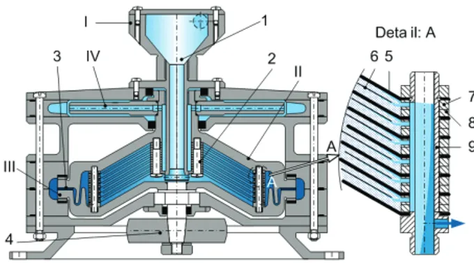
These droplets are rejected to the casing wall and subsequently leave the device via a liquid drain, Figure 2 [2].
Figure 2. Rotation particle separator (RPS).
This technical solution, apart from the numerous advantages (such as its simple construction), has cer-tain weaknesses:
- The separated liquid is accumulated, under the influence of the centrifugal force, on the tubes’ wall. Flow, of liquid gas, goes through the axial canals whose axis is the same as the rotation axis. The only source of energy for liquid flow is the gas drag force at the contact of liquid-gas fraction.
- At the tube’s exit the liquid suddenly turns (under the influence of the centrifugal force) in radius direction, which, in case of the sharp edges of the tube’s ends, can lead to cavitation i.e. part of the liquid fraction, due to the local pressure drop, can evaporate. - The separation process, of the liquid component from the gas component, is not equal for all tubes, since the influential centrifugal forces depend on the rotation radius, i.e., on the position of the tube in the separator’s construction.
- The drops of liquid, exiting the tubes that are closer to the axis of rotation, must cover a long way until they reach the inner wall of the separator body. Along that way they are exposed to the influence of pure gas stream. A significant problem, which accom-panies such manner of discharge, the friction of liquid drops against the gas stream, results in micro-heating at the drop’s surface, which can to spoil the quality of cleaning.
Table 2. Biogas composition [6]
Biogas CH4 (%) CO2 (%) O2 (%) N2 (%) H2S (ppm) Benzene (mg/m3) Toluene (mg/m3)
Deposit I 47–57 37–41 <1 <1–17 36–115 0.6–2.3 1.7–5.1
Anaerobic digesters I 61–65 36–38 <1 <2 – 0.1–0.3 2.8–11.8
Biogas 55–58 37–38 <1 <1–2 32–169 0.7–1.3 0.2–0.7
Analyzing the observed disadvantages, as well as numerous existing problems [2–4,10] the authors sug-gested a technical solution of the separator which, in their opinion could be a step forward in the techno-logical process of cleaning the natural gas, biogas and a number of other gases.
NEW TECHNICAL SOLUTION
The basic idea of a new technical solution is that the primary (removal of fine solid particles and small par-ticles of frosty water) and secondary (removal of pol-lutant, liquid phase which is enriched in CO2 and H2S)
separation will be made in one step. The prototype of the centrifugal separator was based on existing tech-nical solutions-disk stack centrifuges [11–13], with a number of innovations that are protected by patent applications [14,15]. One technical solution has been done and tested on tasks of solid–liquid mixture treat-ment. The results confirmed the initial assumptions in the design of the separator [16].
The prototype, Figure 3, consists the following sec-tions: product feed device with vortex tube (I), rotor (II) with disk stack insert, pump (III) and centrifugal com-pressor (IV). Motor with frequent regulator, ancillaries system and measuring equipment are also involved.
Figure 3. Centrifugal separator – prototype. 1. Vortex tube, 2. rotor; 3. pump; 4. compressor.
The lower half of the rotor, with disk stack insert (2), is connected to the motor via the belt drive (4). The disks split the working space into thinner segments in which the separation process is developing easier because the path of the heavier particles to the inner surface of disk is short.
Also, one of the observed disadvantages of the previous solutions [5] is the grip of the liquid fraction by the gas flow.
In new solution of separator such problem was removed by rings (7) (Detail A, Figure 3). The rings have the function of taking over the liquid that is drained through the inner surface of the disks (5) and liquid is directed towards the drainage tubes (9), i.e., to the rotor bottom.
Introducing the rings (8) will increase the gap between the discs (5). It is necessary, that the process of separation is done in optimal conditions, by impos-ing additional discs (6), smaller in diameter. The size of the gap (the thickness) is vital for the capacity and the quality of separation and it is theoretically defined, and experimentally verified. The goal of this innovation was made to further improve the efficiency of separation. Why this innovation?
The technical solution presented in the paper [16] is designed for the separation of solid-liquid mixture. Discs have the radial edge. The relationship of acceler-ation is: g/ω2 << 1, so that the output path of solid particles is strictly radial. As the velocity (vertical com-ponent) in the free space of rotor is too small, the direction of the particles remains radial. This solution is sufficient for good separation of solid-liquid mixture.
If the same construction of discs is used for the separation of gas–liquid mixture, the layer of liquid, after impact with the disc edge, would be again dis-persed into tiny droplets.
Micro-droplets would be drawn into the gas and re-introduced into the separation process, lowering the separation efficiency.
On the periphery edge, on the upper and lower half of the rotor, are the pumps channels (3) used for the drainage of the separation products (liquid). The rotor drainage is controlled by opening and closing the plugs, which are part of the pump construction.
The sealing of the periphery edge of the rotor (pump) is realized using mechanical seals. These seals are constructed in a way that at the same time they have the function of axial bearings. Such technical solu-tion, in cases of wet friction of the sliding rings, reduces the friction resistance. This kind of solution enables achieving the great rotation speeds and the rotor sta-bility is significantly improved. The liquid, a product of separation, is used as a lubrication fluid in the zone of sliding rings.
The lower half is connected to the upper half of the rotor by bolts. Upper half holds the impellers of centri-fugal compressor.
In the field of centrifugal acceleration (Figures 3 and 4) [16–19] the liquid-gaseous mixture is separated down to its basic components.
The liquid particles and small particles of frosty water are immediately separated. Leaning, on the inner side of the rotor body, the particles move at the dis-charge opening of the rotor. The mixture (gas and fine liquid fraction of CO2 and H2S) gets caught into the gaps
of the rotor insert, goes through the gaps and has been separated to the main components.
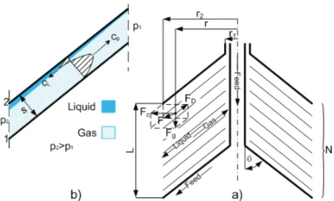
Figure 4. Forces acting on a particle due to centrifugal acce-leration. FD – Drag, Fg – gravity, Fc – centrifugal, F – total.
The easiest fraction (gas) gets caught at the place closest to the rotation axis and directed to the centri-fugal compressor.
Innovations introduced in the separator construc-tion were as following [14,15]:
- the periphery edge of the upper and lower half of rotor is constructed as an impeller of pump for liquid transport;
- the sealing of impellers is done by mechanical seals, which are, also, axial bearings for rotator;
- the specific construction of the insert allows the liquid drops to be caught after a short fall and directs the drops towards the bottom of the rotor, towards the discharge opening;
- by introducing the centrifugal compressor into the separator construction, suction of mixtures (liquid-gaseous) is facilitated and also the losses of pressure are compensated.
The advantages of solutions thus formed are as following:
- central charging and self-suction make separator independent of auxiliary equipment (feed pump);
- the vortex tubes (1) conducted the largest drop-let separation. They are, sliding down the first disk, immediately directed to the drain hole in the body of the rotor.
- one engine controls the power of several sections, which on the other hand has an disadvantage that the conditions in the section cannot be independ-ently changed;
- combining radial–axial bearings, the great rota-tion speeds can be achieved together with excellent rotor stability;
- by moving away from the rotation center, the liquid fraction is exposed to the greater centrifugal force (due to greater density), which results in better quality separation from the gas fraction.
Some of the weaknesses that should be mentioned are:
- the complex construction;
- heavy-duty, low temperature, leading to the frequent breakdowns;
- it is necessary to invest significant means into the technical solution in the prototype phase, so that all theoretical and constructive assumptions can be verified.
Perceived weaknesses in the theoretical consider-ations [16], while defining the separation quality and capacity, imposed the need for reconsidering the exist-ing theoretical basis for definexist-ing the separation capa-city and quality. The acquired results of the theoretical considerations are given in this paper.
THEORETICAL BASES
Many researchers [1–4,10,16,20,21] have dealt with this problem and the acquired results emphasize the following: the solid particle (droplet) size (ds in m),
settling velocity (cg in m/s), length of settling road (L in
m), settling time (t in s) and viscosity (η in Pas) of the feed fluid have a great influence to the separation feed flow rate and quality of separation.
The movement of the particles within the rotor and the separator’s rotor insert is complex and consists of (Figure 4):
- vortex movement for rough separation of large drops in the pipe (1);
- radial movement under the influence of the centrifugal force in the insert of the rotator (2);
- axial movement vertically upwards, in the inner space of rotator;
- tangential movement of the liquid fraction – on disc surface and in the canals of the collection rings (7).
Separation of the mixture (in pre-separator, I) is theoretically and experimentally very well treated [3,4,16,17] and, in this paper, of particular interest is the movement of mist (gas–liquid CO2) into the gaps of
the rotor insert.
Moving practically (tg θ = g/ω2r << 1) radial in the gap between the disks, the liquid particle touches the inner disc side, Figure 4, and while sliding on it comes to the disk’s exit edge (radius r2). The layer thickness, at
the contact point disk-mixture, is proportional ν and inversely proportional ωL . The minimal values of the boundary layer thickness are [22]:
,min 3.71 , m
l
L ν δ
ω
= (1)
for laminar flow, and:
1 5 ,min 0.525 2 , m
T
L R
ν δ
ω
=
(2)
The gas, being the lighter fraction, fulfills the space bordered by the exterior disc surface (1), Figure 4, and a layer of liquid CO2 which lies on the inner surface of
the disc. In this gap the gas moves from the periphery to the rotation center at the speed of cg. The amount of
fluid (mixture of gas–liquid) which flows through the insert gap depends on the total flow qv (m3/s) through
the gaps and the number of gaps (z = N–1) [17]:
3
, m /s v q q
z
= (3)
There are two objectives of this theoretical con-sideration:
1. Definition of pressure drop in the inset (2) of rotor, that is of particular importance for separation efficiency and the size of the gap between the disks;
2. Defining the stability of liquid film flow, that is of particular importance for the quality of the final product.
During this complex movement, of gas–liquid mix-ture, the following resistances appear in:
- Liquid fraction friction against the inner disc sur-face (2);
- Gas fraction friction against the layer of liquid fraction;
- Gas friction against the exterior disc surface (1). The consequence of friction are the losses (pressure drop) which are important for defining flow and power of the centrifugal separator. For all considerations [16,23] the common thing is that the friction coefficient (f), significantly depends on:
- Gap size (s≤R2)
- Relative gap size, s R/ 2;
- Relative roughness size, Δ/R2
- Reynold’s number:
2 2 Re
2 R q
s
ω
ω
π ν ν
= =
It is important to note that the angular velocity of liquid (ωL) and gas (ωG) are not the same to angular velocity of disc (ωD), because the process of drive transfer, in rotating disc, is accompanied by slides. Many studies [17,22] confirm the position:
L L D
G G D
K K
ω ω
ω ω
=
= (KL≈ 0.5; KG≈ 0.3) (4)
It is customary that the coefficient of friction at the contact: the fluid–disc wall, is defined by [20,21]:
n G
G G
Rc
f C
ν
−
=
;
n L L L
Rc
f C
ν
−
=
(5)
where:
CG = CL = 0.0791, nG = nL = 0.25 – for turbulent flow;
CG = CL = 16, nG = nL = 1 for laminar flow.
A similar, but in our opinion, for these conditions acceptable, approach has Vasiljcev [22] that the friction coefficient is defined by the expression:
2
( ) Remi ni
fo s
c A
R
χ ω
= (6)
The coefficient values: Aχ, mi, ni, depend on the
fluid flow regime and are given in Table 3. Table 3. The coefficient values: Aχ, mi, ni
Flow mi ni Aχ
Laminar –1 –1 1−
(
1−χ)
4Turbulent –0.25 –0.25 1−
(
1−χ)
4.75The coefficient χ=
(
R2−r)
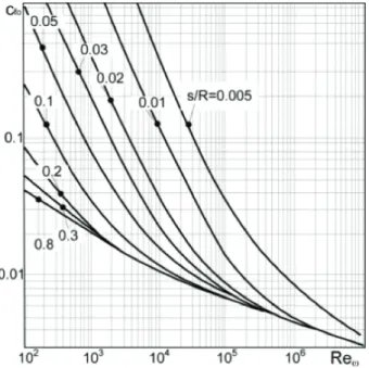
/R2 defines how soaked is the disc surface (for: r = r2, χ = 0, i.e., the disc issurrounded by gas; for r = 0, χ = 1, i.e., the disc is com-pletely covered with liquid). Calculation of (cfo) is
com-plex, and a digram given in Figure 5 [22], is most fre-quently used.
Figure 5. Friction coefficient cfo.
The pressure drop, in insert of rotator, is defined by the formula (1 – gas; 2 – liquid CO2):
1,2
2 2 2
1,2( 1,2 ) 2 1 (1 )
2 D
p f K ω R χ ρ
Δ = − − , Pa (7)
min. (3.2 4.2) , m
L
s ν
ω
= − (8)
The actual size of the gap is:
min. 2 l T( ), m
s=s + δ (9)
For r2 = 0.1 m, ωL = 150 s –1 and
ν= 1×10⁻⁶ m2/s the optimal gap value is: 0.0007 m (0.7 mm). Gaps are commonly 2–3 mm.
The analysis of fluid behavior at the contact of gas-liquid CO2 is important for two reasons:
- defining the drag force on the contact of liquids-gas boundary zone and its impact on the capacity and quality of separation;
- defining the impact of gas flow on the stability of liquid film and quality of separation.
The micro-mixture is formed on the contact layer with density of:
M PG G PL L
ρ = ρ + ρ , kg/m3 (10)
Speed of movement in the boundary zone is [23]: G G G L L L
M
P c P c
c ρ ρ
ρ +
= , m/s (11)
Mode of movement in this zone defines Reynold’s number:
Reω cs ν
= (12)
for:
- Re < 50 motion is laminar, with a flat area on the liquid-gaseous contact;
- 50 <Re < 400 motion is laminar, with a wavy surface of liquid–gaseous contact;
- Re > 400 motion is turbulent. Shear stress is:
2
1 2 LG fLG Gc
τ = ρ (13)
As the fluids (gas and liquid CO2) move in opposite
directions, the critical velocity, cc, is defined by the
expression [20]:
0.5
2( ) L
c
L G
g
c σ ρ
ρ ρ
= , m/s (14)
Group of authors [20] proposed that the coefficient of friction (fLG), in this zone, is defined by comparing
the coefficient of friction of pure fluids in contact with the wall.
For (cG + cL) < cc coefficient of friction is:
5 LG
G f
f = (15)
For (cG + cL) ≥ cc coefficient of friction is: 0.5
2
5 15( ) 1
LG G L
G c
f c c
f D c
δ +
= + −
(16)
Also in use is the expression [21]:
0.687
4 1.16
24 0.42
(1 0.15Re )
Re 1 4.25 10 Re
LG
f ω
ω ω
−
= + +
+ × (17)
At low content of liquid and speeds that are less than the speed of sound, the liquid film is separated, from the disc, in compact layer length 2–3 mm. After that, the film breaks up into the droplets of 0.1–0.2 mm in diameter.
The aim of this part of the article is to find criteria which will define the stability of liquid film flow. From the theory of the liquid film flow [23–25] and analysis of the gas influence on the stability of the liquid film (Kelvin–Helmholty instability) the Weber’s number required criteria:
2
Gc d
We ρ
σ
= (18)
When the value of Weber’s number is less than 5.5, the flow of the liquid film is stable and it is not breaking up into droplets. Time, until film reach the critical stage, is: 1.65 L kr c G t c ρ δ ρ
= , s (19)
Critical areas are zones of maximum diameter of the disc (r2), where the speed of the liquid fraction (cL = = r2ω) has maximum or zone of minimum diameter of the disc (r1), where the rate of gaseous fractions (cG)
has maximum. The influential value for gas and liquid carbon dioxide are shown in Table 4.
Table 4. Physical properties of liquid CO2 and gas CH4
Methane CH4, gas Carbon dioxide CO2, liquid Temperature, t = –70 °C Temperature, t = –70 °C
Pressure, 5 bar Pressure, 5 bar
Density, 4.9 kg/m3 Density 1216.7 kg/m3
Viscosity Viscosity Dynamic, 7.93×10⁻⁶ Pa s Dynamic, 0.32×10⁻³ Pa s
Kinematic, 1.618×10⁻⁶ m2/s Kinematic, 0.226×10⁻⁶ m2/s
Surface tension, σ=0.001 N/m
DISCUSSION
numerous gas deposits. The technological procedures, used for cleaning the natural gas, are numerous, but it has been proved that many of them are connected to the complex technology which requires expensive facilities and great operation expenses. The conden-sation of the polluting gases and their removal from the natural gas is one of the directions of further develop-ment in this field. The research is facing two directions:
- Finding a technologically, technically and econo-mically feasible solution for the condensation of carbon dioxide.
- Finding a technically and economically feasible solution for the separation of liquid carbon dioxide (CO2) from gas (CH4).
Based on the analysis of the so far developed procedures, the cleaning of natural gas by separation, a bigger group of authors [3,4,14] as well as authors of
this paper [16], observed numerous disadvantages of which we emphasize the following:
- separation in gas-gas separators is slow and economically unacceptable for the cleaning of natural gas;
- separation of the natural gas through conden-sation CO2 on the rotor wall is also inefficient and
unacceptable for working with natural gas;
- For now, the most suitable solution, the C3-sep procedure with RPS-separators for separating the liquid fraction is more and more accepted in the gas industry, but this solution also has certain disadvantages, some of which the authors have presented in this paper.
The authors have tried to remove the observed disadvantages suggesting a construction of a new sepa-rator [14,15], which in their opinion will not only remove the observed disadvantages, but will also enable a continual separation of the natural gas with a continual discharge of pure gas and products (impu-rities) of separation. While working on the develop-ment of a prototype of this separator, the authors face various theoretical and technical problems. Some of these problems the authors represented in their paper that analyze the separation of the liquid, liquid-solid mixture [16].
Why is it important to precisely define the friction coefficient in the rotor separator insert? First of all for the simple need of defining the pressure drop in the
rotor separator insert. The construction of the insert is such that in a certain operation regime (gap size, angular speed) it can act as a disc pump or centrifugal seal, i.e., complete termination or reverse gas move-ment can appear.
The thickness of the liquid layer, on the disc, and its speed can form a drag force which will draw a great amount of gas to the disc periphery. The consequence of such movement is the reduced capacity and lower quality of separation. This paper gives theoretical solutions of the observed problems.
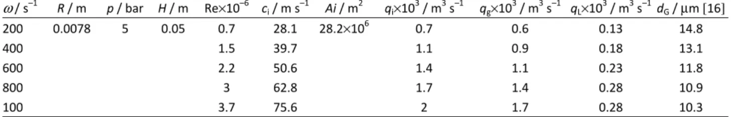
Relying on established theoretical assumptions we, in this paper, show the process of defining the diameter (dg) of liquid droplets, given in Table 5 and
Figure 6.
Also we calculated the values of the Weber’s num-ber, which is important for the stability of the flow of
liquid, given in Table 6. Both calculations were done for a prototype that was also used for the treatment of solid–liquid mixtures and its reconstruction is in prog-ress.
Figure 6. Dependence dg = f(ω).
The fact is that each theoretical solution must be tried out on a prototype and the aim of the next paper will be the procedure and the results of research, i.e. confirmation or negation of certain theoretical assump-tions.
CONCLUSION
By presenting the new technical solution of the centrifugal separator, the authors point to the expected Table 5. Definition of dg for CH4–liquid CO2
ω / s–1 R / m p / bar H / m Re×10–6 ci / m s–1 Ai / m2 qi×103 / m3 s–1 qg×103 / m3 s–1 qL×103 / m3 s–1 dG / µm [16]
200 0.0078 5 0.05 0.7 28.1 28.2×10⁶ 0.7 0.6 0.13 14.8
400 1.5 39.7 1.1 0.9 0.18 13.1
600 2.2 50.6 1.4 1.1 0.23 11.8
800 3 62.8 1.7 1.4 0.28 10.9
improvements, both in the capacity and the quality of gas-liquid mixture separation. Innovations introduced in the separator construction are:
- the periphery edge of the upper and lower half of rotor is constructed as an impeller for the pump for liquid transport;
- the sealing of impellers is done by mechanical seals, which are, also, axial bearings for the rotator;
- the specific construction of the insert allows the liquid film to be caught immediately after a very short fall, directing liquid to the bottom of the lower half of rotor and discharging them immediately next to the rotor’s wall against which they slide to the discharge opening;
- by introducing the centrifugal compressor into the separator construction, suction of mixtures (liquid– –gaseous) is facilitated and also the losses of pressure are compensated.
The aim of this paper was to point out the certain advantages of the new solution, by presenting the new solution, but what is more important to form theo-retical basis for the calculation and construction of the separator. This paper emphasizes the technological part: defining the pressure drop in the separator insert and criteria (critical velocity, cc) for stability of liquid film
flow. Of course, such theoretical considerations must be checked through laboratory and semi-industrial experiments, since the next paper will be dedicated to that task.
Nomenclature
A, χ, mi, ni - Coefficients c, ci cm - Speed, m/s f, fo, - Coefficient of friction
fLG - Coefficient of friction at the contact of gas–liquid K, KL, KG - Coefficients
N - The number of gaps q - Flow through the gap, m3/s qv - The flow through the separator, m
3
/s R, R2- Disk radius, m
Re, Reω- Reynolds number P - Percentage, %
Δp - Pressure drop, Pa
s - The thickness of the gap, mm We - Weber number
δ, δL, δT - The thickness of the layer of liquid, m
Δ - Absolute roughness, mm
ρ, ρi, ρm- Density kg/m3 ν - Kinematic viscosity, m2/s
ωL,ωDLG - The angular speed of the liquid, disc and gas, s–1
σ - Surface tension, N/m
τ - The shear stress, Pa
Acknowledgments
This paper is the result of the project (Project No 33001) financed by the Ministry of Education, Science and Technological Development of the Republic of Serbia. We give many thanks to the Ministry for the support that they have provided during this project. REFERENCES
[1] M.N. Bazlov, A.I. Zukov, Processing, separation and transportation of natural gas, Nedra, Moscow, 1998. [2] E. Mondt, Centrifugal separator of dispersed phases,
PhD Thesis, Eindhoven University, 2005.
[3] R.J.E. Wissen, Centrifugal separation for cleaning well gas streams: from concept to prototype, PhD Thesis, Eindhoven University, 2006.
[4] E.A.J. Watering, Prototype centrifugal natural gas cleaner. 2007. Report number WPC, Eindhoven Univer-sity, 2007.
[5] R. Wissen, G.M. Brouwers, Gas Centrifugation with wall condensation, AIChE J. 52 (2006) 1271–1274.
[6] M. Živkovic, Investigation of efficient combustion of natural gas with high carbon dioxide content, PhD Thesis, Faculty of Mining and Geology, Belgrade, 2010. [7] M. Zivkovic, M. Adzic, V. Fotev, A. Milivojevic, V. Adzic,
D. Ivezic, B.Cosic, Influence of carbon dioxide content in biogas on nitrogen oxides emissions, Hem. Ind. 64
(2010) 439–445.
[8] D. Danilović, V. Karović Maričić, R. Šećerov Sokolović, D. Ivezić, M. Živković, Laboratorijsko ispitivanje i simulacija procesa taloženja parafina u naftnoj bušotini polja Turija u Vojvodini, Hem. Ind. 65 (2011) 249–256.
[9] M. Adžić, M. Živković, V. Fotev, A. Milivojević, V. Adžić, Uticajni parametri emisije azotnih oksida vihornog gori-onika mikroturbine sa pilot gorionikom, Hem. Ind. 64
(2010) 357–363.
[10] E.S. Rosa, F.A. Franc, G.S. Ribeiro, The cyclone gas–liquid separator: operation and mechanistic modeling, J. Pet-rol. Sci. Eng. 32 (2005) 87–101.
Table 6. Definition of Webers number
ω / s–1 qT×106 / m s–1 cT×103 / m s–1 cg / m s–1 ρm / kg m–3 c / m s–1 f τT×10–6 / Pa δT / µm We
200 0.13 0.4 2.17 5.01 2.12 0.0083 0.8 100 0.157
400 0.18 0.6 3.26 3.19 0.0072 1.5 70 0.209
600 0.23 0.8 3.98 3.89 0.0066 5.5 58 0.230
800 0.28 1 5.07 4.89 0.0062 3.7 50 0.270
[11] GEA, New dimensions in treatment systems–separators, GEA-Westfalia separator, 2007 (www/westfalia.com). [12] Haldex, Hydraulic Systems Division, 2011
(www.h-bus.haldex.com).
[13] Vartisila. Oil mist separation-clean crankcase ventilation, 2010 (www.vartisila.com).
[14] V. Batalovic, Centrifugal separator with continual lateral discharge, Intellectual property journal, Pat. no 48851-P-216/94. Belgrade, Serbia, 2001.
[15] V. Batalovic, Centrifugal separator with pump for con-tinual lateral discharge, Intellectual property journal, Pat. no 48852-P-556/96. Belgrade, Serbia, 2001.
[16] V. Batalović, Centrifugal separator, the new technical solution, application in mineral processing, Int. J. Miner. Process. 100 (2011) 86–95.
[17] M.E. Afonin, P.N. Belanin, New centrifugal separators for oil cleaning, Vestnik Masinostroenia 12 (1978) 38– –42.
[18] H. Axelsson, B. Madsen, Centrifuges, sedimentations, Alfa Laval separation AB, Tumba, Sweden, 2003. [19] Mueller, Fundamentals of gas solids/liquids separation,
Mueller Environmental Designs, Inc. Huston, 2007 (www. muellerenvironmental.com).
[20] E.J. Halter, Separation handbook, First ed., Burgess Manning Company, Orchard Park, NY, 1966.
[21] G.P. Williems, Condensed rotational cleaning of natural gas, PhD Thesis, Eindhoven University Press, 2009 (www.liekewillems.nl).
[22] E.A. Vasiljcev, V.V. Nevelic, Pumps sealing, Masinostro-enie, Moscow, 1986.
[23] Y. Liu, H. Zhang, S. Wang, J. Wabg, Gas–liquid interfacial friction factor for the transition stratified to slug flow, Microgravity Sci. Tec. 20 (2008) 299–305.
[24] V. Stevanovic, S. Prica, B. Maslovarić, Multi-fluid predict-tions of gas–liquid two-phase flows in vertical tubes, FMA Transactions 35 (2007) 173–181.
[25] I.I. Krilov, Theory of turbomashines, Nedra, Moscow, 1986.
[26] A.H.M. Birgadeau, Modeling and numerical investigation of high pressure gas-liquid separation, PhD Thesis, Norvegian University of Science and Technology, 2007. [27] J. Carol, Phisical properties relevant to acid gas
IZVOD
CENTRIFUGALNA SEPARACIJA TEČNOG UGLJEN-DIOKSIDA IZ PRIRODNOG GASA Veselin B. Batalović, Dušan Š Danilović, Marija A. Živković
Univerzitet u Beogradu, Rudarsko–geološki fakultet, Beograd
(Naučni rad)
Prirodni gas se sve više koristi u globalnoj energetskoj potrošnji pre svega zbog lakog transporta do potrošača kao i zbog relativno malog uticaja na životnu sredinu. Nove tehnologije, kao što je konverzija u tečnost, olakšavaju transport i primenu prirodnog gasa. Prirodni gas, dobijen sa eksploatacionog polja, prate brojni zagađivači (tečni, čvrsti i gasoviti) koje treba ukloniti kako bi tržišna vred-nost gasa bila veća. Čvrsti i tečni zagađivači se relativno lako uklanjaju, ali više od 16% trenutno poznatih rezervi gasa ne može se koristiti zbog teškog uklanjanja gasovitih zagađivača (CO2 i/ili H2S: CO2 > 10%, H2S > 5%). Tradicionalna tehno-logija, kao što je amino-tretman, se ne može ekonomično primeniti za uklanjanje ovako velikih količina zagađivača. U radu se istražuju mogućnosti primene centri-fugalnih separatora za rešavanje ovog problema. Posle analize postojećeg stanja, u centrifugalnoj separaciji prirodnog gasa, neke inovacije u konstrukciji separatora su predložene. Inovacije se sastoje pre svega u mogućnostima, separatora da u jednoj celini, pogonjenoj jednim motorom, realizuje proces čišćenja gasa od: č vrs-tih, tečnih, a posle tretmana hlađenjem, i gasovitih zagađivača (CO2 i/ili H2S). Prednosti ovako koncipiranog tehničkog rešenja bi bile: centralno punjenje i samopražnjenje separatora; jedan motor pogoni čitavo postrojenje; kombinovano radijalno–aksijalno oslanjanje obezbeđuje stabilan rad separatora i pri velikim brzinama rotacije; moguće je postići velika centrifugalna ubrzanja što olakšava proces razdvajanja. Naglasak, u ovom radu, je dat na teorijska razmatranja pro-cesa razdvajanja tečnog ugljen-dioksida (CO2) od gasovitog metana (CH4). Cilj predloženih teorijskih razmatranja je da se složena teorijska osnova prilagodi potrebama inženjera pri razvoju, konstruisanju i izradi ovih postrojenja. Kapacitet i kvalitet, separacije su parametri koji čine osnovu ekonomičnosti procesa šišćenja prirodnog gasa. Ovi parametri, uz stabilnost rotora separatora, su osnovni kri-terijumi za ocenu kvaliteta konstrukcije jednog separatora. Naravno da se ovako formirane teorijske osnove moraju detaljno proveriti ispitivanjima na laborato-rijskim, poluindustrijskim i industrijskim postrojenjima. Deo ovih ispitivanja je urađen [13,16] ali suštinska ispitivanja tek slede.
Ključne reči: Gas • Kalorična vrednost •
![Table 1. Acid natural gas volumetric composition [6]](https://thumb-eu.123doks.com/thumbv2/123dok_br/18406439.359270/1.892.81.814.863.1003/table-acid-natural-gas-volumetric-composition.webp)