Micro-Scale Abrasive Wear Testing of CrN Duplex PVD Coating on Pre-Nitrided Tool Steel
Rafael David Mercado-Solisa*, José Guadalupe Mata-Maldonadoa, Miguel Angel Quinones-Salinasa,
Eduardo Rodriguez-de-Andab, Rumualdo Servín-Castañedac
Received: October 07, 2016; Revised: May 03, 2017; Accepted: May 22, 2017
Speciic wear rates were calculated from a series of micro-scale abrasive tests by means of the calotte-grinding method. The tested material was a CrN coating deposited by arc evaporation on ion-nitrided AISI H13 steel. Characterizations included: phase analysis, chemical composition, metallography, microhardness, micro-scratch resistance and nano-indentation hardness. On wear testing, the counter body was a 30 mm diameter steel ball rotating at a tangential speed of 9.42 m/min and normal load of 0.54 N. The abrasive was a mono-crystalline diamond micro abrasive paste, 1 micrometer grit. Wear volumes were calculated by measuring the wear scars at various test intervals. In non-perforating tests, Archard’s wear equation was directly employed for calculating coating wear rate as the slope of the linear least square data it. In perforating tests, Allsopp’s method was employed for the simultaneous determination of coating and substrate wear rates, from the slope and intercept values of the linear least square data it. Coating speciic wear rate values obtained from both non-perforating and perforating tests were very consistent, with a relative diference within 6%. Relative errors in speciic wear rate values were estimated to be of the order of 0.05 for the coating and 0.2 for the substrate.
Keywords: Micro-scale abrasion, duplex surface treatment, speciic wear rate, calotte grinding method, PVD coating, ion nitriding
* e-mail: [email protected]
1. Introduction
In surface engineering, the term duplex treatment refers
to the sequential application of two surface modiication technologies with the aim of producing a composite surface of such combined properties that are not obtainable through any of the individual technologies1. One type of duplex treatment
of great technological importance is the process combination of atomic difusion hardening followed by the deposition of a thin hard coating (oftentimes a nitride-type compound). More speciically, PVD coating of nitrided steel substrates is perhaps the most popular duplex treatment technology currently in use2-6. Duplex surface treatments have found extensive use in tribological applications because of their low friction and adequate balance between surface hardness, shear stress resistance, fracture toughness and load bearing capacity7-9. In addition, due to their chemical inertness, PVD coatings are very well suited for resisting corrosion10-14. Some typical application examples of duplex surface treatments may be found in forming dies, casting molds, cutting tools and prosthetic implants15-20. Abrasive wear resistance is a key aspect in duplex-treated surfaces. However, since PVD coating thickness is only about a few micrometers and the abrasive particles may be even smaller, the term micro-scale
abrasive wear better describe the abrasion of thin coatings, thus distinguishing it from bulk (‘macro-scale’) abrasive wear21-23. Despite the advantages of duplex treatments in terms of wear and corrosion resistance, fracture toughness is usually compromised. Brittleness may lead to premature failure due to cracking, spalling or delamination. Therefore, a thorough optimization of the duplex treatment parameters along with extensive characterizations should always be performed in order to achieve the optimal combination of properties in service. These characterizations shall include microstructural analyses24-26, hardness, adhesion, toughness, wear resistance, etc.27-32. Chromium nitride (CrN) PVD coatings are extensively used in a wide range of engineering applications involving friction and wear. However, most of the studies reported in the literature have been performed assessing the macro-scale wear characteristics of this coating. The aim of this work was to assess the micro-scale wear behavior of a CrN PVD coating deposited on ion-nitrided AISI H13 tool steel (duplex treatment).
The calotte-grinding method, which is widely employed for coating thickness measurements33, also constitutes the basis
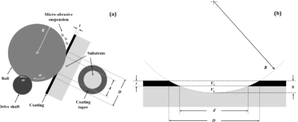
for micro-scale abrasive wear testing. This method relies on the production of well deined calotte-shaped wear scars and their subsequent measurement for volume loss calculations. The testing principle is shown schematically in igure 1a, where a hard steel ball spins against a coated surface under
a Universidad Autónoma de Nuevo León, San Nicolás de los Garza, Nuevo León, 66455, México
b Universidad de Guadalajara, Guadalajara, Jalisco, 44430, México
a steady rotational speed transmitted via a driving shaft. A micro-abrasive particle suspension is dosed on the ball and drawn inside the contact, resulting in the progressive removal of the coating. The wear scars exhibit a large degree of conformity to the geometry of the ball (i.e. fully imposed shape). In other words, it is assumed that the shape of the ball is perfectly “copied” by the surface as the former may very efectively occupy the volume that is removed from the latter during wear. Under these conditions, the total wear volume
VT may be estimated from the radius of the rotating ball R
and either the produced calotte diameter D or its depth h as:
substrate calotte wear volume VS may be estimated from
equation 1 as a function of the inner diameter d as:
( )
V
R
D
1
64
T 4r
=
( )
V
Th R
2
2
r
=
Where h may be approximated as:
( )
h
R
R
D
4
3
2 2
=
-
-In the practice, however, diameter measurements are preferred over depth measurements for volume calculations because they are more easily performed using a standard optical microscope.
There are two types of micro-scale abrasion tests: non-perforating and non-perforating; the main diference being the extent of ball penetration with respect to coating thickness. In a non-perforating test, the ball does not penetrate into the substrate, thus, only coating removal occurs and the wear scar is accommodated entirely within the coating. Therefore, the direct usage of equations 1 and 2 is adequate for the determination of the wear volumes in non-perforating tests. However, in very thin and/or very fast wearing coatings, the ball may perforate the coating after only a few rotations. Thus, a composite contact occurs as the total wear volume is accommodated partly in the coating and partly in the substrate, as shown in igure 1b. In perforating tests, the
Figure 1. (a) Schematic representation of micro-scale abrasion tests. (b) Cross-section view and deinition of volumes related to parameters d, D, R, h and t.
( )
V
R
d
4
64
S
4
r
=
Thus, the coating wear volume VC may be calculated by
combining equations 1 and 4 as follows:
(
) ( )
V
V
V
R
D
d
64
5
C T S
4 4
r
=
-
=
-In most cases, the inner diameter is better deined and more accurately measured than the outer diameter. Therefore, the use of the inner diameter and the coating thickness t instead
of the outer diameter is usually preferred for calculating VC:
(
)
( )
V
t
d
Rt
4
4
6
C
2
r
=
-Where t may be derived from the following expression33:
( )
t
R
d
R
D
2
2
7
/ /
2 2 1 2 2 2 1 2
=
#
-
S
X
&
-
#
-
S
X
&
In non-perforating tests, the well-known Archard’s wear equation may be directly applied to relate the volume of coating material removed Vc to the product of the normal
force N and sliding distance S:
( )
V
C=
k SN
C8
Where kC is the coating speciic wear rate.
Rutherford and Hutchings22 proposed the fundamental
wear equation for a single set of data obtained from perforating tests, taking into account the composite contact:
( )
SN
k
V
k
V
9
S S C C=
+
Where kS is the substrate speciic wear rate.
determination of kC and kS by linear least square it from a
single set of perforated tests data; the slope being 1/kS and
the intercept 1/kC . Thus, dividing equation 9 by VC we obtain:
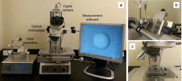
will resume on the same calotte for longer sliding distances, the vice may be installed on the adjustment pins, allowing exact repositioning of the ball for continued testing. A tactile control panel allows the user to input, save and modify the desired testing parameters which include: grinding speeds between 1.4 and 55.8 m/min, shaft rotational speed from 30 to 500 rpm, number of shaft revolutions from 20 to 15,000, grinding distance from 1.2 to 870 m and ball diameters from 12 to 40 mm. The micro-abrasive suspension may be delivered either manually using a pipette or automatically by means of a dosage system consisting of a syringe attached to an air pump. Typically, only one drop (approximately 35 mg) of micro-abrasive suspension is required at the beginning of each test. Alternatively, a small quantity of metallographic grade crystalline micro-abrasive diamond paste may be smeared on the ball before starting a test.
3. Materials
Round plates (∅ 30x10 mm) made from AISI H13 hot-work tool steel were employed as the substrate material in this study. The chemical composition of the steel, obtained through X-ray luorescence, is presented in table 1. Prior to surface modiications, the substrates were vacuum heat treated by austenitizing, quenched and double tempered to hardness 46 HRC, followed by surface reconditioning by grinding and cleaning. The surface modiications consisted in the production of a CrN coating structure via a duplex treatment (ion nitriding + PVD) in discontinuous cycles. Comprehensive details of the duplex treatment process parameters employed in this study are presented in table 2. Process 1 corresponds to the ion nitriding stage, process 2 was an intermediate step where the substrates were polished and cleaned to produce a fresh metallic surface to enhance coating adhesion and process 3 was the PVD coating deposition stage itself. The test balls (∅ 30 mm, 110 grams)
(
)
V
SN
k V
V
k
1
1
10
C S C
S
C
=
+
Any measurement errors in d, D, h and t will evidently
propagate into the values of kC and kS. Kusano et.al.35
presented a comprehensive analysis of the inluence of measurement errors on the reliability of the calculated wear rates. Evidently, as the relative measurement errors in d and t decrease, the relative errors in both kC and kS decrease.
In addition, it was shown that as the ratio kC /kS and/or the
dimensionless parameter d2/Rt decrease, then the relative
error in kC decreases but that in kS increases. The parameter d2/Rt is proportional to the ratio (h-t)/t, i.e. the extent of
substrate penetration depth with respect to coating thickness.
2. Testing Apparatus
A commercial micro-scale abrasive wear testing device, denominated ‘kaloMAX NT II’, was employed in this study (Figure 2). This apparatus allows testing under the free-rotating ball coniguration, in which the ball leans freely against the test sample at a 60º angle while being supported by two rubber rings at both sides of a V-shaped groove in the shaft. In this way, the ball’s own weight produces the contact pressure against the sample. As the shaft rotates, slippage between the ball and the rubber rings is minimized due to the high friction of the contact, while relative motion between the ball and the sample is efectively introduced. In the device, the sample is clamped to a vice that is attached to an X-Y compound stage by adjustment pins. When the wear scar is measured, the entire vice may be removed with the sample in place and put under the microscope. If a test
Table 1. Chemical composition analyses of the AISI H13 tool steel substrates (wt.%, balance Fe).
Cr Mo V C Si Mn
5.3 1.3 0.9 0.39 1.0 0.4
Table 2. Duplex treatment process parameters for surface modiications.
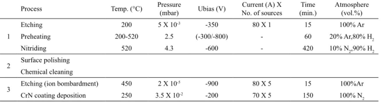
Process Temp. (°C) Pressure (mbar) Ubias (V) No. of sourcesCurrent (A) X (min.)Time Atmosphere (vol.%)
1
Etching 200 5 X 10⁻³ -350 80 X 1 15 100% Ar
Preheating 200-520 2.5 (-300/-800) - 60 20% Ar,80% H2
Nitriding 520 4.3 -600 - 420 10% N2,90% H2
2 Surface polishing
Chemical cleaning
3 Etching (ion bombardment) 450 2 X 10
-5 -900 80 X 5 15 100%Ar
CrN coating deposition 250 3.5 X 10⁻² -200 70 X 5 150 100% N
2
were made from hardened steel 100Cr6 for rolling bearings (AISI 52100 equivalent), in compliance to ISO 3290-136 for
inish requirements.
4. Experimental procedure
4.1. Materials characterizations
Samples from the ion-nitrided substrates after process 2 were subsequently characterized by optical metallography, GDOES elemental depth proiling, Vickers microhardness depth proiles and X-ray difraction (XRD). Duplex-treated samples obtained after process 3 were characterized by EDS chemical composition analysis, XRD, micro-scratch resistance and nano-indentation. All XRD analyses were performed for the purpose of phase constitution identiication using a Philips PW1710 X-ray difractometer with Cobalt-K alpha radiation. Measurements were conducted using a scanning step of 0.02º for difraction angles (2θ) from 30º to 120º for the ion-nitrided substrate and from 30º to 105º for the CrN PVD coating. Micro-scratch resistance was measured using a CSEM Instruments Revetest scratch tester. The total scratch length was 15 mm and the indentation forced was progressively applied from 0.137 N to 150 N at constant loading rate 100 N/min and travel speed 9.692 mm/min. The indenter was a diamond Rockwell C conical tip of radius 200 μm and 120º angle apex. During the test, sensors signals for normal load, tangential load and acoustic emission were acquired as a function of scratch distance. Friction coeicient was calculated as the ratio of tangential to normal forces. Coating scratch resistance is expressed in terms of the magnitude of the indentation force at which various forms of coating failure are induced (critical loads), from cohesive to adhesive failure types: Lc1 cracking, Lc2 desquamation, Lc3 spallation and Lc4 delamination. Critical loads were
determined from strong signal variations in combination with scratch observations using a microscope. Hardness and elastic modulus of the PVD coating were measured using
a CSEM Instruments NHT nanohardness tester itted with a Berkovich diamond tip. Coating thickness was measured beforehand via the calotte-grinding method, resulting in average thickness of 5.0 μm. In order to avoid the inluence of the substrate during the indentation measurement, the tests were set to a maximum penetration depth of 500 nm (10% of coating thickness) at loading and unloading rates of 2 μm/min, respectively. Arrays of twenty indentation measurements were performed, and the average indentation hardness and elastic modulus values were obtained.
4.2. Tribological tests
digital camera and imaging software (Figure 2). Median values of d and D were subsequently employed for wear
volume calculations.
5. Results and Discussion
5.1. Substrate characterization
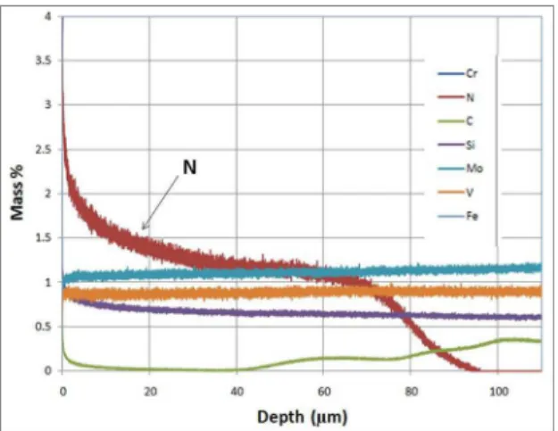
Figure 3 shows typical micrographs of the cross-section of the pre-nitrided substrate. As result of the ion-nitriding process, a difusion layer about 70 μm deep was developed (Figure 3a) and no compound -white- layers were formed. The contrast between the nitride layer and the base steel was achieved by chemical etching using a 4% Nital reagent. A transition zone between the difusion layer and the base steel is clearly seen in the microstructure as nitrogen concentration decreases with depth. This was further conirmed by the elemental depth proiling analysis performed using GDOES. In this sense, igure 4 demonstrates that the nitrogen mass concentration at the surface was approximately 4% and decreased rapidly to 1.5% at a depth of about 10 μm. Between 10 and 70 μm, nitrogen concentration decreased steadily to a value of 1% and then decreased rapidly to very low concentration levels beyond 90 μm in depth. The higher magniication micrograph of igure 3b (corresponding to the dashed box of igure 3a) conirmed that no iron nitrides were developed within the difusion layer as a result of the nitriding process. When present, iron nitrides are readily identiied as stringer-like phases that extend in the form of a continuous network along the grains within the nitrided layer. On the one hand, the presence of compound (white) layers has a negative efect on PVD coating adhesion and, on the other hand, iron nitride formation promotes brittleness and lowers the mechanical strength of the nitrided microstructure. Thus, the avoidance of these undesirable microstructural phases was achieved by extensive research on the optimization of the nitriding parameters, prior to this work.
Figure 3. (a) Optical micrograph the cross-section of the pre-nitrided steel substrate. (b) Microstructure of the highlighted region in (a). Figure 4. Results obtained from the GDOES elemental depth proile concentration analysis of the pre-nitrided steel substrate.
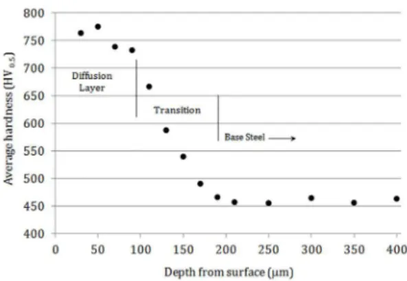
The microhardness depth proile of the pre-nitrided substrate is presented in igure 5. As expected, maximum hardness (~750 HV0.5) was measured near the surface. As nitrogen concentration decreased with depth, so did the average hardness of the difusion layer. At depths between 100 and 150 μm, hardness decreased progressively in the transition zone between the difusion layer and the base steel. From 200 μm onwards, the hardness remained unchanged at average values of approximately 460 HV0.5, which corresponds to the hardness of the quenched and tempered tool steel substrate (48 HRC).
Figure 5. Microhardness depth proile of pre-nitrided steel substrate.
Figure 6. X-ray difraction patterns of the ion-nitrided tool steel substrate.
5.2. Coating characterization
Figure 7 shows the results of the chemical composition analyses performed energy dispersive X-ray spectroscopy (EDS) on a metallographic micro-polished cross-section of the duplex-treated sample. The results of a line scan across the coating and the pre-nitrided substrate are shown on the left, while the quantitative results of chemical composition by EDS within the red boxes are presented on the right of the igure. High concentrations of chromium and nitrogen are present in the coating, with atomic percent 17.47% for nitrogen and 82.53% for chromium. Iron, chromium and nitrogen were conirmed as the main elements present in the substrate.
X-ray difraction patterns of the PVD coating revealed the characteristic peaks of chromium nitride phases CrN and Cr2N, as shown in igure 8. The α-Fe(N) phase from
the nitrided layer was detected in the spectra (as expected due to the inluence of the substrate), but their relative intensities were much smaller than those in the uncoated substrate (Figure 6).
The results from the scratch tests of the duplex-treated sample are presented in igure 9. Critical loads were established as 28N (Lc1), 62N (Lc2), 78N (Lc3) and 107N
(Lc4), corresponding to scratch lengths 3.0mm , 6.5mm ,
7.7mm and 10.8mm, respectively. At Lc1, the irst acoustic
emission signals were detected, corresponding to the onset
Figure 7. Cross-sectional EDS elemental analysis of the duplex-treated sample.
Figure 8. X-ray difraction patterns of the CrN PVD coating.
Figure 9. Scratch test results of the duplex-treated sample.
of coating failure by micro cracking. At Lc2, strong acoustic
emission signals were generated due to coating desquamation and subsequent spallation at Lc3. Finally, a sharp transition in
normal load is now fully supported by the substrate, a steady increase in friction coeicient is again observed due to the contact between the tip and the substrate. Nano-indentation tests of the PVD coating resulted in average indentation hardness of 18.32±2.8 GPa and elastic modulus 287±16 GPa. These results are consistent with values reported in the literature37-39.
5.3. Tribological tests
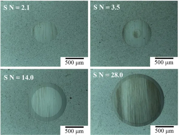
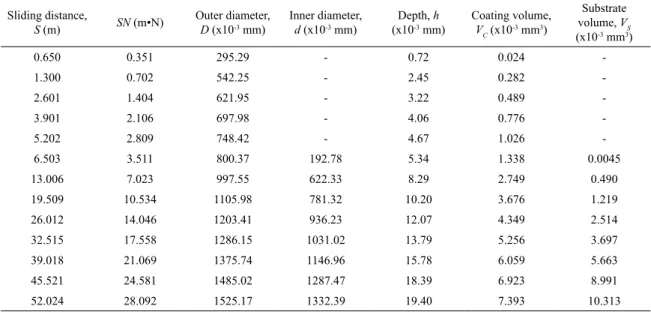
Micrographs of typical wear scars are presented in igure 10. In general, both the inner and outer diameters exhibited well deined edges, particularly at longer sliding distances. It is evident that the dominant wear mechanism was micro-abrasion as an array of ine micro grooves oriented in the direction of ball rotation was clearly observed inside the wear scars. The spacing between the grooves was approximately equal to the average size of the grit of the abrasive particles (1 μm) that are continuously being drawn within the contact by the rotating ball. No evidence of lack of adhesion was observed in coating/substrate interface and the coating taper exhibited a large degree of continuity (i.e. coating failure by cracking, pitting, etc. was not present). The experimental results of the micro-scale abrasion tests are summarized in table 3. In non-perforating tests, VC was calculated using equation
1, while in perforating tests, VS and VC were calculated via
equations 4 and 5, respectively. The total penetration depth
h was calculated from equation 3 which employs both the
ball radius R and the outer calotte diameter D. These results
are presented graphically in igure 11 as plots of SN versus:
diameters size (ig. 11a), wear volumes (ig. 11b) and total penetration depth (ig. 11c). Very small increments in sliding distances allowed performing ive measurements of the coating diameter D prior to its perforation. The onset of
composite contact took place between the ifth and the sixth measurement, once the ball penetration depth had exceeded the coating thickness of 5 μm. The approximate transition point between the non-perforating and the perforating contact regimes is indicated in igures 11 a-c by the vertical line at
SN ≈ 3.511 mN. It can be clearly observed from igure 11b that, once coating perforation has taken place, the rate of increase in substrate wear volume becomes larger than that of the coating because it is much softer; thus resulting in a faster wearing material, as discussed by Ramahlo40. At 21.069 < SN < 24.581 both the coating and the substrate
wear volumes are of equal magnitude; therefore, each one accounts for exactly one-half of the total wear volume,
VT. From this point onwards, the substrate wear volume
becomes more signiicant than the coating wear volume. In the non-perforating test interval, coating volume wear Vc
Table 3. Summary of micro-abrasive wear measurements: ball radius 15 mm, N = 0.54 N.
Sliding distance,
S (m) SN (m•N)
Outer diameter, D (x10-3 mm)
Inner diameter, d (x10-3 mm)
Depth, h
(x10-3 mm) Coating volume, V
C(x10
-3 mm3)
Substrate volume, VS
(x10-3 mm3)
0.650 0.351 295.29 - 0.72 0.024
-1.300 0.702 542.25 - 2.45 0.282
-2.601 1.404 621.95 - 3.22 0.489
-3.901 2.106 697.98 - 4.06 0.776
-5.202 2.809 748.42 - 4.67 1.026
-6.503 3.511 800.37 192.78 5.34 1.338 0.0045
13.006 7.023 997.55 622.33 8.29 2.749 0.490
19.509 10.534 1105.98 781.32 10.20 3.676 1.219
26.012 14.046 1203.41 936.23 12.07 4.349 2.514
32.515 17.558 1286.15 1031.02 13.79 5.256 3.697
39.018 21.069 1375.74 1146.96 15.78 6.059 5.663
45.521 24.581 1485.02 1287.47 18.39 6.923 8.991
52.024 28.092 1525.17 1332.39 19.40 7.393 10.313
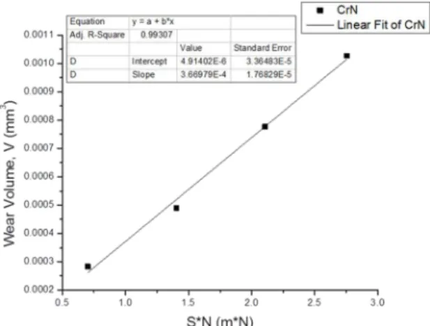
may be directly related to the product of the normal force
N and sliding distance S, the constant of proportionality
being the coating speciic wear rate kC (equation 8). The
results of SN versus VC for the non-perforating interval are
presented in igure 12. The least-squares regression line of best it of the data points is also included in the graph. The linear regression analysis resulted in a coeicient of determination R2 = 0.99307 and slope 3.66979E-4 mm3/mN,
which is the coating speciic wear rate, kC. Similarly, for
the perforated interval (composite contact), it is possible to simultaneously determine kC and kS by linear least square
it of a single set of perforated tests data; the slope being 1/
kS and the intercept 1/kC (equation 10). The results of VS/ VC versus SN/VC and the line of best it of the data points in
the perforating test interval are presented in igure 13. The least-square regression analysis yielded an R2 = 0.91357,
intercept 1/kC= 2566.53 mN/mm3 and slope 1/k
S = 853.28
mN/mm3; thus, k
C = 3.8963E
-4 mm3/mN and k
S = 1.1719E
-3 mm3/mN. Therefore, the calculated coating speciic wear
rates in both the non-perforating and the perforating test intervals were very consistent, with a relative diference below 6%. From these results, it is concluded that the nitride
Figure 12.SN versus VC for kC determination in the non-perforating test interval.
Figure 13.VS/VC versus SN/VC for simultaneous determination of kC and kS in the perforating test interval.
steel substrate wears at a speciic rate which is three times faster than that of the CrN PVD coating. Finally, based on the reliability method proposed by Kusano et. al.35, for the typical magnitudes of measurement errors of 1% in inner calotte diameter and 5% in coating thickness, d2/Rt=16 and
kC/kS=0.3324, the estimated errors in speciic wear rate of
this study were 0.05 for the coating and 0.2 for the substrate.
6. Conclusions
Speciic micro-scale abrasive wear rates of a CrN duplex coating deposited on pre-nitrided AISI H13 tool steel were calculated via the calotte grinding method in conjunction with Archard’s and Allsopp’s methods for wear data analysis. A remarkable consistency was found in both non-perforating and perforating tests, with a relative diference within 6%. In the former, coating speciic wear rate was 3.66979E-4 mm3/
mN, whereas in the later it was 3.8963E-4 mm3/mN. Speciic
wear rate of the pre-nitrided steel substrate was estimated in the order of 1.1719E-3 mm3/mN, i.e. three times greater
than that of the coating. Coating adhesion to the substrate did not seem to have an efect on the wear behavior, whereas hardness is directly related to the wear characteristics of the duplex system. The results from this work shall be taken as valid for the particular tribo-system under study and may serve for reference purposes. Other results may be expected in other testing scenarios involving diferent materials, velocities, loads, type of abrasive, temperature, humidity, etc.
7. Acknowledgements
The authors wish to thank the following institutions for the support provided for conducting this work: Universidad Autonoma de Nuevo Leon, Universidad de Guadalajara and Consejo Nacional de Ciencia y Tecnología (CONACYT-Mexico). We also wish to acknowledge the collaboration of the scientiic and technical staf from the Institute for Sustainable Technologies (ITeE-PIB) in Radom, Poland.
8. References
1. Bell T, Dong H, Sun Y. Realising the potential of duplex surface engineering. Tribology International. 1998;31(1-3):127-137. DOI: 10.1016/S0301-679X(98)00015-2
2. Mahboubi F, Fattah M. Duplex treatment of plasma nitriding and plasma oxidation of plain carbon steel. Vacuum. 2005;39(1-2):1-6. DOI: 10.1016/j.vacuum.2005.01.002
3. El-Hossary FM, Negm NZ, El-Rahman AMA, Hammad M. Duplex treatment of 304 AISI stainless steel using rf plasma nitriding and carbonitriding. Materials Science and Engineering:
C. 2009;29(4):1167-1173. DOI: 10.1016/j.msec.2008.09.049
5. Rousseau AF, Partridge JG, Mayes ELH, Toton JT, Kracica M, McCulloch DG, et al. Microstructural and tribological characterisation of a nitriding/TiAlN PVD coating duplex treatment applied to M2 high speed steel tools. Surface and
Coatings Technology. 2015;272:403-408. DOI: 10.1016/j. surfcoat.2015.03.034
6. De Las Heras E, Egidi DA, Corengia P, Gonzalez-Santamaria D, Garcia-Luis A, Brizuela M, et al. Duplex surface treatment of an AISI 316L stainless steel; microstructure and tribological behavior. Surface and Coatings Technology. 2008;202(13):2945-2954. DOI: 10.1016/j.surfcoat.2007.10.037
7. Pogrebnjak AD, Shumakova NI. Efect of ‘duplex’ treatment on changes of physical and mechanical properties of steel (0.3 wt% C). Surface and Coatings Technology. 1999;122(2-3):183-187. DOI: 10.1016/S0257-8972(99)00064-X
8. Walkowicz J, Smolik J, Tacikowski J. Optimization of nitirided case structure in composite layers created by duplex treatment on the basis of PVD coating adhesion measurement. Surface and
Coatings Technology. 1999;116-119:370-379. DOI: 10.1016/ S0257-8972(99)00079-1
9. Mesa DH, Pinedo CE, Tschiptschin AP. Improvement of the cavitation erosion resistance of UNS S31803 stainless steel by duplex treatment. Surface and Coatings Technology. 2010;205(5):1552-1556. DOI: 10.1016/j.surfcoat.2010.10.014
10. Chen C, Li Q, Leng Y, Chen JY, Zhang PC, Bai B, et al. Improved hardness and corrosion resistance of iron by Ti/TiN multilayer coating and plasma nitriding duplex treatment. Surface and
Coatings Technology. 2010;204(18-19):3082-3086, http:// dx.doi.org/10.1016/j.surfcoat.2010.03.017
11. Chala A, Nouveau C, Djouadi MA, Steyer P, Millet JP, Saied C, et al. Efect of duplex treatments by plasma nitriding and triode sputtering on corrosion behaviour of 32CDV13 low alloy steel. Surface and Coatings Technology. 2006;200(22-23):6568-6571. DOI: 10.1016/j.surfcoat.2005.11.036
12. Liscano S, Gil L, Leon OA, Cruz M, Staia MH. Corrosion performance of duplex treatments based on plasma nitriding and PAPVD TiAlN coating. Surface and Coatings Technology. 2006;201(7):4419-4423. DOI: 10.1016/j.surfcoat.2006.08.056
13. Mouri L, Mabille I, Fiaud C, Amouroux J, Catillon G, Gras R. Study of corrosion resistance and surface properties of carbon steel after a duplex plasma treatment. Thin Solid Films. 2001;398(1-2):153-160. DOI: 10.1016/S0040-6090(01)00875-6
14. Dong H, Sun Y, Bell T. Enhanced corrosion resistance of duplex coatings. Surface and Coatings Technology. 1997;90(1-2):91-101. DOI: 10.1016/S0257-8972(96)03099-X
15. Walkowicz J, Smolik J, Miernik K, Bujak J. Duplex surface treatment of moulds for pressure casting of aluminium. Surface
and Coatings Technology. 1997;93(1-3):453-464. DOI: 10.1016/ S0257-8972(97)00203-X
16. Soković M, Panjan P, Kirn R. Possibilities of improvement of dies casting tools with duplex treatment. Journal of Materials
Processing Technology. 2004;157-158:613-616. DOI: 10.1016/j. jmatprotec.2004.07.145
17. Panjan P, Čekada M, Kirn R, Soković M. Improvement of die-casting tools with duplex treatment. Surface and Coatings Technology. 2004;180-181:561-565. DOI: 10.1016/j.surfcoat.2003.10.119 18. Navinšek B, Panjan P, Gorenjak F. Improvement of hot forging
manufacturing with PVD and DUPLEX coatings. Surface and
Coatings Technology. 2001;137(2-3):255-264. DOI: 10.1016/ S0257-8972(00)01115-4
19. Ortega-Saenz JA, Alvarez-Vera M, Hernandez-Rodriguez MAL. Biotribological study of multilayer coated metal-on-metal hip prostheses in a hip joint simulator. Wear. 2013;301(1-2):234-242. DOI: 10.1016/j.wear.2013.01.024
20. Gallegos-Cantú S, Hernandez-Rodriguez MAL, Garcia-Sanchez E, Juarez-Hernandez A, Hernandez-Sandoval J, Cue-Sampedro R. Tribological study of TiN monolayer and TiN/CrN (multilayer and superlattice) on Co-Cr alloy. Wear. 2015;330-331:439-447. DOI: 10.1016/j.wear.2015.02.010
21. Kassman A, Jacobson S, Erickson L, Hedenqvist P, Olsson M. A new test method for the intrinsic abrasion resistance of thin coatings. Surface and Coatings Technology. 1991;50(1):75-84. DOI: 10.1016/0257-8972(91)90196-4
22. Rutherford KL, Hutchings IM. A micro-abrasive wear test, with particular application to coated systems. Surface and Coatings Technology. 1996;79(1-3):231-239. DOI: 10.1016/0257-8972(95)02461-1
23. Rutherford K, Hutchings I. Theory and application of a micro-scale abrasive wear test. Journal of Testing and Evaluation. 1997;25(2):250-260. DOI: 10.1520/JTE11487J
24. Béger M, Jurči P, Grgač P, Mečiar S, Kusý M, Horník J. CrxNy coatings prepared by magnetron sputtering method. Kovové Materiály-Metallic Materials. 2013;51(1):1-10.
25. Zhao ZB, Rek ZU, Yalisove SM, Bilello JC. Phase formation and structure of magnetron sputtered chromium nitride ilms: in-situ and ex-situ studies. Surface and Coatings Technology. 2004;185(2-3):329-339. DOI: 10.1016/j.surfcoat.2003.12.026
26. Shah HN, Jayaganthan R, Kaur D, Chandra R. Inluence of sputtering parameters and nitrogen on the microstructure of chromium nitride ilms deposited on steel substrate by direct-current reactive magnetron sputtering. Thin Solid Films. 2010;518(20):5762-5768. DOI: 10.1016/j.tsf.2010.05.095
27. Lai FD, Wu JK. Structure, hardness and adhesion properties of CrN ilms deposited on nitride and nitrocarburized SKD 61 tool steels. Surface and Coatings Technology. 1997;88(1-3):183-189. DOI: 10.1016/S0257-8972(96)02864-2
28. Van Stappen M, Malliet B. Characterization of TiN coatings deposited on plasma nitrided tool steel surfaces. Materials Science
and Engineering A. 1991;140:554-562. DOI: 10.1016/0921-5093(91)90478-6
29. Spies HJ, Höck K, Larisch B. Production and properties of duplex cases using a combination of nitriding and hardcoating.
Härterei-Technische Mitteilungen - HTM. 1996;51(4):222-231, in German.
30. Jurči P. Cr-V ledeburitic cold-work tool steels. Materiali in
31. Jurči P, Hudáková M. Difusion Boronizing of H11 Hot Work Took Steel. Journal of Materials Engineering and Performance. 2011;20(7):1180-1187. DOI: 10.1007/s11665-010-9750-x 32. Jurči P, Dlouhý I. Coating of Cr-V ledeburitic steel with CrN
containing a small addition of Ag. Applied Surface Science. 2011;257(24):10581-10589. DOI: 10.1016/j.apsusc.2011.07.054 33. Quinones-Salinas MA, Mercado-Solis RD. A comparative study
of three methods for measuring thickness of PVD hard coatings.
International Journal of Surface Science and Engineering. 2015;9(6):493-509. DOI: 10.1504/IJSURFSE.2015.072831
34. Allsopp DN. Abrasive wear of bulk materials and hard coatings. [Ph.D. Thesis]. Cambridge: University of Cambridge; 1999. 35. Kusano K, Van Acker K, Hutchings IM. Methods of data
analysis for the micro-scale abrasion test on coated substrates.
Surface and Coatings Technology. 2004;183(2-3):312-327. DOI: 10.1016/j.surfcoat.2003.10.010
36. International Organization for Standardization. ISO 3290-1: 2014 - Rolling bearings - Balls - Part 1: Steel balls. Geneva: International Organization for Standardization; 2014. 37. Ichimura H, Ando I. Mechanical properties of arc-evaporated CN
coatings: Part I - nanoindentation hardness and elastic modulus.
Surface and Coatings Technology. 2001;145(1-3):88-93. DOI: 10.1016/S0257-8972(01)01290-7
38. Cunha L, Andritschky M, Pischow K, Wang Z. Microstructure of CrN coatings produced by PVD techniques. Thin Solid Films. 1999;355-356:465-471. DOI: 10.1016/S0040-6090(99)00552-0 39. Hogmark S, Jacobson S, Larsson M. Design and evaluation
of tribological coatings. Wear. 2000;246(1-2):20-33. DOI: 10.1016/S0043-1648(00)00505-6