Study of methods for the design of cellular composite
steel and concrete beams
Estudo de metodologias para o dimensionamento
de vigas mistas de aço e concreto com peril celular
a Centro Tecnológico, Universidade Federal do Espírito Santo, Vitória, ES, Brasil.
Abstract
Resumo
Currently, with the advancement of welding and cutting technology, steel proiles with circular openings, called cellular proiles, have become widely used as beams. The ABNT NBR 8800:2008 and international standards do not address cellular steel beams and cellular composite steel and con-crete beams, which contributes to their limited use. A computer program was developed and validated for the design of cellular composite steel and concrete simply supported beams based on two diferent methods from the literature. The use of this computational tool made possible a parametric study comprising cellular composite beams obtained from two diferent rolled steel I sections. In this study, the inluence of the geometric parameters of the cellular proile and the inluence of beam span in the strength and in the failure mode was analyzed. It was concluded that in many situations the use of composite cellular beams is advantageous in relation to original composite beams.
Keywords: cellular composite steel and concrete beams, cellular beams, design.
Atualmente, com o avanço da tecnologia de corte e solda, peris de aço com aberturas sequenciais na forma circular, denominados peris celulares, vêm sendo bastante utilizadas como vigas de ediicações. A ABNT NBR 8800:2008 e as normas estrangeiras não abordam vigas de aço e vigas mistas de aço e concreto com peril celular, o que contribui para que o seu uso seja limitado. Foi desenvolvido e aferido um programa computacional para o dimensionamento de vigas mistas de aço e concreto com peril celular biapoiadas de acordo com duas metodologias distintas da literatura. Um estudo paramétrico abordando vigas mistas com peris celulares obtidos de dois peris I de aço laminados comerciais foi realizado. Nesse estu-do, a inluência dos parâmetros geométricos do peril celular e do comprimento do vão da viga na resistência e na forma de colapso foi analisada. Foi possível concluir que em muitas situações o uso de vigas mistas com peril celular é vantajoso em relação às vigas mistas de alma cheia.
Palavras-chave: vigas mistas de aço e concreto com peris celulares, vigas alveolares, dimensionamento.
A. BADKE-NETO a
augbadke@gmail.com A. F. G. CALENZANI a
afcalenzani@gmail.com W. G. FERREIRA a
1. Introduction
1.1 Generalities
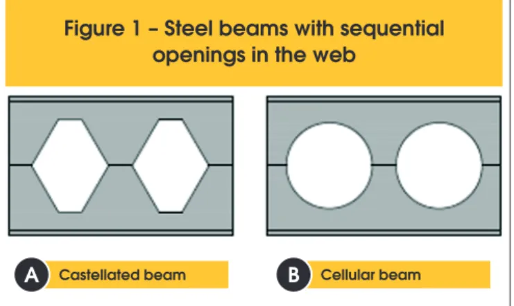
The steel beams with sequential openings in the web were created from structural requirements of weight reduction and are manufac-tured from rolled proiles, with standardized openings in the web. These beams are also referred to in the technical literature as “ex-panded web beams”. The openings in the web can be fabricated in the form of hexagons or circles, resulting respectively in castel-lated or cellular beams, Figure 1.
Cellular beams are made from I or H sections, whose web is cut lon -gitudinally in the desired format. Then, the two halves are displaced and welded by the axis, in order to generate openings in sequence along the web and increase in height of the cross section, Figure 2. The search for a rational use of resources in the design of structur-al steel buildings often induces the choice of solutions that facilitate the integration of services with the structure. Accordingly, the de-sign of steel beams with web openings for the passage of service ducts have been increasingly demanded. Cellular beams are quite used as they allow the passage of ducts through the openings, by integrating the facilities with the loor system, reducing the vertical space required per loor.
The cellular beam has represented a highly competitive solution. One of its great advantages is that with virtually the same amount of steel as the original beam, a much higher moment strength can be achieved, due the increased height of the cross section, mak-ing it possible to overcome longer spans, which will reduce the numbers of columns resulting in a lower cost and greater speed of erection. Even from an economic point of view, manufacturing operations have relatively little cost, and are compensated by in-creased load capacity and stifness.
In contrast to the advantages, the beams have reduced capacity to shear, which may require reinforcement of the web, generating signiicant cost. They are still ineicient in resisting the stresses resulting from localized forces, being more suitable for large spans subjected to small loads.
Cellular beams can be designed as composite when there is a shear connection between the steel and the concrete slab, thus being able to overcome even greater spans than the conventional
composite beam, due to the increased stifness provided by the geometry of the cellular beam.
Cellular beams are not used to their full potential for not being includ-ed in the national steel structure design standard, ABNT NBR 8800: 2008 [2] and also because they are unknown to most designers. This paper aims at the development of a computer program with the methods of Ward [3] and Lawson and Hicks [4] for the design of cellular composite steel and concrete beams, to analyze the inlu-ence of the cellular beam geometry on the ultimate load and failure mode of a series of cellular composite beams, constituted from the connection between the cellular steel proile and the composite slab. Additionally, the results obtained from the computer program for each method are compared with each other and with experi-mental results from the literature.
1.2 Failure modes
1.2.1 Formation of Vierendeel mechanism
The presence of shear forces of high magnitudes on the beam implies the formation of the Vierendeel mechanism (Figure 3 (a)). The formation of plastic hinges occurs at the corners of the openings, deforming the beam in the manner of a parallelogram-. This mechanism is more likely to develop in the beams with short spans, shallow tee-section and long weld between two openings.
Figure 1 – Steel beams with sequential
openings in the web
Castellated beam Cellular beam
A
B
The failure will occur at the opening with the maximum shear force. In the case of openings with the same shear force, this failure will occur at the opening with the greatest bending moment.
1.2.2 Formation of plastic hinges
This failure occurs when the bending moment makes the upper and lower tees yield by tension and compression. The moment strength is equal to the plastic moment of a section taken through the vertical centerline of an opening.
1,2,3 Rupture of the welded joint
The rupture of the welded joint occurs when the longitudinal shear stress exceeds the weld resistance (Figure 3 (b)). This failure
mode depends on the spacing of openings. There will be a greater chance of failure for smaller openings spacing.
1.2.4 Lateral torsional buckling
The lateral torsional buckling is characterized by a lateral displace-ment and a rotation of the cross section. According to Kerdal and Nethercot [6], the cellular beams and solid web beams have similar behaviors with regard to lateral buckling, but the geometric prop-erties of cellular beams should be taken in the centerline of the openings.
1.2.5 Web post buckling due to shear
The shear force VWP (Figure 4), acting along the welded joint stress
Figure 3 – Failure modes [5]
Rupture of the welded joint in a web post
B
Vierendeel mechanism
A
the web post in bending, causing tensile stress on contour AB and compression on the contour CD. In the web post buckling due to shear the compressed part tends to move away from the longitu-dinal plane of the section while the tensioned part tends to remain in the starting position. According to Kerdal and Nethercot [6], this failure mode normally occurs in inelastic regime with a signiicant yielding of the sections.
1.2.6 Web post buckling due to compression
Web post buckling due to compression occurs by the presence of localized loads or support reactions directly applied in the web post. It is similar to - buckling of axially compressed bars.
1.3 Methodologies for the design of cellular
composite steel and concrete beams
In this research were used two methods for the design of cellular composite steel and concrete beams, extracted from Ward [3] and Lawson and Hicks [4] design guides. Both design guides use the prescriptions of European standards when referring to limit states and design resistances already established. The formula-tions of the cited methods were adapted to meet the criteria of the ABNT NBR 8800: 2008. Items 1.3.1 and 1.3.2 briely describe the design strength for each ultimate limit state approached by these methods.
1.3.1 Lawson e Hicks [4] method
1.3.1.1 Shear strength at an opening
The shear strength of a cellular composite beam is established as the shear strength of the steel section plus the shear strength of the concrete slab. The shear plastic strength of the steel section at the opening is equal to:
(1)
w y pl,Rd a10.6A f
V
=
g
where
A
w is the sum of the areas of the upper and lower tee webs,f
y is the yield strength of steel andγ
a1 is the resistance factor of steel cross sections, equal to1.10
.For composite steel and concrete slabs, the shear force strength per unit length must be obtained according to the ABNT NBR 8800: 2008 [2]. For solid reinforced concrete slabs, the ABNT NBR 6118: 2014 [8] is used for the calculation of this shear strength. In both cas-es, the value of the shear force strength per unit length is multiplied by an efective width,
b
w, given byb
w=
b
f+
2
h
t ef, , whereb
f is the lange width of the steel section andh
t ef, is the efective depth of the slab. Regardless of the use of steel deck, the efective depth of the slab can be considered as 75% of its total depth (0.75ht).1.3.1.2 Moment strength at an opening
There are two diferent situations to determinate the plastic mo-ment strength. In the irst case it is assumed that the plastic neutral axis is in the slab, while in the second its location is admitted in the
top tee of the steel section. When the plastic neutral axis is in the slab, the moment strength is given by:
(2)
o,Rd bT,Rd ef T t
1
cM
N
h
z
h
z
2
æ
ö
=
ç
+
+ -
÷
è
ø
When the plastic neutral axis is in the top tee of the steel section, the moment strength is deined as:
(3)
o,Rd bT,Rd ef c,Rd T t1
cM
N
h
N
z
h
t
2
æ
ö
=
+
ç
+ -
÷
è
ø
where
N
bT Rd, is the axial force in the bottom tee,h
ef is the efec-tive depth of the beam between the centroids of the tees,h
t is the slab depth,z
T is the depth of the centroid of the top tee f r o m the outer edge of the lange,z
c is the depth of concrete in compres-sion eN
c Rd, is the compression strength of the concrete slab. 1.3.1.3 Vierendeel mechanismThe Vierendeel moment strength is the sum of the Vierendeel mo-ment strengths at the four corners of the opening, with the contribu-tion due to local composite accontribu-tion between the top tee and the slab. The Vierendeel moment strength must be greater than the design value of the diference in bending moment, due to shear force, at the left and right of the efective length of the opening, as given by:
(4)
b,NV,Rd t,NV,Rd vc,Rd Sd e
2M
+
2M
+
M
³
V l
where
M
b NV Rd, , is the reduced moment strength of the bottom tee for the presence of shear and axial tension,M
t NV Rd, , is thereduced moment strength of the top tee for the presence of shear and axial tension,
M
vc Rd, is the moment strength due to localcomposite action between the top tee and the slab.
The
V
Sd value is the design vertical shear force taken as the value at the lower moment side of the opening. For circular openings, the cal-culation method provides an equivalent rectangular opening, where its height is designated ash
eo=
0.9
d
o and its efective length is given byl
e=
0.45
d
o, on whichd
o is the diameter of the openings.1.3.1.4 Longitudinal shear strength
The design longitudinal shear strength of the web post can be es-tablished as:
(5)
o w ywp,Rd
a1
0.6s t f
V
=
g
1.3.1.5 Bending strength of web post
The design bending strength of the web post should be calculated using the elastic strength module as follows:
(6)
2 y o w wp,Rd a1f
s t
M
6
=
g
1.3.1.6 Web post buckling
To calculate the buckling strength it is necessary to determine the reduction factor (c) as established by ABNT NBR 8800: 2008 [2]. However, the non-dimensional slenderness of the web post is given by:
(7)
2 2 o o o w 11.75 s
d
t
+
l =
l
where
λ π
1=
Ef
y , on which E andf
y are the modulus of elas-ticity and the yield strength of steel, respectively. The buckling re-sistance of the web post is given by:(8)
o w y wp,Rd
a1
s t f
N
=
χ
g
1.3.2 Ward´s method [3]
1.3.2.1 Shear strength at an opening
The shear strength at an opening is taken equal to the shear
strength of the steel section, calculated by Equation (1). Therefore, the shear strength of the concrete slab is ignored.
1.3.2.2 Moment strength at an opening
The moment strength of a cellular composite beam can be deter-mined using a plastic stress distribution similar to that described in ABNT NBR 8800:2008 [2] for solid composite beams under posi-tive bending moment and full shear connection. In case of partial shear connection, the bending resistance of the cellular composite beam is given by:
(9)
(
)
Rd el i pl el
M
=
M
+ h
M
-
M
where
M
el is the elastic moment of the steel section (both tees),i
η
is the shear connection degree andM
pl is the plastic moment of the composite beam for full shear connection.1.3.2.3 Vierendeel mechanism
The Vierendeel mechanism occurs due the formation of a plastic hinge at a certain angle of the circular opening, at an associated section called critical section. The interaction of secondary mo-ments and axial forces, due to the transfer of shear and local axial force (caused by bending of the beam) through the opening is veri-ied using the following equation:
(10)
' '
Rd pl
N'
M' 1
N
+
M
£
where
N
'
eM
'
are forces on the critical section,N
Rd' is the product of the area of critical section by the yield strength of steel,y
f
, andM
'pl is the plastic moment in the critical section for plas-tic sections and equal to the elasplas-tic moment for other sections.1.3.2.4 Longitudinal shear force
The longitudinal shear resistance is calculated by Ward method [3] in the same way as shown for the Lawson and Hicks [4] method.
1.3.2.5 Web post lexural and buckling strength
The web post strength is governed by two modes of collapse: lexural failure, caused by the formation of a plastic hinge, and buckling. The failure mode depends on the web thickness and the ratio s/do
(spac-ing of adjacent open(spac-ings/diameter of open(spac-ings). After a series of non-linear inite element analysis, design curves were computed for the web post, which resulted in the following veriication equation:
(11)
2 max
1 2 3
e o o
M
C
s
C
s
C
M
d
d
é
æ
ö
æ
ö
ù
ê
ú
=
ç
÷
-
ç
÷
-ê
è
ø
è
ø
ú
ë
û
where
M
max is the maximum allowable moment at the section A-A of Figure 5 ,M
e is the elastic moment at the section A-A of Figure andC
1,C
2 andC
3 are constants deined according to the diam-eter of openings and web thickness.2. Methodology
2.1 About the program
The computer program for the design of composite cellular steel and concrete beams, called DIMCEL, was developed in MATLAB
(2010) addressing the Lawson and Hicks [4] and Ward [3] meth-ods. The program designs simply supported beams with compos-ite steel and concrete sections composed of symmetrical cellular sections, without web stifeners and unilled openings. Also allows the design of steel cellular beams, i. e., without considering the contribution of the concrete slab, but considers continuous lateral restraint. Therefore, both types of construction can be analyzed: unpropped construction and propped construction. In the case of unpropped construction, just perform additional veriication of the steel cellular beam subject only to construction loads.
Two types of concrete slabs are considered for the composite
Figure 6 – Geometrical characteristics of the cellular composite
beam from Oliveira [9] (dimensions in millimeters)
beam: solid concrete slab and composite steel and concrete slab. For shear connections, are addressed only stud shear connectors. The loads can be distributed along the length of the beam or con-centrated at pre-established locations by the user.
2.2 Program validation
For the program validation, were selected two numerical examples from the literature. Oliveira´s [9] example was used to validate the method of Lawson and Hicks [4] and Ward’s method [3] was vali-dated with the example contained in his own guide.
Oliveira´s [9] example corresponds to a cellular composite steel and concrete simply supported beam. The geometrical character-istics of the composite beam are shown in Figure 6. The cellular beam was obtained from an IPE 550 section. The steel is S235. Before the concrete cure the beam self weight is 7.35 kN/m, after the cure the self weight is 7.11 kN/m, permanent load is 3 kN/m and the imposed load is 15 kN/m. The compressive strength of the concrete is 30 MPa. The beam spacing is 2 m. Stud shear con-nectors were used with a diameter of 19 mm and two concon-nectors per trough.
The Ward’s [3] example corresponds to a cellular composite steel and concrete simply supported beam. The geometrical character-istics of the composite beam are shown in Figure 7. The cellular beam was obtained from an UB 457x67 section. The steel is S355. Before the concrete cure the beam self weight is 2.38 kN/m², after the cure the self weight is 2.24 kN/m², the permanent load is 0.5 kN/m² and the imposed load is 6 kN/m². The compressive strength of concrete is 30 MPa. The beam spacing is 3 m. Stud shear con -nectors were used with a diameter of 19 mm and one connector per trough.
Table 1 compares the results of the program with the numerical example of Oliveira [9], which addresses the Lawson and Hicks
[4] method and Table 2 compares the results of the program with Ward´s [3] method. The program validation was proven because it was found that the percentage diferences between program re-sults and numerical examples are due exclusively to the adopted normative criteria, since the program uses ABNT NBR 8800: 2008 while the examples have been resolved in accordance with Euro-pean standards.
2.3 Experimental testing
2.3.1 Nadjai et al. [10] test
The cellular composite steel and concrete beam, denominated Ul-ster Beam A1, was tested by Nadjai et al. [10] and corresponds to a simply supported beam with concentrated loads applied at two points. In Figure 8, the geometric characteristics of the experi-mental model are presented: span between supports of 4500 mm, expanded depth equal to 575 mm, diameter of the openings equal to 375 mm and spacing of adjacent openings of 500 mm. The steel cellular beam was fabricated from an UB 406×140×39 section. The steel is S355.
The composite steel and concrete slab has a width of 1200 mm and total depth of 150 mm, in which 99 is the depth of concrete above decking proile and 51 is the overall depth of decking proile, with normal density concrete. The concrete compressive strength was evaluated by three cubic samples during the test realization, which provided an average value of 35 MPa. The slab reinforce-ment consisted of welded wire mesh reinforcereinforce-ment A142 (bars with 7 mm diameter spaced every 200 mm) with yield strength of 500 MPa.
The ultimate limit state which led the Ulster Beam A1 to failure was the web post buckling. For comparison purposes, was calculated by the program the failure load related to that limit state by both
Table 1 – Comparison of the results obtained from
the Oliveira’s [9] example and the computer program
Bending at an opening (kNm) Shear force at an opening (kN)
Vierendeel mechanism
(kNm)
Longitudinal shear (kN)
MSd MRd Nab,sd Nab,rd VSd VRd Mv,Sd Mv,Rd Vwp,Sd Vwp,Rd
Example1 451.86 691.51 722.03 1104.97 162.31 390.74 29.22 58.95 131.8 225.9 Program2 451.88 625.05 726.21 1004.52 162.31 282.47 29.22 55.11 131.81 213.42 Difference (%) 0.00 9.61 -0.58 9.09 0.00 27.71 0.00 6.51 -0.01 5.52
Web post bending (kN)
Web post buckling (kN)
Limiting value of shear force (kN)
Deflection (mm) Buckling Bending
Mwp,Sd Mwp,Rd Nwp,Sd Nwp,Rd VSd VRd VRd
methods, Lawson and Hicks [4] and Ward [3]. From Table 3, it can be noted that both methods are safer and the method of Lawson and Hicks [4] predicted the failure load related to the limit state in question more accurately.
2.3.2 Müller et al. [11] test
The cellular composite steel and concrete beam, denominated
RWTH Beam 1B, was tested by Müller et al. [11] and corresponds to a simply supported beam with a concentrated load applied at four points. In Figure 9, the geometric characteristics of the ex-perimental model are presented: span between supports of 6840 mm, expanded depth equal to 555.2 mm, diameter of the openings equal to 380 mm and spacing of adjacent openings of 570 mm. The steel cellular beam was fabricated from an IPE 400 section. The steel is S355.
Figure 8 – Geometrical characteristics of the Ulster Beam A1 (dimensions in millimeters)
Table 2 – Comparison of the results obtained from the Ward’s [3] example
and the computer program
Bending at an opening (kNm)
Shear force at the support (kN)
Shear force at an opening (kN)
Longitudinal shear (kN)
Web post strength (kNm) MSd MRd VSd VRd VSd Vo,Rd Vo,Sd Vo,Rd MAA Mmax
Example1 504 808 201.6 1135 181.4 370 139 326 25 45.13
Program2 474.54 792.09 190.5 1031.7 171.45 373.29 131.14 329.18 23.61 41.02 Difference (%) 5.85 1.97 5.51 9.10 5.49 -0.89 5.65 -0.98 5.56 9.11
Vierendeel
mechanism Deflection (mm) NtT,Sd
+ Msd
Nt,RD Mpl
Example1 0.84 20.6
Program2 0.95 20.23
Müller et al. [11] considered full interaction between steel and crete. This interaction was achieved with the use of stud shear con-nectors, with a diameter of 19 mm and one connector per trough. The geometric characteristics of the steel deck are the same of that shown at Ulster-A1 model.
The composite steel and concrete slab has a width of 1800 mm and total depth of 130 mm, in which 79 is the depth of concrete above decking proile and 51 is the overall depth of decking proile, with normal density concrete. In the concrete slab was used a rein-forcement of 0.4% in longitudinal and transverse directions, which was located at 20 mm from top of the concrete face.
The cellular composite steel and concrete beam RWTH Beam 1B was tested with the openings 11 and 12 illed. The ultimate limit state that led the beam RWTH Beam 1B to failure was the web post buckling between the openings 1 and 2. From the calculation program results, the failure should be governed by the Vierendeel mechanism, with a load 21% lower than the experimental accord-ing to the Lawson and Hicks [4] method and a load 42% lower than the experimental according to the Ward´s [3] method.
The Table 4 shows the comparison between the experimental re-sults and computational program for each method considering the web post buckling that governed the experimental failure. It may be noted that both methods are safer and the method of Lawson and Hicks [4] was more accurate in the prediction of the failure load related to the limit state in question.
3. Results and discussions
The parametric study of cellular composite beams was performed considering beams obtained from two I rolled section, W 310x32.7 and W 530x85. The study was realized to simply supported beams subjected to a uniformly distributed load, considering propped con-struction. The steel is ASTM A572 (Grade 50).
The slab studied is composite steel and concrete with overall depth of decking proile equal to 75 mm, parallel to the beam span and composed of concrete with compressive strength of 30 MPa. The total height of the slab was 130 mm and the beam spacing was 3 m.
Table 3 – Comparison between the results
of Nadjai et al. [10] and the program
Failure load (kN)
Percentage difference (Pp* – Pe)/Pe x 100
Experimental (Pe) 370 –
Lawson e Hicks [4] 310 -16%
Ward [3] 276 -25%
(*) Pp = Failure load obtained by the program
Table 4 – Comparison between the results
of Müller et al. [11] and the program
Failure load (kN)
Percentage difference (Pp* – Pe)/Pe x 100 Experimental (Pe) 843.7 – Lawson e Hicks [4] 692 -18%
Ward [3] 556 -34%
(*) Pp = Failure load obtained by the program
Stud shear connectors with 19 mm diameter were adopted. Ini-tially, the number of connectors was calculated considering full interaction between steel and concrete for the solid composite beams that originated the studied cellular composite beams. The same number of shear connectors was adopted to the cellular composite beams.
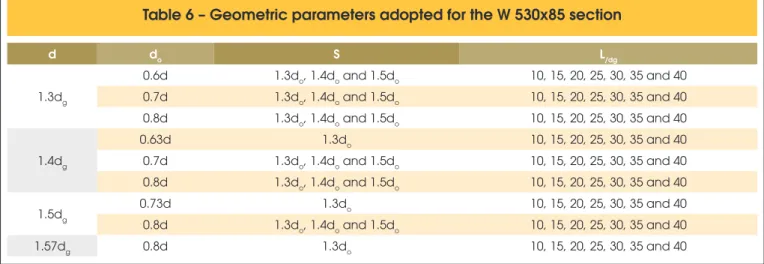
The Ward [3] and Lawson and Hicks [4] methods have different geometric limits for cellular beams. In this study, the geometric parameters of the beams have been defined according to the limits of both methods. Tables 5 and 6 show respectively the parameters and the ratio L/dg (span length/expanded depth)
adopted for the sections W 310x32.7 and W 530x85. The depth of the original solid beam was designated as dg, the diameter of the opening as do and the spacing of adjacent openings as s.
Initially, the composite beams were calculated with the original solid steel section, to determine its ultimate load (PVM) and the limit
state associated with the failure. Then, the program here devel-oped was used for the calculation of cellular composite beams and obtaining the ultimate load (PVC). Thus, the percentage diference
between the ultimate load of the cellular composite beam and the solid composite beam can be calculated as:
(12)
(
P
VCP
VM)
/ P
VM1 00 %
( )
d=
´
If the percentage diference is less than zero, it means that the solid composite beam resists better to the applied load than the cellular composite beam, otherwise the cellular composite beam performs better.
To determine the ultimate load for the solid and cellular beams, a routine was developed in the computer program which is able to increase the load value until it reaches the beam failure load, and then writing the value of the failure load and the failure mode in a spreadsheet. The veriication of the ultimate limit states was realized considering all applied loads (permanent and imposed loads) multiplied by 1.4. To verify the serviceability limit state of excessive delection, it was considered that 40% of the total load was permanent and, therefore, was used this portion of loading to calculate the long-term delection. The imposed load was taken as 60% of the total load, for the determination of its short-term delection.
Table 5 – Geometric parameters adopted for the W 310x32.7 section
d do S L/dg
1.3dg
0.6d 1.3do, 1.4do and 1.5do 10, 15, 20, 25, 30, 35 and 40 0.7d 1.3do, 1.4do and 1.5do 10, 15, 20, 25, 30, 35 and 40 0.8d 1.3do, 1.4do and 1.5do 10, 15, 20, 25, 30, 35 and 40
1.4dg
0.63d 1.3do 10, 15, 20, 25, 30, 35 and 40
0.7d 1.3do, 1.4do and 1.5do 10, 15, 20, 25, 30, 35 and 40 0.8d 1.3do, 1.4do and 1.5do 10, 15, 20, 25, 30, 35 and 40
1.5dg
0.73d 1.3do 10, 15, 20, 25, 30, 35 and 40
0.8d 1.3do, 1.4do and 1.5do 10, 15, 20, 25, 30, 35 and 40
1.57dg 0.8d 1.3do 10, 15, 20, 25, 30, 35 and 40
Table 6 – Geometric parameters adopted for the W 530x85 section
d do S L/dg
1.3dg
0.6d 1.3do, 1.4do and 1.5do 10, 15, 20, 25, 30, 35 and 40 0.7d 1.3do, 1.4do and 1.5do 10, 15, 20, 25, 30, 35 and 40 0.8d 1.3do, 1.4do and 1.5do 10, 15, 20, 25, 30, 35 and 40
1.4dg
0.63d 1.3do 10, 15, 20, 25, 30, 35 and 40
0.7d 1.3do, 1.4do and 1.5do 10, 15, 20, 25, 30, 35 and 40 0.8d 1.3do, 1.4do and 1.5do 10, 15, 20, 25, 30, 35 and 40
1.5dg 0.73d 1.3do 10, 15, 20, 25, 30, 35 and 40
0.8d 1.3do, 1.4do and 1.5do 10, 15, 20, 25, 30, 35 and 40
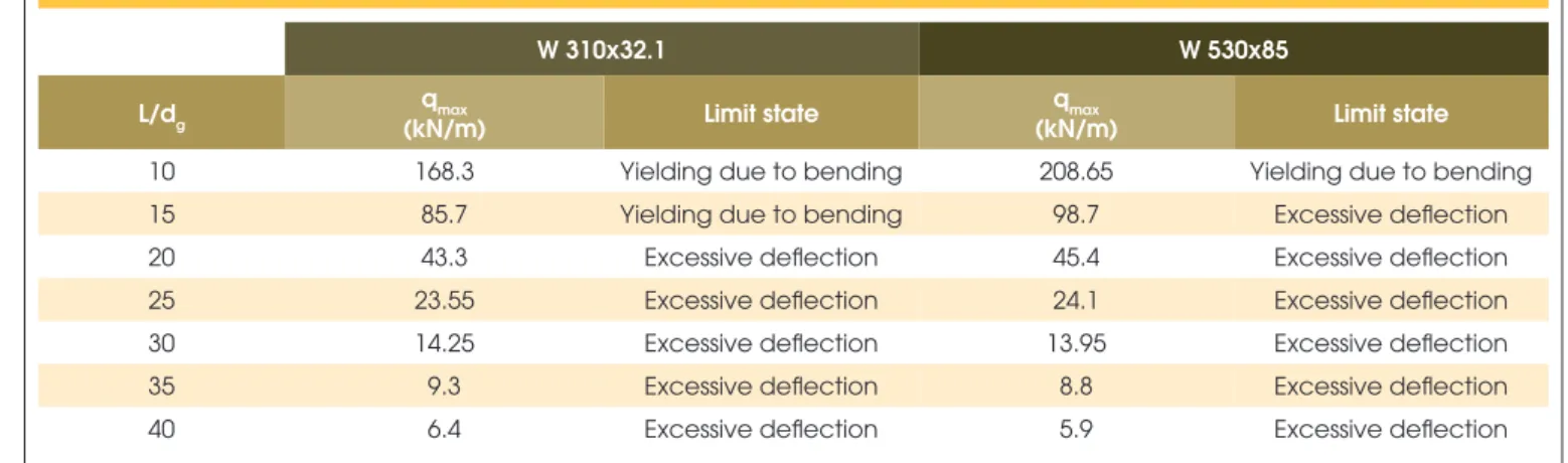
3.1 Solid composite beam designed
by ABNT NBR 8800:2008
Table 7 shows the limit state that governs the design of the solid composite beams for each ratio L/dg (beam span/depth of the solid
beam) and their associated ultimate loads.
3.2 Cellular composite beam designed
by the Lawson and Hicks [4] method
In the parametric study, the symbols for identiication of the cellular composite beams were given by the designation: VC dg - d/dg -
do/d - s/do - L/dg, where VC indicates cellular composite beam and
the variables dg, d , do, s and L are the geometric parameters. For
example, VC 310-1.3-0.6-1.3-10 means a cellular composite beam with 310 mm of depth of the original solid section, dg, the ratio between the expanded depth and the depth of the original section,
d/dg equal to 1.3, the ratio between the diameter of the opening
and the expanded depth, do/d equal to 0.6, the ratio between the
spacing of adjacent openings and the diameter of the opening, s/ do, equal to 1.3 and the ratio between the beam span and depth of
the original solid section equal to 10.
Table 8 shows the cellular composite beams obtained from a W
310x32.7 section that presented the best performance (higher resistance or lower delection, depending on the governing limit state) in relation to the solid composite beam. The limit state that governed the design is mentioned in the table.
At Table 8, it can be noted that the use of cellular composite beams obtained from the W 310x32.7 section is advantageous for L/dg
ratio equal or greater than 25, when the limit state of the solid com-posite beam is governed by the excessive delection and, thus, the services stresses are relatively low. It can also be noticed that the most adequate geometry for the cellular composite beams in this case is that with expanded depth equal to 1.5 times the depth of the original section, diameter of openings equal to 0.73 times the expanded depth and spacing of adjacent openings equal to 1.3 times the diameter of the openings.
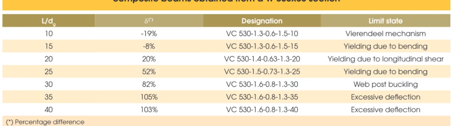
Table 9 shows the cellular composite beams obtained from a W 530x85 section that presented the best performance in relation to the solid composite beam. The limit state that governed the design is mentioned in the table.
At Table 9, it can be noted that the use of cellular composite beams obtained from a W 530x85 section is advantageous for L/dg ra-tio equal or greater than 20. It can also be noticed that the most adequate geometry for the cellular composite beams in this case is that with expanded depth equal to 1.5 times the depth of the
Table 7 – Limit state and ultimate load for the solid composite beams
W 310x32.1 W 530x85
L/dg qmax
(kN/m) Limit state
qmax
(kN/m) Limit state
10 168.3 Yielding due to bending 208.65 Yielding due to bending
15 85.7 Yielding due to bending 98.7 Excessive deflection
20 43.3 Excessive deflection 45.4 Excessive deflection
25 23.55 Excessive deflection 24.1 Excessive deflection
30 14.25 Excessive deflection 13.95 Excessive deflection
35 9.3 Excessive deflection 8.8 Excessive deflection
40 6.4 Excessive deflection 5.9 Excessive deflection
Table 8 – Ultimate load and associated limit state for cellular
composite beams obtained from a W 310x32.7 section
L/dg d(*) Designation Limit state
10 -29% VC 310-1.3-0.6-1.5-10 Vierendeel mechanism
15 -20% VC 310-1.3-0.6-1.5-15 Yielding due to bending
20 -8% VC 310-1.5-0.73-1.3-20 Web post buckling
25 13% VC 310-1.5-0.73-1.3-25 Yielding due to bending
30 32% VC 310-1.5-0.73-1.3-30 Yielding due to bending
35 48% VC 310-1.5-0.73-1.3-35 Yielding due to bending
40 66% VC 310-1.5-0.73-1.3-40 Yielding due to bending
Table 9 – Ultimate load and associated limit state for cellular
composite beams obtained from a W 530x85 section
L/dg d(*) Designation Limit state
10 -19% VC 530-1.3-0.6-1.5-10 Vierendeel mechanism
15 -8% VC 530-1.3-0.6-1.5-15 Yielding due to bending
20 20% VC 530-1.4-0.63-1.3-20 Yielding due to longitudinal shear
25 52% VC 530-1.5-0.73-1.3-25 Yielding due to bending
30 82% VC 530-1.6-0.8-1.3-30 Web post buckling
35 105% VC 530-1.6-0.8-1.3-35 Excessive deflection
40 103% VC 530-1.6-0.8-1.3-40 Excessive deflection
(*) Percentage difference
original section, diameter of openings equal to 0.73 times the ex-panded depth and spacing of adjacent openings equal to 1.3 times the diameter of the openings.
The analysis of the Tables 8 and 9 also shows a greater economic advantage in the use of cellular composite beams with greater depth, since the percentage diference between the ultimate load of the cellular composite beam and the solid cellular beam, d, is greater for W 530x85 section for all L/dg ratios. Also, it is noted
that the higher the L/dg ratio, the greater the percentage diference,
reaching more than 100% for the VC 530-1.6-0.8-1.3-35 and VC 530-1.6-0.8-1.3-40 beams, i.e., these beams have more than the double of the ultimate load of its corresponding solid-composite beams for the L/dg ratios equal to 35 and 40.
Table 10 shows the relation between the geometry of the cellular composite beam obtained from a W 310x32.7 section and the fail
-ure modes. It can be noted that yielding due to longitudinal shear occurs in small to medium spans (L/dg equal to 10, 15 and 20) in
beams with a small width of the web post, or in cases where the
s/do ratio is less than 1.4 and the do/dg ratio is less than 0.63. The
Vierendeel mechanism governed the design in cases of small to medium spans (L/dg equal to 10, 15 and 20), and the do/dg ratio equal to 0.8, that is, when the width of the web post was larger. For medium spans (L/dg equal to 20 and 25), the web post buckling
was predominant only for higher values of the expanded depth, i.e., d/dg ratio equal to 1.5 to 1.57. For large spans (L/dg equal to
30, 35 and 40), the critical limit states were yielding due to bending and excessive delection. However, the excessive delection did not occur for L/dg ratio equal to 30.
Table 11 shows the relation between the geometry of the cellular composite beam obtained from a W 530x85 section and the fail
-Table 10 – Relation between the geometry of the cellular composite
beam obtained from a W 310x32.7 section and the failure modes
Designation Limit state
Yielding due to longitudinal shear
L/dg≤15, do≤0.63d and s≤1.4do L/dg≤15, do=0.7d and s=1.3do L/dg =20, do≤0.63 do and s=1.3do
Web post buckling 15≤L/dg≤20, d=1.5dg and do=0.73d 20≤L/dg≤25 and d=1.57dg
Vierendeel mechanism L/dg≤15 and do≥0.7d, except in cases where occurred longitudinal shear L/dg=20 and do=0.8d
Excessive deflection
L/dg=40 and d=1.3dg L/dg=40, d=1.4dg and s≤1.4do L/dg=35, d=1.3dg and do=0.6d L/dg=35, d=1.3dg , do=0.7d and s=1.3do
Yielding due to bending
L/dg≥25 except in cases where occurred excessive deflection L/dg=20 and do≤0.7d, except in cases where occurred longitudinal shear
Table 11 – Relation between the geometry of the cellular composite
beam obtained from a W 530x85 section and the failure modes
Limit state Geometric parameters
Yielding due to longitudinal shear
L/dg≤15, do≤0.63d and s≤1.4do L/dg=15, do=0.7d and s=1.3do L/dg=20, do≤0.63d and s=1.3do
Web post buckling
L/dg≤20, d=1.4dg, do=0.7d and s=1.3do L/dg≤20, d=1.5dg and do=0.73d 20≤L/dg≤25, d=1.5dg, do=0.8d and s=1.3do
20≤L/dg≤25 and d=1.6dg
Vierendeel mechanism L/dg≤15 and do≥0.7d, except in cases where occurred longitudinal shear L/dg=20 and do=0.8d
Yielding due to bending
L/dg=15, d=1.3dg, do=0.6d and s=1.5do L/dg=20, do≤0.7d and s≥1.4do
L/dg=25 and do≥0.7d L/dg=30, d=1.4dg, do=0.8d and s=1.5do
L/dg=30,d=1.5dg and do=0.8d
Excessive deflection
L/dg>=35 L/dg=30 and do≤0.73d L/dg=30, do=0.8d and d≤1.4dg
L/dg=25 and do≤0.63d
ure modes. It can be noted that yielding due to longitudinal shear occurs in small to medium spans (L/dg equal to 10, 15 and 20) in
beams with a small width of the web post, or in cases where the
s/do ratio is less than 1.4 and the do/dg ratio is less than 0.63. The
Vierendeel mechanism governed the design in cases of small to medium spans (L/dg equal to 10, 15 and 20), and the do/dg ratio equal to 0.8, that is, when the width of the web post was larger. The web post buckling occurs in small to large spans (L/dg equal
to 10, 15, 20, 25 and 30), principally in beams with larger values of expanded depth, ie, d/dg ratio greater than or equal 1.5. Yielding
due to bending governed the design, mainly, in medium spans (L/ dg equal to 25), in beams with lower values of expanded depth, i.e., d/dg ratio less than 1.5, and do/d ratio greater than 0.63. For large
spans (L/dg equal to 35 and 40) the limit state of excessive
delec-tion always governed the design.
3.3 Cellular composite beam design
by Ward´s [3] method
Table 12 shows the cellular composite beams obtained from a W
Table 12 – Ultimate load and associated limit state for cellular
composite beams obtained from a W 310x32.7 section
L/dg d(*) Designation Limit state
10 -42% VC 310-1.3-0.6-1.5-10 Vierendeel mechanism
15 -28% VC 310-1.3-0.6-1.5-15 Vierendeel mechanism
20 -12% VC 310-1.3-0.6-1.5-20 Vierendeel mechanism
25 7% VC 310-1.5-0.73-1.3-25 Web post bending and buckling
30 20% VC 310-1.5-0.73-1.3-30 Excessive deflection
35 20% VC 310-1.57-0.8-1.3-35 Excessive deflection
40 19% VC 310-1.57-0.8-1.3-35 Excessive deflection
310x32.7 section that showed the best performance in relation to the solid composite beam. The limit state that governed the design is mentioned in the table.
At Table 12, it can be noted that the use of cellular composite beams obtained from a W 310x32.7 section is advantageous for
L/dg ratio equal or greater than 25. It can also be noticed that the
most adequate geometry for the cellular composite beams in this case is that with expanded depth equal to 1.5 or 1.57 times the depth of the original section, diameter of openings ranging from 0.73 to 0.8 times the expanded depth and spacing of adjacent openings equal to 1.3 times the diameter of the openings.
Table 13 shows the cellular composite beams obtained from a W 530x85 section that showed the best performance in relation to the solid composite beams. The limit state that governed the design is mentioned in the table.
At Table 13, it can be noted that the use of cellular composite beams obtained from a W 530x85 section is advantageous for L/dg
ratio equal or greater than 20. It can also be noticed that the most
adequate geometry for the cellular composite beams in this case is that with expanded depth ranging from 1.3 to 1.5 times the depth of the original section, diameter of openings ranging from 0.6 to 0.8 times the expanded depth and spacing of adjacent openings rang-ing from 1.3 to 1.5 times the diameter of the openrang-ings.
The analysis of Tables 12 and 13 also shows a greater economic advantage in the use of cellular composite beams with greater depth, since the percentage diference between the ultimate load of cellular composite beam and the solid cellular beam, d, is great -er for the W 530x85 section for all L/dg ratios. Also, it is noted that
the higher the L/dg ratio, the greater the percentage diference,
reaching more than 50% for the VC 530-1.6-0.8-1.3-35 and VC 530-1.6-0.8-1.3-40 beams.
Table 14 shows the relation between the geometry of the cellular composite beam obtained from a W 310x32.7 section and the fail-ure modes. It can be noted that the web post bending and buckling occurs in small to medium spans (L/dg equal to 10, 15, 20 and 25)
in beams with a small width of the web post, or in cases where the
Table 13 – Ultimate load and associated limit state for cellular
composite beams obtained from a W 530x85 section
L/dg d(*) Designation Limit state
10 -41% VC 530-1.3-0.6-1.5-10 Web post bending and buckling
15 -8% VC 530-1.3-0.6-1.5-15 Vierendeel mechanism
20 17% VC 530-1.3-0.6-1.5-20 Excessive deflection
25 41% VC 530-1.5-0.73-1.3-25 Excessive deflection
30 52% VC 530-1.6-0.8-1.3-30 Excessive deflection
35 52% VC 530-1.6-0.8-1.3-35 Excessive deflection
40 53% VC 530-1.6-0.8-1.3-40 Excessive deflection
(*) Percentage difference
Table 14 – Relation between the geometry of the cellular composite
beam obtained from a W 310x32.7 section and the failure modes
Limit state Geometric parameters
Web post bending and buckling
L/dg≤20, do≤0.7d and s=1.3do L/dg≤20, do=0.6d and s=1.4do L/dg≤25, do≤0.73d and s=1.3do
Vierendeel mechanism
L/dg≤25 and do=0.8d L/dg≤20, do=0.7 and s≥1.4do L/dg =30, do=0.8 and d≥1.4do
Excessive deflection
L/dg =25, d=1.3dg, do≤0.7d and s≥1.4do L/dg =25, d=1.3dg, do=0.7d and s=1.3do L/dg =25, d=1.4dg, do=0.7d and s=1.4do
L/dg =30 and do≤0.73d L/dg =30, do=0.8d and d=1.3dg
s/do ratio is less than 1.4 and the do/dg ratio is less than 0.63. The
Vierendeel mechanism governed the design in cases of small to large spans (L/dg equal to 10, 15, 20, 25 e 30), and the do/dg ratio equal to 0.8, that is, when the width of the web post was larger. For large spans (L/dg equal to 30, 35 and 40), the critical limit states
was the excessive delection.
Table 15 shows the relation between the geometry of the cellular composite beam obtained from a W 530x85 section and the failure modes. It can be noted that the web post bending and buckling occurs in small to medium spans (L/dg equal to 10, 15 and 20) in
beams with a small width of the web post, or in cases where the
s/do ratio is less than 1.4 and the do/dg ratio is less than 0.73. The
Vierendeel mechanism governed the design in cases of small to large spans (L/dg equal to 10, 15, 20, 25 e 30), and the do/dg ratio equal to 0.8, that is, when the width of the web post was larger. For
large spans (L/dg equal to 30, 35 and 40), the critical limit states
was the excessive delection.
3.4 Methods comparison
Figure 10 shows the comparison between the best performance ultimate load of the cellular composite beams obtained by both methods (higher strength or lower delection, depending on the limit state that governs the design) in relation to the solid com-posite beams. The analysis of Figure 10 shows that in most cases studied Ward´s [3] method shows more conservative results.
4. Conclusions
Two methods for the design of cellular composite beams were
Table 15 – Relation between the geometry of the cellular composite
beam obtained from a W 530x85 section and the failure modes
Limit state Geometric parameters
Web post bending and buckling
L/dg≤20, do≤0.7d and s=1.3do L/dg≤20, do=0.6d and s=1.4do L/dg=10, do=0.6d and s=1.5do
Vierendeel mechanism L/dg≤25 and do=0.8d
L/dg≤20, do=0.7 and s≥1.4do
Excessive deflection
L/dg=20, do=0.6d and s=1.5do L/dg=25 and do≤0.7d
L/dg≥30
studied: Ward´s [3] and Lawson and Hicks [4] methods. Both meth-ods use prescriptions of European standards when it comes to limit states and design strengths already established. In this work, an adaptation of the methods to conform with ABNT NBR 8800: 2008 [2] was carried out.
A computer program for the design of cellular composite steel and concrete beams addressing both cited methods was de-veloped in MATLAB (2010). The validation of the computer program was realized using two numerical examples available in the literature.
After the program validation, the adequacy of the methodologies has been veriied by experimental testing, comparing the results of the computer program with results of experimental tests available in the literature, namely, the results of Nadjai et al. [10] and Mül-ler et al. [11]. It was observed that both Lawson and Hicks [4] and Ward´s [3] methods showed slightly conservative results, however the Lawson and Hicks [4] method was more accurate in the predic-tion of the failure load.
Finally, a parametric study of cellular composite beams obtained from two laminated sections was conducted, W 310x32.7 and W 530x85. The study was realized for both methods presented, from which it was possible to obtain a number of conclusions about the calculation procedures:
n Both methods showed that the use of cellular composite beams
is advantageous when the L/d ratio is greater or equal to 20.
This was expected, since in these cases, what governs design of solid composite beams is excessive delection and the cel-lular beams present higher moment of inertia. It is worth not-ing that, in practice, the composite beams are used to achieve larger spans L/d≥25;
n Both methods showed a greater economic advantage in the use of cellular composite beams of greater depth, as the per-centage diference between the ultimate load of the cellular composite beam and the solid composite beam, d, was higher for the W 530x85 proile for all L/d ratios;
n The procedures proposed by Ward [3] for the veriication of
the web post buckling and bending, Vierendeel mechanism and excessive delection generated more conservative results, which made the Lawson and Hicks [4] method provide ultimate loads higher in all analyzed cases.
5. Acknowledgements
The authors would like to thank the institutions CNPq, CAPES, FAPES and PPGEC/UFES for their support in the realization of this research.
6. References
[1] PINHO, F. O. Vigas casteladas e celulares. Estruturas me-tálicas com mais resistência, menos deformação e redução de peso. www.arcorweb.com.br. 2009.
[2] ASSOCIAÇÃO BRASILEIRA DE NORMAS TÉCNICAS. NBR 8800: Projeto de estruturas de aço e de estruturas mis-tas de aço e concreto de edifícios. Rio de Janeiro, 2008. [3] WARD, J. K. Design of composite and non-composite
cel-lular beams, The Steel Construction Institute, 1990.
[4] LAWSON, R. M.; HICKS, S. J. P355: Design of composite beams with large web openings: in accordance with
Euro-codes and the UK National Annexes. Steel Construction In-stitute, 2011.
[5] TSAVDARIDIS, K.D.; D’MELLO, C. Behavior and Strength of Perforated Steel Beams with Novel Web Opening Shapes. Journal of Constructional Steel Research, v. 67, p. 1605-1620, 2011.
[6] KERDAL, D.; NETHERCOT D.A. Failure modes for castel-lated beams. Journal of Constructional Steel Research, p. 295-315, 1984.
[7] SILVEIRA, E. G. Avaliação do comportamento estrutural de vigas alveolares de aço com ênfase nos modos de colapso por plastiicação. Dissertação de Mestrado, Viçosa: UFV, 2011
[8] ASSOCIAÇÃO BRASILEIRA DE NORMAS TÉCNICAS. NBR 6118: Projeto de estruturas de concreto - Procedimen-to. Rio de Janeiro, 2014.
[9] OLIVEIRA, T. C. P. Vigas alveoladas: metodologias de di-mensionamento. Dissertação de Mestrado, Universidade de Aveiro, 2012.
[10] NADJAI, A.; VASSART, O.; ALI, F.; TALAMONA, D.; ALLAM, A.; HAWES, M. Performance of cellular composite loor beams at elevated temperatures, Fire Safety Journal, v. 42, p. 489-497, 2007.
![Figure 3 – Failure modes [5]](https://thumb-eu.123doks.com/thumbv2/123dok_br/18860746.417880/3.892.67.832.174.499/figure-failure-modes.webp)
![Figure 6 – Geometrical characteristics of the cellular composite beam from Oliveira [9] (dimensions in millimeters)](https://thumb-eu.123doks.com/thumbv2/123dok_br/18860746.417880/6.892.68.834.176.531/figure-geometrical-characteristics-cellular-composite-oliveira-dimensions-millimeters.webp)
![Table 1 compares the results of the program with the numerical example of Oliveira [9], which addresses the Lawson and Hicks](https://thumb-eu.123doks.com/thumbv2/123dok_br/18860746.417880/7.892.69.828.758.1113/compares-results-program-numerical-example-oliveira-addresses-lawson.webp)
![Figure 8 – Geometrical characteristics of the Ulster Beam A1 (dimensions in millimeters)Table 2 – Comparison of the results obtained from the Ward’s [3] example](https://thumb-eu.123doks.com/thumbv2/123dok_br/18860746.417880/8.892.69.830.225.536/figure-geometrical-characteristics-ulster-dimensions-millimeters-comparison-obtained.webp)
![Table 3 – Comparison between the results of Nadjai et al. [10] and the program](https://thumb-eu.123doks.com/thumbv2/123dok_br/18860746.417880/9.892.68.833.769.1132/table-comparison-results-nadjai-et-al-program.webp)