Universidade do Minho
Escola de Engenharia
João Mário Quintas Cunha
Fault Injection for the Evaluation of Critical
Systems
Universidade do Minho
Dissertação de Mestrado
Escola de Engenharia
Departamento de Informática
João Mário Quintas Cunha
Fault Injection for the Evaluation of Critical
Systems
Mestrado em Engenharia Informática
Trabalho realizado sob orientação de
Professor João Alexandre Saraiva
Acknowledgements
Along this academic path there were several people who helped and supported me so I could achieve my goals. Therefore, I would like to dedicate this section to thank the following people.
First of all, to João Saraiva, my supervisor from University of Minho, for his continued sup-port, encouragement and dedication. To Ricardo Barbosa, my supervisor from Critical Software S.A., for his technical support on fault injection, his help in integrating me in the company and his availability to answer all my questions. I am also thankful to both for their critical appreci-ation over my work and for helping me grow as a person and a professional.
To Critical Software for the opportunity to broaden my knowledge and be a part of a great work environment.
To my Co-Workers at Critical Software for all the sharing of knowledge, companionship, good environment and support.
To my Parents, Mário and Elisabete, for their help and support through both the good and bad times. Their love and dedication will never be forgotten.
To my Friends, who make my life outside of work so enjoyable, always having great times when we are together.
To my girlfriend, Carla, for all the patience, support and for always being by my side and helping me achieve my personal and my professional goals.
Resumo
Atualmente, os sistemas críticos estão cada vez mais presentes no nosso dia-a-dia, fazendo aumentar a necessidade de os assegurar cada vez mais e reduzindo o risco de acidente ou falha. A industria espacial e automóvel são exemplos de indústrias que usam esses sistemas e que necessitam de os ver assegurados. Consequentemente, têm de ser tomadas medidas para garantir a segurança de um sistema ao nível de software e hardware.
A injeção de falhas é uma das respostas a esse problema, fazendo uso das suas diferentes técnicas para poder avaliar e validar sistemas críticos. A injeção de falhas pode ser consider-ada uma técnica de teste ao software, onde as falhas podem ser injetconsider-adas ao nível do software ou hardware e cujos resultados podem ser monitorizados de forma a avaliar como é que o sistema reagiu a tais falhas. Scan-Chain Implemented Fault Injectioné a técnica de injeção de falhas que proporciona uma maior acessibilidade, observabilidade e controlabilidade. Com esta técnica, os níveis de hardware e de integração de sistemas podem ser validados.
O csXception® é um ambiente de injeção de falhas automatizado desenvolvido pela Criti-cal Software S.A para avaliar e validar sistemas críticos. A sua arquitetura é dinâmica e baseada em plug-ins de injeção de falhas. Devido à crescente presença dos microcontroladores ARM® Cortex-M3 na industria automóvel, surgiu a necessidade de criar um novo plug-in de injeção de falhas para o csXception®.
Assim, o objectivo principal desta dissertação de mestrado é o desenvolvimento de um novo plug-in de injeção de falhas para o csXception®, que permita injetar falhas em microcon-troladores ARM® Cortex-M3, contextualizar o novo plug-in com a norma ISO-26262 e utilizar um caso de estudo para mostrar alguns dos resultados obtidos.
Abstract
Nowadays, critical systems are much more present in our daily life, increasing the need to ensure that these systems are becoming safer and thus reducing the risk of accident or failure. The space and automotive industry are examples of industries who use these systems and need to see them insured. Therefore, actions need to be taken to guarantee the safety of a system, both at software and hardware levels.
Fault injection is one of the answers to that specific problem, making use of its different techniques in order to respond to the critical system validation and evaluation. Fault injec-tion can be considered as a testing technique, where faults are injected in the hardware or software levels and whose results are monitored in order to evaluate how the system handles such faults. Scan-Chain Implemented Fault Injectionis a fault injection technique that provides more reachability, observability and controllability. With this technique, the hardware-level and system-integration validation can be guaranteed.
csXception® is an automated fault injection environment that validates and evaluates crit-ical systems. Developed by Critcrit-ical Software, S.A., the csXception®'s architecture is dynamic and based on fault injection plug-ins. With the increasing presence of Cortex-M3 microcon-trollers on the automotive industry, a new plug-in for csXception® needs to be developed.
Thus, the main goal of this master dissertation is the development of a new fault injection plug-in for csXception® that allows the user to inject faults into ARM® Cortex-M3 microcon-trollers, to contextualize the new plug-in with the ISO-26262 safety standards and to use a case study to show some of the obtained results.
Contents
List of Figures . . . xv
List of Tables . . . xvii
List of Acronyms . . . xix
1 Introduction 1 1.1 Overview . . . 1
1.2 Critical Software S.A. . . 2
1.3 csXception® . . . 3
1.4 Document Structure . . . 3
2 Safety-Critical Systems and Fault Injection 5 2.1 Safety-Critical Systems . . . 6
2.1.1 Space Industry . . . 6
2.1.2 Automotive Industry . . . 8
2.2 Fault Injection . . . 11
2.2.1 Fault Injection History . . . 12
2.2.2 Fault Injection environment . . . 13
2.2.3 Fault Injection and ISO-26262 . . . 14
2.3 Fault injection techniques . . . 16
2.3.1 Hardware Implemented Fault Injection . . . 16
2.3.2 Software Implemented Fault Injection . . . 17
2.3.4 Robustness Fault Injection . . . 19
2.4 Fault Injection Tools . . . 19
2.4.1 csXception® . . . 19
2.4.2 GOOFI . . . 23
2.4.3 RIFLE . . . 24
3 Automated Fault Injection Plug-in 27 3.1 Objectives and Motivation . . . 27
3.2 Development Environment . . . 29
3.3 Fault Model . . . 30
3.4 Requirements Catalogue . . . 32
4 Automotive Plug-in Development 37 4.1 Architecture . . . 37
4.2 User Interaction . . . 40
4.2.1 Generate new Campaign . . . 41
4.2.2 Generate new Workload . . . 42
4.2.3 Configure CortexM3scifi plug-in . . . 42
4.2.4 Generate new Experiment . . . 44
4.2.5 Run Fault Injection . . . 49
4.3 Class Diagram . . . 52
4.4 Database Design . . . 54
5 Case-study: Anti-lock Brake System (ABS) 59 5.1 Case-study Description . . . 59
5.2 Architecture and Design . . . 60
5.3 Fault Injection Results . . . 63
5.3.1 Gold-Run . . . 63
5.3.2 Fault Injection 1 . . . 64
5.3.4 Fault Injection 3 . . . 66 5.3.5 Result analyzis and comparison . . . 67
6 Conclusion 69
6.1 Satisfaction on Goal Accomplishments . . . 69 6.2 Main Difficulties and Challenges . . . 71 6.3 Future Work . . . 71
List of Figures
1.1 Critical Software logo . . . 2
1.2 csXception® logo . . . 3
2.1 IEC-61508 decomposition . . . 9
2.2 ASIL risk estimation . . . 11
2.3 System failure behaviour . . . 12
2.4 Basic components of a fault injection environment . . . 13
2.5 Decomposition of the product development phases . . . 14
2.6 csXception® architecture . . . 20
2.7 EME (Screenshot) . . . 20
2.8 EFD source code trigger definition (Screenshot) . . . 21
2.9 EFD assembly code trigger definition (Screenshot) . . . 21
2.10 Xtract (Screenshot) . . . 22
2.11 The GOOFI architecture . . . 23
2.12 The RIFLE architecture . . . 24
3.1 Plug-in development environment . . . 29
3.2 Failure Mode . . . 31
4.1 CortexM3scifi Architecture . . . 38
4.2 LM3S9B90 Evaluation board . . . 39
4.4 CortexM3scifi Use-case diagram . . . 40
4.5 CortexM3scifi activity diagram . . . 41
4.6 Generate new Campaign . . . 41
4.7 Generate new Workload . . . 42
4.8 Configure CortexM3scifi - Debuggers Panel . . . 43
4.9 Configure CortexM3scifi - Communication Panel . . . 43
4.10 Generate Experiment - Basic information . . . 44
4.11 Generate Experiment - Workload, Timeout and Gold-Run . . . 45
4.12 Generate Experiment - Injection Runs . . . 45
4.13 Generate Experiment - Fault Location . . . 46
4.14 Generate Experiment - Fault Type . . . 46
4.15 Generate Experiment - Fault Trigger . . . 47
4.16 Generate Experiment - Access Before Trigger . . . 48
4.17 Generate Experiment - Access After Trigger . . . 48
4.18 Run Fault Injection . . . 49
4.19 Injection Run - Activity Diagram . . . 50
4.20 Fault Injection Process - Activity Diagram . . . 51
4.21 CortexM3scifi class Diagram . . . 52
4.22 Database Schema DTD . . . 54
4.23 XML code for CortexM3scifiWorkload table . . . 55
4.24 XML code for CortexM3scifiFault table . . . 56
4.25 XML code for CortexM3scifiFaultAccess table . . . 57
4.26 XML code for CortexM3scifiResults table . . . 57
4.27 Database Model . . . 58
5.1 Anti-lock Braking System . . . 60
5.2 Matlab-Simulink ABS model . . . 61
5.3 Gold-run - Velocity & Wheelspeed . . . 63
5.5 Fault Injection 2 - Velocity & Wheelspeed . . . 65
5.6 Fault Injection 3 - Velocity & Wheelspeed . . . 66
5.7 Results comparison - Vehicle speed . . . 67
5.8 Results comparison - Wheel speed . . . 67
List of Tables
2.1 Fault Injection mapping on ISO-26262 test activities . . . 15
3.1 Basic Fault Model . . . 31
3.2 REQ01 - Architecture compatibility with EME . . . 32
3.3 REQ02 - Architecture compatibility with EFD . . . 32
3.4 REQ03 - Architecture compatibility with Xtract . . . 32
3.5 REQ04 - Plug-in Configuration . . . 33
3.6 REQ05 - Storage Information . . . 33
3.7 REQ06 - Fault model definition . . . 33
3.8 REQ07 - Use of other software tools . . . 34
3.9 REQ08 - Use of third party Java libraries . . . 34
3.10 REQ09 - ABS case study . . . 34
3.11 REQ10 - Multiple fault triggers . . . 35
3.12 REQ11 - Generate new campaign . . . 35
3.13 REQ12 - Generate new experiment . . . 35
3.14 REQ13 - Generate new workload . . . 36
3.15 REQ14 - Run fault injection . . . 36
5.1 Fault Injection 1 - Details . . . 64
5.2 Fault Injection 2 - Details . . . 65
List of Acronyms
ABS Anti-lock Braking System
API Application Programming Interface
ASIL Automotive Safety Integrity Levels
CSW Critical Software
E/E Electrical and/or Electronic
ECU Electronic Control Unit
EFD Easy Fault Definition
EME Experiment Management Environment
FAM Fault Access Module
FDM Fault Definition Module
FI Fault Injection
FIM Fault Injection Module
GDB Gnu DebuGger
GOOFI Generic Object-Oriented Fault Injection
HWIFI Hardware Implemented Fault Injection
ICDI In-Circuit Debug Interface
ISO International Organization for Standardization
OpenOCD Open On-Chip Debugger
RISC Reduced Instruction Set Computing
SCIFI Scan-Chain Implemented Fault Injection
SCSs Safety-Critical Systems
SQL Structured Query Language
SWIFI Software Implemented Fault Injection
USB Universal Serial Bus
Chapter 1
Introduction
Summary
This chapter briefly exposes the context of this thesis: it gives an overview of the project, presents the company where the project was developed, and eventually shows the structure of the document.
1.1 Overview
Nowadays, the software industry needs to increase the levels of reliance of computer sys-tems. Aerospace, railway control, medical life-support, industrial plant control, nuclear power plants, automotive industry and the defense sector are just some of the areas imposing new challenges to software industries in terms of high availability, reliability and safety requirements. Additionally, mission-critical systems may be increasingly found in our daily life in areas such as the telecommunication industry, banking, insurance or any other industry that runs 24 hours a day and 365 days a year and where computer malfunctions can lead to tremendous capital losses.
In the last couple of years it became clear that the dependability requirements (Availability, Reliability, Integrity, Security) of computer systems cannot be guaranteed with only careful de-signs, quality assurances or fault avoidance techniques (Cotroneo, 2013). It is still unrealistic to assume that faults can be completely avoided. Along these lines, the true challenge
con-Chapter 1. Introduction
centrates on whether computer systems can provide the expected service in the presence of faults. Software systems developed in the areas discussed before need, indeed, to be tolerant to faults. This active area of research is known as Fault tolerance (Koren & Krishna, 2010).
To check whether a software system is either fault tolerant or not, the most straightforward approach is to inject faults in the said system. These faults can be injected at both hardware or software level. In an attempt to respond to market needs, Critical Software created csX-ception®, a product that automatically injects faults into multiple processor architectures' and software programming languages.
During my curricular internship at Critical Software S.A, it was my responsibility to develop a new fault injection plug-in for ARM® Cortex-M3 microcontroller running on csXcep-tion®. Even though the plug-in can run on any ARM® Cortex-M3 system its target area is the automotive industry, injecting faults on anAnti-lock Braking System(ABS) demonstrator and contextualizing the plug-in with the ISO-26262 automotive safety standard.
1.2 Critical Software S.A.
Critical Software(CSW) is a multinational Information Technology and Software company founded by Gonçalo Quadros (Chairman), João Carreira and Diamantino Costa. In 2011, CSW had a turnover of almost 20Me(twenty million euros). Today they have a Capability Maturity Model Integration (CMMI) with a Level 5 quality certification.
Figure 1.1: Critical Software logo
CSW was established in the year of 1998 in Coimbra (Portugal) starting as a spin-off of the University of Coimbra's business incubator and technology transfer center, the Instituto Pedro
1.3. csXception®
Nunes (IPN). Since then, CSW creates and deploys software solutions that guarantee support for key operational functions by delivering software tools that protect personnel, monitor the safety of equipment and ensures that critical processes are conducted securely and efficiently. Currently, the CSW has offices in Coimbra, Lisbon and Oporto (Portugal), Chicago (USA), Southampton (UK), São Paulo (Brazil), Maputo (Mozambique), Luanda (Angola) and Singapore (Singapore).
1.3 csXception®
The csXception® is an automated Fault Injection (FI) environment that uses advanced debugging and performance monitoring features existent on most modern processors to inject faults using software and monitoring their impact on the target system. Being developed since the mid-90s, it gave CSW the opportunity to work with the biggest aerospace agencies around the world, such as the National Aeronautics and Space Administration (NASA), the European Space Agency (ESA), the China Aerospace Science and Technology Corporation (CASC) and the Japan Aerospace Exploration Agency (JAXA) in order to validate their real time critical systems. csXception® offers solutions for different target systems with a consistent user interface. Moreover, it can always be improved by reducing the complexity of FI processes for different fault models and target systems.
Figure 1.2: csXception® logo
1.4 Document Structure
• Chapter 2: Describes the state of the art on fault injection and safety-critical systems, exploring the different techniques and tools used for this purpose;
Chapter 1. Introduction
• Chapter 3: Contains the description, motivation and details about the fault injection automotive plug-in;
• Chapter 4: Contains the development process implemented on the Cortex-M3 plug-in; • Chapter 5: Presents the results obtained from the ABS case study;
• Chapter 6: Finalizes the document with some conclusions, the satisfaction on ac-complishing the objectives and future work.
Chapter 2
Safety-Critical Systems and Fault
Injection
Summary
This chapter provides information for understanding the theoretical theme of fault injection, describing what is the motivation for its realization and which are its basic principles, and enumerating the various techniques and tools developed in this domain.
Being developed by humans, all software products are, consequently, prone to errors. As a result, programmers and hardware developers cannot predict everything and nothing is neither absolutely certain nor controllable. As such, when working with critical systems we must be aware of these variables because huge financial investments/impacts or human lives can depend on those systems.
Fault injection evaluates and validates critical systems, helping in the development process and giving additional information to the programmer by telling, for example, Where the bug is, How it happened and What could happen after that. Applying fault injection techniques to test critical systems will lead to a reduced failure probability.
In critical areas, such asSpace IndustryorAutomotive Industry, the financial investment is enormous and, consequently, their dependability on FI tools is increasing in order to guarantee a higher resilience for the systems.
Chapter 2. Safety-Critical Systems and Fault Injection
2.1 Safety-Critical Systems
A system is considered as safety-critical when the consequences of its failure can lead to the loss of a life or to significant property or environmental damage (Cotroneo, 2013).
Safety-Critical Systems(SCSs) are developed in several different domains and industries, for example, in transportation, space, telecommunications, military infrastructures (e.g. nu-clear and power plants) or medical control devices.
For each domain, SCSs are developed following a set of guidelines, specified on certifi-cation standards whose typical aim is to give recommendations about all the development process activities. For some safety-critical systems, these certifications are mandatory.
The software in such systems is much more complex. The need to perform more and more tasks and to guarantee interaction between them and the hardware equipment is becoming a real challenge. Even though the software is only one of the many parts of the SCSs, its quality assurance is the most difficult one. Although the SCSs Software is usually developed according with the most consolidate practices on software engineering, no methodology, tech-nique or strategy is currently able to assure the absolute absence of software failures. At this point, evaluation and validation of SCSs is crucial, guaranteeing that the SCSs Software and Hardware are developed according to safety standards.
2.1.1 Space Industry
The Space Industry refers mainly to the manufacturing of components that go into the Earth's orbit or beyond, such as satellites, launch vehicles and ground and mission control systems. The hardware manufacturing and software development of these components are carefully designed, documented and tested.
However, failures continue to happen. The most common in space is the single event upset (SEU), which is a change of state caused by ions and electro-magnetic radiation striking a sensitive node in a micro-electronic device, like in a microprocessor, a semiconductor memory, or power transistors. In Section 2.3 a possible solution to test and simulate these kind of
2.1. Safety-Critical Systems
errors/failures will be presented.
Horror stories where millions of dollars were lost already happened in space industry. We will present two of these stories next.
• In 1999, NASA lost communication with the Mars Climate Orbiter, sent to planet Mars in 1998. NASA lost 125 million dollars because a Lockheed Martin engineering team used English units of measurement while NASA's team used the more conventional metric system for a key spacecraft operation. According to the NASA report: "...The units' mismatch prevented navigation information from transferring between the Mars Climate Orbiter spacecraft team at Lockheed Martin in Denver and the flight team at NASA's Jet Propulsion Laboratory in Pasadena, California".
• In 2005, the DART Spacecraft incorrectly estimated the distance to the MUBLCOM satellite, leading to a crash and the total loss of DART after it used all its fuel. Ac-cording to the NASA report: "... a critical navigation failure occurred when the DART and the MUBLCOM spacecrafts were about 200 meters apart, which precluded the full activation of the AVGS (Advanced Video Guidance Sensor) and allowed DART to ap-proach MUBLCOM without accurate ranging information. A later failure of the collision avoidance system, which was relying upon inaccurate position and velocity information, allowed DART to ultimately collide with MUBLCOM at a relative speed of approximately 1.5 meters per second. Both spacecrafts survived the collision without apparent dam-age. Throughout the autonomous proximity operations, DART used its limited propellant faster than anticipated, which caused a premature end to the mission".
This kind of event, which was precluded by software failures, is a perfect example of sce-narios that can be strongly mitigated by the usage of fault injection techniques. Using FI and an adequate FI model, the potential failure could probably be detected and mitigated during development.
Chapter 2. Safety-Critical Systems and Fault Injection
2.1.2 Automotive Industry
Vehicles are part of our daily lives, whether we use them privately or in public transportation. Despite the growing environmental concern, vehicles are continuously increasing in numbers per capita in most countries. On average, the percentage of the cost of electronics embedded nowadays in automobiles can account already for about 40% of the overall cost. This value can be even higher in luxury models. Cars contain on average 30 to 50 Electronic Control Unit(ECU) and today's average cars contain about 10 million lines of code. It is expected that this number will grow up to 300 million in a decade (Economist, 2010).
As moreElectrical and/or Electronic(E/E) components are used within safety critical func-tions, safety has become a key issue for future automobile development. The most recent progresses in the areas of driver assistance, vehicle dynamics control, and active and passive safety systems increasingly touch the domain of safety engineering, as the failure of any of these systems can lead to the injury or death of people. Future developments on these areas will strengthen the need of safe system development processes, providing the possibility to generate evidences that all the system components are working as they should with maximum safety.
Situations where vehicles have to be recalled due to system or software issues have to be avoided at all costs. I will present two examples to demonstrate these types of problems:
• In 2010, Toyota Motor Sales (USA) announced the recall of approximately 2.3 million vehicles to correct sticking accelerator pedals on its 2009-10 RAV4, 2009-10 Corolla, 2009-10 Matrix, 2005-10 Avalon, 2007-10 Camry, 2010 Highlander, 2007-10 Tundra and 2008-10 Sequoia models. This issue is being partly attributed to a software glitch in the ECU control over the accelerator;
• In 2011, Honda issued a recall for 2.5 million CRV and Accord sedan due to a trans-mission software glitch.
2.1. Safety-Critical Systems
2.1.2.1 ISO-26262 standard
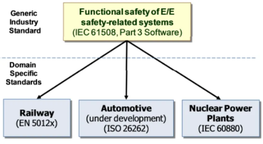
Since safety is a crucial aspect for road vehicles, the International Organization for Stan-dardization(ISO) prepared a new standard. ISO-26262, also entitled "Road Vehicles – Func-tional Safety", is a funcFunc-tional safety standard that defines funcFunc-tional safety for automotive equipment applicable throughout the lifecycle of all automotive electronic and electrical safety-related systems, going from the system's conception to the system's maintenance. This stan-dard is an adaptation of IEC-61508 (Figure 2.1) to comply with specific needs to the application of E/E systems within road vehicles.
Figure 2.1: IEC-61508 decomposition
ISO-26262 defines stringent requirements in order to increase the dependability and qual-ity of automotive safety critical systems. This is where fault-tolerant hardware and software mechanisms (e.g. robustness, fault isolation, detection, recovery, containment, monitoring, diagnostics, redundancy, etc.) are usually combined and used in order to guarantee (or at least improve) the safety of the system. It is hardly possible to test all those mechanisms on the system context without appropriate tools and without exercising all the operational con-ditions and situations, including the extreme/limit cases. These cases arise usually when hardware failures occur. When data is corrupted the software either falls into abnormal situa-tions, or has defects that get triggered, or result in very uncommon situations (e.g. the Honda CRV and Accord sedan recall). Fault injection techniques provide a way to cover and stimulate
Chapter 2. Safety-Critical Systems and Fault Injection
these extreme/limit or abnormal cases, depending on the realistic nature of the fault models produced and the capabilities offered by the tools to inject the faults and monitor the injection results.
With a trend of increasing complexity in software and hardware implementations, the inher-ent risks also increase, such as systematic failures and random hardware failures. ISO-26262 provides a set of practical requirements and processes to minimize these risks. ISO-26262 is only concerned with E/E systems, providing a framework within which safety-related systems based on other technologies can be considered. Some of the most important characteristics are:
• To provide an automotive safety lifecycle (management, development, production, op-eration, service and decommissioning) and to support the tailoring of the necessary activities during these lifecycle phases;
• To useAutomotive Safety Integrity Levels(ASIL) to specify the item's necessary safety requirements in order to achieve an acceptable residual risk;
• To provide requirements for validation and confirmation measures to ensure an accept-able level of safety.
ISO 26262 is intended to be applied to safety-related systems that include one or more E/E systems installed in passenger vehicles. Although until now only light passenger vehicles are mandated to comply with the standard, it is foreseen that in a near future all vehicles, including heavier ones, will also be mandated to abide with it.
One of the key concepts introduced by ISO-26262 is the ASIL. The hazard analyzis and risk assessment procedures (executed during the safety life-cycle) are based on the combination of the probability of exposure to the hazard, the possible controllability by the driver to the exposure to the particular hazard, and the possible outcomes if a critical event occurs (Figure 2.2). This combination determines the ASIL of a particular system item.
2.2. Fault Injection
Figure 2.2: ASIL risk estimation
The ASIL does not address the technologies used in the system as it is, purely focusing on the harm to the driver and other road users. Every safety requirement is assigned an ASIL classification of the scale A, B, C or D, with D being the most safety-critical level.
2.2 Fault Injection
Fault injection evaluates the dependability of a system, studying generated errors and failures. In complex systems it is hard to understand what causes some error/failures or where they begin. It deals with the calculated insertion of artificial faults into a target system or a simulation of it, in order to inderstand what could be the system's reaction to the injection of real faults and providing a feedback for system correction or enhancement, or for operational procedures' preparation (Hsueh, Tsai, & Iyer, 1997) (Carreira, Costa, & Silva, 1999).
FI has two main objectives:
• System validation: for testing the target system's fault-tolerance and verifying if it gives the expected service. If it does not occur, a bug must be reported and fixed. • System evaluation: to estimate the system's performance, providing information on
what kind of faults will occur and how frequently it will happen.
A system may not always behave as expected. The causes and consequences of these deviations from the expected function of a system are called "factors to dependability" or "fault-error-failure cycle" (Figure 2.3). (Ziade, Ayoubi, & Velazco, 2004) Each of these factors are described below.
Chapter 2. Safety-Critical Systems and Fault Injection
• Fault is a defect in the system (it can also be called "bug") that may or may not cause an error. For instance, although a system may contain a fault, the error is only triggered depending on specific input data.
• Error represents the difference between the expected and actual result in a software system. Errors are generated by a fault that changes the expected sequence of the software system.
• Failure happens when the system's behavior is different from the expected. For exam-ple, when an error occurs, if it is not caught and handled, the usage of fault tolerance techniques causes an unexpected behavior on the system and can be considered a failure.
Figure 2.3: System failure behaviour
When a fault causes an incorrect change in the target system an error occurs. Nevertheless, the fault remains localized in the target system and other errors may occur from that one. When a fault-tolerance mechanism detects an error it must handle the faults and hold the errors, otherwise a system failure may occur.
2.2.1 Fault Injection History
The fault injection technique appeared for the first time in 1972 in an article by Harlan Mills (Mills, 1972), describing a fault seeding approach (Voas & McGraw, 1998). The original idea was to estimate reliability based on an estimate of the number of remaining faults in a program. This estimation could be derived from counting the number of seeded faults that were uncovered during testing, in addition to counting the number of real faults that were found during testing.
2.2. Fault Injection
Initially applied to centralized systems especially dedicated to fault-tolerant computer ar-chitectures' in the early 70's, fault injection was used almost exclusively by industries for mea-suring the coverage and latency parameters of high reliable systems.
From the mid-80's, the academia started actively using fault injection to conduct experi-mental research. The initial work was mainly concentrated on understanding the error propa-gation and analyzing the efficiency of new fault-detection mechanisms.
In the early 90's, the foundation of fault injection was defined. More information and research in the way of literature can be found, with descriptions on how to employ fault injec-tion for hardware systems validainjec-tion, software testing and hardware design validainjec-tion (Benso & Prinetto, 2003). It was only in the late 90's that the first fault injection tools for system validation and evaluation made their appearances and one of them is the CSW's product: csXception®.
2.2.2
Fault Injection environment
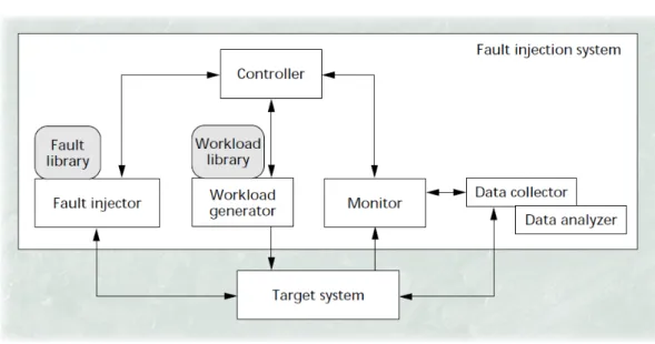
Figure 2.4: Basic components of a fault injection environment
In Figure 2.4 the basic components of a FI environment is represented. It usually includes a Target System, Fault Injector, Workload generator, Monitor, Controller, Data collector and a Data analyzer.
Chapter 2. Safety-Critical Systems and Fault Injection
• Target System is where the fault is going to be injected. It is typically running on a separate computer.
• Fault Injector is what injects faults in the target system. The fault library (also called fault model) is where FI techniques are specified, telling what is the fault type, location and trigger in use.
• Workload generator is usually an application/program that runs in the target system and contains its own libraries.
• Monitor receives the target system's outputs and communicates with the controller that decides which data is going to be saved in the Data collector.
• Controller is the main component of the FI system, setting all the FI flow. • Data collector saves the necessary data, generally in a database system.
• Data analyzer is the data processing analyzis, giving the user the necessary results to find what can be wrong with his system.
2.2.3
Fault Injection and ISO-26262
The main purpose of ISO-26262 is to ensure the safety of road vehicles by providing a set of guidelines to help product development. This functional safety standard divides the product's development process in three main parts (Figure 2.5): system level integration (part 4), hardware development (part 5) and software development (part 6).
2.2. Fault Injection
The ISO-26262 is the first standard to present fault injection as a highly recommended technique to be used at different critical levels. The purpose differs depending on the level where it is applicable. Table 2.1 shows the ASIL levels for each test activity of the ISO-26262.
ISO-26262 test activities ASIL classification
System Level (Part 4)
Correctness of implementation of system design specifications and technical safety requirements
B, C, D Effectiveness of diagnostic coverage of hardware fault detection
mechanisms
C, D Correctness of implementation of system design specifications,
technical and functional safety requirements
C, D Effectiveness of diagnostic failure coverage of safety
mechanisms at item level
C,D Correctness of implementation of functional safety requirements A, B, C, D
Effectiveness and failure coverage of safety mechanisms at vehicle level
C, D
Hardware Level (Part 5)
Hardware integration tests to verify completeness and correctness of the safety mechanisms' implementation
respecting hardware safety requirements
C, D
Software Level (Part 6)
Software unit testing D Software integration testing C, D
Table 2.1: Fault Injection mapping on ISO-26262 test activities
Based on this document we may conclude that fault injection is recommended for all the ISO-26262 test activities, namely for those with higher levels of criticality (C and D).
Even though ISO-26262 explicitly mentions the use of fault related approaches, the stan-dard does not detail the recommended fault injection approach to be used. This leaves room for various interpretations on how to approach this problem. Moreover, a correct fault model
Chapter 2. Safety-Critical Systems and Fault Injection
needs to be devised so that accurate fault injection can be performed.
2.3 Fault injection techniques
A fault injection application can act on different means, depending on what to validate and/or evaluate. The most common techniques are described next.
2.3.1 Hardware Implemented Fault Injection
Hardware Implemented Fault Injection(HWIFI) uses additional hardware to inject faults on a target system and examine the effects. Depending on the faults and their locations, HWIFI falls into two categories, HWIFI with contact or without contact (Hsueh et al., 1997).
2.3.1.1 Fault Injection with contact
Occurs when the injector has direct physical contact with the target system, producing voltage to the target chip. It is usually called pin-level injection because it interacts directly with the circuit pins of the processor. The two main techniques of pin-level FI are:
• Active probes, which add electric current to the target processor via probes presented on processor pins. However, we must be careful when using this technique because excessive amount of voltage on the board can damage it.
• Socket insertion, which makes the simulation of various physical faults possible by inserting a socket between the target hardware and its circuit board. The socket insertion injects stuck-at, open or more complex logic faults, giving total control to the processor's pin signals.
2.3.1.2 Fault Injection without contact
The injector has no direct physical contact with the target system, relying on an external source that produces a natural physical phenomenon (Hsueh et al., 1997), very similar to what
2.3. Fault injection techniques
happens to aerospace devices. Heavy-ion radiation, electromagnetic interference, weather conditions and temperatures are some of the examples of HWIFI without contact.
With heavy-ion radiation, an ion passes through the depletion region of the target device and generates current.
However, it is hard to tell the exact time or location at which the fault is going to be injected, since heavy-ion radiation and electromagnetic interference are not precisely triggered. (Cunha, Barbosa, & Silva, 2013)
2.3.2
Software Implemented Fault Injection
Software Implemented Fault Injection(SWIFI) is a low-cost and easy-to-control technique to inject faults in a target system, compared to HWIFI techniques described before (Arlat et al., 2003).
SWIFI is usually achieved by changing memory or registering values on the target system based on a defined fault model. It can be categorized based on when faults are going to be injected. There are two possibilities: during compile-time or during runtime.
2.3.2.1 Compile-Time Fault Injection
This method injects faults before the program's loading and execution. It injects faults directly into the source-code or assembly-code by emulating the hardware effect. This method implementation is very simple, but it does not allow the injection of faults as the workload program runs.
2.3.2.2 Runtime Fault Injection
During runtime injection, a mechanism is needed so the fault is injected on the target system. The most common ones are:
• Time-out - this is the simplest of all the techniques, as the trigger is obtained from a software or hardware time-out. Since it injects faults based on time, it produces
Chapter 2. Safety-Critical Systems and Fault Injection
unpredictable reactions on program behavior.
• Exception/trap - in this case, when a hardware exception or a software trap occurs, the workload control is passed on to the fault injector. A software trap is when a pre-determinate instruction in the code is reached, injecting the fault before the selected instruction. After that process the program resumes. Hardware exceptions can occur when a particular memory location is reached. Both mechanisms must be linked to the interrupt handler vector.
• Code Insertion - this mechanism inserts extra instructions, being the moment of injection the execution of those instructions.
2.3.3
Scan-Chain Implemented Fault Injection
Techniques for injecting faults in physical systems, such as HWIFI or SWIFI, provide limited controllability and observability. Moreover, these techniques may not be able to emulate the effects of all fault injections because they suffer from a lack of physical reachability (Folkesson, Svensson, & Karlsson, 1998).
One way of improving reachability as well as observability and controllability in the evalua-tion of physical systems is to useScan-Chain Implemented Fault Injection(SCIFI). Nowadays, all processors implement the IEEE 1149.1 standard. This standard defines test logic which can be included in an integrated circuit to provide standardized approaches to test the interconnec-tions between integrated circuits once they have been assembled onto a printed circuit board. The test logic consists of a boundary-scan register and other building blocks and is accessed through a Test Access Port (TAP).
The SCIFI technique injects faults, taking advantage of these boundary-scan chains and internal scan chains present in almost all mainstream developed processors.
2.4. Fault Injection Tools
2.3.4
Robustness Fault Injection
Robustness fault injection is oriented to a particular programming language (C, Java, Ada, etc.). The main objective of this technique is to analyze a given softwareApplication Program-ming Interface(API) for robustness weaknesses.
Typically, this API is a set of functions or routines that possesses a predefined set of pa-rameters of specific data types. If API papa-rameters are not validated when they are being called, the use of these incorrect parameters may lead to erroneous system behavior or even system hang or crash.
In order to assess such validation difficulties on API components, the methodology must be based on the characteristics of the API parameter types and correspondent bounds. For example, in a function composed by two parameters, each correspondingly integer and long data types, the values to be injected will be bounded by the maximum and minimum data values allowable by each data type.
2.4
Fault Injection Tools
Having presented fault injection techniques, we now present the different tools that imple-ment such techniques. In this Section, the focus is on the analyzis of the said tools' architecture, which use some of the techniques identified before.
2.4.1 csXception®
csXception® is a 100% JAVA application and may run in most operating systems, being Linux, Windows and MAC OS just a few among the options. In addition, it also uses the postgreSQL database system.
This product's architecture resembles to Client/Server type. The server side represents the host computer and the client side is the target system where the faults are going to be injected (Carreira, Madeira, & Silva, 1995) (Carreira, Madeira, & Silva, 1998).
Chapter 2. Safety-Critical Systems and Fault Injection
between these modules is made with Infobus, a Java communication class based on message exchange. The architecture of csXception® is shown in Figure 2.6.
Figure 2.6: csXception® architecture
csXception® is divided in four main modules:
• Experiment Management Environment (EME): front-end application that runs in the host computer and is responsible for the workload, campaign, experiment and FI definitions, execution and control. It provides a better user experience when interacting with the csXception® tool (Figure 2.7).
2.4. Fault Injection Tools
• Easy Fault Definition (EFD): allows EME to browse through the analyzed application source code and inter-actively mark memory ranges to set fault triggers (Figures 2.8 and 2.9).
Figure 2.8: EFD source code trigger definition (Screenshot)
Chapter 2. Safety-Critical Systems and Fault Injection
• Xtract: executes predefined queries onto the csXception® database and presents straightforward analyzis of FI experimental results (Figure 2.10).
Figure 2.10: Xtract (Screenshot)
• Injection Plug-In: defines the FI model. Changing this module will allow csXception® to adapt to a different target architecture. Currently, there are several available plug-ins with different FI techniques, particularly SCIFI, SWIFI and Robustness FI. Some examples of injection plug-ins developed by CSW are:
– ERC32SCIFI: SCIFI plug-in that runs in ERC32 architecture target systems. – LYNXPPC750: SWIFI plug-in that runs in PowerPC 750 architecture target
sys-tems.
2.4. Fault Injection Tools
2.4.2
GOOFI
Generic Object-Oriented Fault Injection(GOOFI) is a FI tool developed in JAVA and relies on aStructured Query Language(SQL) database for storing data. The main goal of GOOFI is to provide an easy way to adapt the new target systems or new FI techniques to the tool (very much like csXception®).
With GOOFI, when a new FI technique is added, a new FI algorithm must be implemented and the graphical user interface must be modified to support the new FI technique. (Aidemark, Vinter, Folkesson, & Karlsson, 2001)
Figure 2.11: The GOOFI architecture
GOOFI consists of a three-layered architecture (see Figure 2.11):
• Top-layer: Graphical User Interface(GUI), where all menus to create and run FIs are defined, giving a better user experience.
• Middle-layer: represents the tool Core, defining the FI model and the target system interface definition.
• Lowest-layer: represents the FI data storage and the communication with the Middle-layer and Top-Layer components.
Chapter 2. Safety-Critical Systems and Fault Injection
2.4.3
RIFLE
RIFLE is a pin-level FI tool developed in C++ under the Windows operating system. This tool can inject faults into a wide range of target systems and the faults are obviously mainly injected in the processor pins.
Figure 2.12: The RIFLE architecture
RIFLE's architecture (Figure 2.12) is formed by four modules. Three of them are hardware modules and the fourth one is for control and management, running only in the host computer: • Adaptation module: is the hardware part which contains the target processor and
the FI's electronic switches elements.
• Main module: contains the fault trigger hardware and the trace memory. The fault trigger activates a FI run when it reaches the expected conditions and the trace memory continuously saves the information in the target bus.
• Interface and Counters Module: establishes the interface between the RIFLE host and the other components.
2.4. Fault Injection Tools
• Control and Management Software: is the Core module. Manages the experi-ments' and fault's definitions, controls the FI sequence, validates fault definitions and collects relevant FI results.
This tool can inject faults in different target systems, being only required that the users change the adaptation module where the target architecture is defined (Madeira, Rela, Moreira, & J.Silva, 1994). Although different from the other tools presented before, the fault model must be the same, since its definition is centralized in the control and management software module.
Chapter 3
Automated Fault Injection Plug-in
Summary
This chapter shows what are the plug-in development motivation, objectives and requirements. Additionally, it gives an overview on all the high-level characteristics of the plug-in development.
3.1 Objectives and Motivation
As mentioned in Section 2.4.1, the csXception® tool can be adapted to different target architectures and techniques by implementing a fault injection plug-in which contains the fol-lowing levels of operations/information:
• Fault definition – it is composed by the plug-in's fault model implementation and infor-mation;
• Fault injection – it is responsible for all the fault injection process, namely the load and run of the workload. It is also responsible for the installation of the trigger, the fault and for collecting the debugger's output;
• Fault access – its main concern is the communication with the target system and the collection of the outcome from the injection run, either from theUniversal Serial Bus
Chapter 3. Automated Fault Injection Plug-in
Since Critical Software already developed other fault injection plug-ins there were some reusable artifacts to create this plug-in, mainly for the GUI forms and for the fault definition level.
On the fault definition level the target's architecture has to be defined and specified. In order to do so, the target's system documentation (system datasheet) has to be analyzed so all the memory location, where values can be read and written, can be accessed. However the changes were but a few, since the existing fault definition models were considered applicable. On the fault injection level the process has already been defined on other plug-ins (ex: run workload > install trigger > wait for trigger > inject fault > etc.), but since this one's debuggers are different from others used by other plug-ins and also has a different architecture, the com-munication between the fault injection plug-in and the target system debugger has different commands and instructions.
On the fault access level, the communication with the target system has to be fully de-veloped because the old communication process (Serial COM java library) had some timeout issues.
The target architecture of the automotive plug-in is based onReduced Instruction Set Com-puting(RISC) computer processors. This architecture provides higher performance because of its simplicity, which enables a much faster execution of each instruction, and because the set of instructions is smaller, making it less complex and propitious to errors. The target system used in this new fault injection plug-in is the ARM® Cortex-M3 microcontroller. The application of the Cortex-M family on automotive industry, particularly on systems with safety related func-tions (airbag, anti-lock braking, etc.), is widely used. An example of this trend is the Toshiba electrical vehicle motor control system, implemented by means of ARM® Cortex-M3 CPU cores and compliant with the ISO-26262 standard. (Cunha et al., 2013)
The fault injection technique implemented in this plug-in is SCIFI because, as explained in Section 2.3.3, it improves reachability and controllability, providing more accurate target system validations, while also obtaining better target system evaluation regarding observability. The plug-in's name is CortexM3scifi.
3.2. Development Environment
3.2
Development Environment
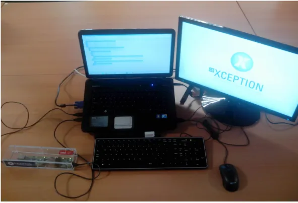
The Cortex-M3 fault injection plug-in is based on a host-targetenvironment and its aim is to inject faults on a physical target system using a SCIFI technique. Figure 3.1 shows the development environment of the Cortex-M3 plug-in on the Critical Software S.A office.
The target system (Cortex-M3 microcontroller and debugger) is on the left side of the figure, inside an acrylic case and connected via USB (micro-USB and mini-USB) to a Dell Vostro 1015 computer running csXception® with CortexM3scifi plug-in and PostgreSQL in Windows 7 operating system.
Chapter 3. Automated Fault Injection Plug-in
3.3
Fault Model
A Fault Model is a realistic engineering model of erroneous events that may occur in the construction, execution or operation of a system or system component. From this model, the system designer or user can predict the consequences of a particular fault and act upon it by making the system more robust. Typically, fault models are defined considering four dimensions (Location, Duration, Trigger and Type), each one with its own characteristics.
• Location: is where the fault will be injected: – Processor Register;
– Memory Address (Other processor register); – Flash Memory.
• Duration: is for how long the fault will be injected. In this project the duration of faults is one instruction cycle (e.g. the injection of an internal data bus fault during instruction fetch affects the bus during one memory access to fetch the next instruction). However, some faults may stay latent during several cycles (e.g. the fault injected on a general purpose register stays latent until the affected value is used in some calculation or a new value overwrites the same register);
• Trigger: is the dimension that defines when theFault Injectionwill occur:
– Instruction Access Trigger - This fault trigger occurs when an instruction that was fetched at a given memory address is at the pipeline execution stage;
– Memory Access Trigger - This fault trigger occurs when a memory address is accessed;
– Timeout Trigger - This fault trigger occurs when a timeout reaches its end. • Type: represents what the FI system will do when the time of injection comes, changing
3.3. Fault Model
– Bit Flip: is when one or more bits on the defined location are flipped;
– Reset Value: The value present in the fault location is overwritten with the reset value of that register or memory address;
– Specific Value: The fault location value is overwritten with another value defined by the user.
A basic fault model is presented in Table 3.1.
Location Duration Trigger Type
General Purpose Register #1 one clock cycle Instruction Execution Bit flip General Purpose Register #11 one clock cycle Memory Access Bit flip Program Status Register one clock cycle Instruction Execution Reset value On-chip Flash one clock cycle Timeout Trigger Specific value
Table 3.1: Basic Fault Model
In the automotive industry, for a fault to have proper meaning a domain knowledge is re-quired. This means that issues that occur at all levels of the product need to be known and understood. From this point on, a more accurate fault model can be devised and implemented. In the end, the failure modes can be mapped into the basic fault model and exercise/adul-terate the correct parts of the system as well as evaluate the behavior. This will compose a domain fault model (Figure 3.2).
Chapter 3. Automated Fault Injection Plug-in
3.4
Requirements Catalogue
The following list of requirements was defined as the starting point for the development of the Cortex-M3 plug-in. These requirements describe the functionality expected from the new plug-in for the csXception® and the main constraints that the Cortex-M3 plug-in should follow.
REQ01 - Architecture compatibility with EME
Type Non-Functional Status Mandatory
Priority High Difficulty High
The Cortex-M3 plug-in should be fully compatible with the software architecture of EME v2.3.
Table 3.2: REQ01 - Architecture compatibility with EME
REQ02 - Architecture compatibility with EFD
Type Non-Functional Status Mandatory
Priority High Difficulty Medium The Cortex-M3 plug-in should be able to provide the option to use the Easy Fault Definition (EFD) v1.0 module whenever the defined fault model needs it.
Table 3.3: REQ02 - Architecture compatibility with EFD
REQ03 - Architecture compatibility with Xtract
Type Non-Functional Status Mandatory
Priority High Difficulty Medium The data model of the Cortex-M3 plug-in should be compliant with the one defined for the Xtract v1.0 module. Any extensions developed will be independent from this module.
3.4. Requirements Catalogue
REQ04 - Plug-in Configuration
Type Functional Status Mandatory
Priority High Difficulty Medium The Cortex-M3 plug-in should be able to provide the user a configuration panel with board access information (COM port, bits per second, data bits, parity, stop bits and flow control) and executable debuggers (Gnu DebuGger(GDB) andOpen On-Chip Debugger(OpenOCD)).
Table 3.5: REQ04 - Plug-in Configuration
REQ05 - Storage Information
Type Non-Functional Status Mandatory
Priority High Difficulty Medium For data storage, the Cortex-M3 plug-in should use the database management functionalities provided by EME v2.3.
Table 3.6: REQ05 - Storage Information
REQ06 - Fault model definition
Type Functional Status Mandatory
Priority High Difficulty High
The Cortex-M3 plug-in must be compliant with the fault model detailed on section 3.3.
Chapter 3. Automated Fault Injection Plug-in
REQ07 - Use of other software tools
Type Non-Functional Status Mandatory
Priority High Difficulty Low
The Cortex-M3 plug-in should avoid using software tools other than the ones used by csXception v2.3 which are: Postgres database v9.2 and Java Runtime Environ-ment v7.
Table 3.8: REQ07 - Use of other software tools
REQ08 - Use of third party Java libraries
Type Non-Functional Status Mandatory
Priority High Difficulty Medium The Cortex-M3 plug-in must only use third party libraries that are under the GNU General Public License (GPL).
Table 3.9: REQ08 - Use of third party Java libraries
REQ09 - ABS case study
Type Functional Status Mandatory
Priority Medium Difficulty High The Cortex-M3 plug-in must inject faults in a case study based on an ABS simulator and analyze the results.
3.4. Requirements Catalogue
REQ10 - Multiple fault triggers
Type Functional Status Proposed
Priority Low Difficulty Medium
The Cortex-M3 plug-in should be capable of implementing multiple triggers per fault injection run. Example: After 5 seconds (timeout trigger), install an instruc-tion trigger.
Table 3.11: REQ10 - Multiple fault triggers
REQ11 - Generate new campaign
Type Functional Status Mandatory
Priority High Difficulty Low
The User should be able to generate campaigns.
Table 3.12: REQ11 - Generate new campaign
REQ12 - Generate new experiment
Type Functional Status Mandatory
Priority High Difficulty High
The User should be able to generate experiments.
Chapter 3. Automated Fault Injection Plug-in
REQ13 - Generate new workload
Type Functional Status Mandatory
Priority High Difficulty Medium The User should be able to generate workloads.
Table 3.14: REQ13 - Generate new workload
REQ14 - Run fault injection
Type Functional Status Mandatory
Priority High Difficulty High
The User should be able to run fault injection process.
Chapter 4
Automotive Plug-in Development
Summary
This chapter contains the details about the automotive plug-in development regarding the architecture, the class diagram and the database design. It also describes all user interactions/activities with the system.
4.1 Architecture
The csXception® is based on a Host/Target architecture (Figure 4.1) containing two differ-ent devices.
A Windows or Linux operating system is running on the host device, with a PosgreSQL database system and the csXception® execution environment that is responsible for four main components: EFD, EME, Xtract and Fault Injection Plug-in (CortexM3scifi Plug-in). The csX-ception® makes use of two debuggers (OpenOCD and GDB) to communicate with the target system through USB.
The target system is composed by two devices: ICDI board and LM3S9B90. The ICDI board is connected to the host device, allowing the user to control and access the Cortex-M3 microcontroller. The LM3S9B90 board contains the Cortex-M3 microcontroller and is also connected to the host device to collect the output from the fault injection process.
Chapter 4. Automotive Plug-in Development
Figure 4.1: CortexM3scifi Architecture
Host Computer
The Host Computer runs a PostgreSQL database server that establishes communication with csXception®. The csXception® comprises a front-end module which runs in a host com-puter and is responsible for the experiment's management/control (EME), an instruction trigger definition module (EFD), a data analyzis module (Xtract) and, finally, a fault injection plug-in that is responsible for the fault injection process that runs in the system under evaluation/val-idation, target output collector/monitor and the fault experiment definition.
The fault injection process uses a debugger execution environment with two components connected to the ICDI board (target debugger) through mini-USB. GDB is a debugger that al-lows intrusion on a software program while it is being executed (GNU, n.d.). But this is still insufficient. Since the program is being executed on an external physical system and the fault injection technique in use is SCIFI, an OpenOCD debugger is required to offer better control-lability and communications with the target system, as well as a boundary-scan testing using
4.1. Architecture
JTAG adapter. (OpenOCD, n.d.)
In order to collect the output from the program's execution on the target system we must use another component called Com_inC, with micro-USB connection. COM_inC establishes communication between the Host and the LM3S9B90 (Cortex-M3 microcontroller) by a Se-rial Communication (COM port) driver. The COM_inC component is a C developed executable (.exe) whose initial connection was made in JAVA with the "SerialComm.jar" component. How-ever, this library has known problems while disconnecting from the target system, causing a long wait time for each fault injection run.
Target System
The Stellaris EKS-LM3S9B90 Evaluation Kit is a low-cost platform for the evaluation of the LM3S9B90 board containing a Cortex-M3 microcontroller. The kit includes two boards: the LM3S9B90 Board and theIn-Circuit Debug Interface(ICDI) Board.
• EK-LM3S9B90: this board includes the ARM Cortex-M3 microcontroller, a 10/100 Mbit Ethernet port, a full speed USB 2.0 port and connectors for binding to the ICDI board:
– JTAG/SWD: allows JTAG or SWD connections, mainly used to debug and preform boundary-scan operations;
– PWR/UART: used to give 5V power and connect to the LM3S9B90 UART signals.
Chapter 4. Automotive Plug-in Development
• ICDI: this board is a USB full speed JTAG/SWD debugger board that includes a mini-USB connector so it can be rightly connected to an mini-USB port.
Figure 4.3: ICDI board
4.2
User Interaction
In order to properly understand the functioning of the CortexM3scifi plug-in it is important to represent the user interaction with the system.
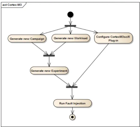
Therefore, in Figure 4.4 the use-case diagram of the Cortex-M3 plug-in is represented with five activities following a required order of events. Figure 4.5 shows the expected flow of events in order to correctly use the tool.
4.2. User Interaction
Figure 4.5: CortexM3scifi activity diagram
4.2.1 Generate new Campaign
A Campaign is a set of experiments that will run sequentially. The campaign generation is a form with three fields (Figure 4.6):
• Title, Author and Description.
Chapter 4. Automotive Plug-in Development
4.2.2
Generate new Workload
Workload is the binary file that will run on the target system when the fault injection process starts. The workload generation is a form with four fields (Figure 4.6):
• Title and Author;
• Executable File - Binary file that was flashed into the board;
• Source Code Path - Path to the .C files, which are necessary to use the EFD module.
Figure 4.7: Generate new Workload
4.2.3
Configure CortexM3scifi plug-in
The Configuration panel is managed by the EME module, even though every fault injection plug-in has a sub-section inside the"Targets"section.
The configuration window for the CortexM3scifi plug-in has two panels. First there is the
Debuggerspanel, which holds the necessary binary files to establish connection with the ICDI debugger board (Figure 4.3) and is divided in three fields:
• OpenOCD Location - Path to the binary file of the OpenOCD;
• OpenOCD Configuration File Location - Path to the OpenOCD configuration file; • Debugger Location - Path to the GDB binary file;
4.2. User Interaction
Figure 4.8: Configure CortexM3scifi - Debuggers Panel
Secondly there is the Target System Communicationpanel, which has all the necessary configuration properties to establish connection with the Stellaris LM3S9B90 board (Figure 4.2). Its aim is to obtain the output from the Cortex-M3 microcontroller in the fault injection process. The necessary fields are:
• COM Port - Port ID where the LM3S9B90 board is connected; • COM Port properties - Bits per second, Data bits, Parity, Stop Bits;
Chapter 4. Automotive Plug-in Development
4.2.4
Generate new Experiment
An Experiment is a sequence of fault injection runs separated by a target system reset and executed in an automated manner. The generation of the experiment is the most extensive process, being composed by 8 steps.
Step 1 - Basic information
In the first panel (Figure 4.10) the only mandatory field is the experiment title.
Figure 4.10: Generate Experiment - Basic information
Step 2 - Workload, Timeout and Gold-Run
The second panel (Figure 4.11) asks the user to select the workload used during the exper-iment execution and the timeout values associated with the gold-run execution that include:
• Gold-Run Checkbox - an execution of the workload without injecting any fault. The aim of the gold-run is to establish reference results;
• Timeout - chooses the workload timeout run based on the gold-run percentage time or precise time value (seconds, milliseconds or minutes);
4.2. User Interaction
At the top of the panel there is a table listing all the available workloads that have already been defined. Note that at least one workload must exist in order to define a new experiment.
Figure 4.11: Generate Experiment - Workload, Timeout and Gold-Run
Step 3 - Injection Runs
In the third panel (Figure 4.12) the user can define the number of injection runs he wishes to generate.
Chapter 4. Automotive Plug-in Development
Step 4 - Fault Location
The fourth panel (Figure 4.13) presents the available target locations where faults can be injected. These locations are separated by categories: Processor Registers, Other Registers and Flash Memory or SRAM.
Figure 4.13: Generate Experiment - Fault Location
Step 5 - Fault Type
The fifth panel (Figure 4.14) is the definition of the fault type. The user must choose one or more of the following types: Bit flip - which defines both the number of bits desired to flip and the related mask; or Reset Value and Specific Value.
4.2. User Interaction
Step 6 - Fault Trigger
The sixth panel (Figure 4.15) is the definition of the fault trigger. In this step the user must choose one or more of the following triggers:
• Instruction Access Trigger - defines the assembly instruction that will trigger the fault injection process. At this point, the EFD module can be used to help with the definition of the trigger, interpreting the source-code conversion to assembly;
• Memory Access Trigger - defines a memory location that will trigger the fault injection process, whether it be read or written in/from memory;
• Timeout Access Trigger - when the injection reaches a certain defined time, the fault injection process starts.
Chapter 4. Automotive Plug-in Development
Step 7 - Access Before Trigger
In the seventh panel (Figure 4.16) the user specifies which values the plug-in will save in the immediate time prior to the fault injection.
Figure 4.16: Generate Experiment - Access Before Trigger
Step 8 - Access After Trigger
In the eight panel (Figure 4.17), following the fault injection, the user specifies which values the plug-in will save and after which steps of the processor.