Universidade de Brasília
Instituto de Ciências ExatasDepartamento de Ciência da Computação
An Architecture to Support Control
Theoretical-based Verification of Goal-Oriented
Adaptation Engines
Ricardo Diniz Caldas
Dissertação apresentada como requisito parcial para conclusão do Mestrado em Informática
Orientador
Profa. Dra. Genaína Nunes Rodrigues
Brasília
2019
Ficha Catalográfica de Teses e Dissertações
Está página existe apenas para indicar onde a ficha catalográfica gerada para dissertações de mestrado e teses de doutorado defendidas na UnB. A Biblioteca Central é responsável pela ficha, mais informações nos sítios:
http://www.bce.unb.br
http://www.bce.unb.br/elaboracao-de-fichas-catalograficas-de-teses-e-dissertacoes
Universidade de Brasília
Instituto de Ciências ExatasDepartamento de Ciência da Computação
An Architecture to Support Control
Theoretical-based Verification of Goal-Oriented
Adaptation Engines
Ricardo Diniz Caldas
Dissertação apresentada como requisito parcial para conclusão do Mestrado em Informática
Profa. Dra. Genaína Nunes Rodrigues (Orientador) CIC/UnB
Prof. Dr. Vander Alves Profa. Dra. Cecilia Mary Fischer Rubira Universidade de Brasília Universidade Estadual de Campinas
Profa. Dra. Genaína Nunes Rodrigues
Coordenador do Programa de Pós-graduação em Informática
Agradecimentos
Em especial, agradeço aos meus pais, Lea e Ricardo, e meus irmãos, Gabriela e Leonardo, com os quais aprendi honestidade, humildade e resiliência, que foram fun-damentais na concepção deste trabalho. Agradeço também à orientadora e professora Genaína Rodrigues por proporcionar uma experiência acadêmica única e de excelência, que me levou ao encanto pela pesquisa. Por fim, agradeço aos colegas do laboratório (LES) e do departamento (CIC) pelas discussões e colaborações que encontram-se diluídas nas reflexões do presente trabalho, Arthur Rodrigues, Gabriela Solano, Gabriel Rodrigues, Léo Moraes, Gabriel Levi, Eric Gil, Samuel Couto, Jorge Mendes e tantos outros.
Resumo
Sistemas de software de longa vida devem evoluir e ser mantidos para lidar com as ne-cessidades flexíveis das partes interessadas, mudanças no ambiente e o comportamento in-certo dos componentes internos. Diversas abordagens na Engenharia de Software propõem aplicações de uso intensivo de software com recursos de autogerenciamento para superar as barreiras ao sucesso de sistemas intrinsecamente dinâmicos e complexos, com nen-huma ou pequena intervenção nen-humana. No entanto, a natureza da adaptação autonômica não é trivial, pois a combinação de todas as condições operacionais possíveis levaria a incalculáveis soluções baseadas em pesquisa para atingir o objetivo do sistema. O pro-cesso de projeto de software orientado a objetivos defende que colocar os objetivos do sistema como prioridade restringe as possibilidades de adaptação e fornece uma estru-tura direta que garante o comportamento confiável do sistema, orientando atividades de desenvolvimento, manutenção e evolução propensas a erros. O presente trabalho propõe uma contribuição para o processo de projeto orientado a objetivos de para sistemas auto-adaptativos, por meio do fornecimento de uma arquitetura para verificação de sistemas auto-adaptativos, que mapeia modelos de objetivos para o código executável do Robot
Op-erating System (ROS) executável sob a influência das incertezas. A etapa de verificação
é baseada na coleta de dados em tempo de execução e na análise de séries temporais, seguindo métricas da Teoria de Controle. Assim, os engenheiros de sistemas de software auto-adaptativos podem contar com evidências quantitativas para avaliar os mecanismos de adaptação com garantias de confiabilidade. A abordagem foi avaliada pela aplicação do processo de verificação em um mecanismo de adaptação orientado a objetivos, que adapta o comportamento de um sistema médico para melhorar a confiabilidade do sistema. Como resultado, a verificação forneceu informações sobre como melhorar o mecanismo em re-lação às suas configurações para combater o ruído sensores, levando a uma solução mais robusta.
Palavras-chave: Sistemas auto-adaptativos, Projeto de software orientado a objetivo,
Abstract
Long-lived software systems should evolve and be maintained to cope with flexible stakeholders’ necessities, changing environments and internal component’s uncertain be-havior. A large body-of-knowledge has been proposed for software-intensive applications with self-managing capabilities to overcome the barriers to the success of inherently dy-namic and complex systems with none or tiny human intervention. Nonetheless, auto-nomic adaptation nature is not trivial since the combination of all possible operational conditions would hinder infinite search-based solutions towards reaching the system’s goal. The goal-oriented software design process advocates that embracing the system’s goals as first-class citizens constrains the adaptation possibilities and provides a straightforward framework that guarantees the system’s trustworthy behavior by guiding error-prone de-velopment, maintenance and evolution activities. The present work proposes a contri-bution to goal-oriented design process of self-adaptive systems approaches by means of providing an architecture for verification of self-adaptive systems, which maps contextual goal-models to executable Robot Operating System (ROS) code that runs upon the influ-ence of uncertainties. The verification step is based on runtime data collection and time-series analysis w.r.t control theoretical based properties. Thus, engineers of self-adaptive software systems can rely on quantitative evidences to evaluate adaptation engines with guarantees of trustworthiness. The approach was evaluated by the use of the verification process upon a goal-oriented adaptation engine, which adapts the behavior of a medical system in order to improve the system reliability. As a result, our solution provided in-sights on how to improve the engine configurations for tackling the noise in sensing source of uncertainty, leading into a more robust engine.
Contents
1 Introduction 1 1.1 Motivation . . . 1 1.2 Research Challenges . . . 2 1.3 Research Contributions . . . 3 1.4 Evaluation . . . 3 1.5 Document Roadmap . . . 4 2 Theoretical Background 5 2.1 Self-Adaptive Software Systems . . . 52.1.1 MORPH reference architecture . . . 5
2.2 Control Theoretical Analysis . . . 7
2.3 Goal-Oriented Software Design Process . . . 10
2.3.1 Contextual Goal Modeling . . . 12
2.3.2 CGM to Parametric Formulae Transformation . . . 13
3 Our Approach 15 3.1 Introduction . . . 15 3.2 Knowledge Repository . . . 17 3.3 Analysis Layer . . . 18 3.3.1 Uncertainty Injector . . . 19 3.3.2 Runtime Verification . . . 20
3.4 System Manager Layer . . . 23
3.4.1 Adaptation Engine . . . 23
3.4.2 Strategy Enactor . . . 25
3.5 Mapping from Goal-Model to Components . . . 26
3.6 Target System Layer . . . 28
4 Case Study and Evaluation 30
4.1 Body Sensor Network a Case Study on ROS . . . 30
4.1.1 Knowledge Repository . . . 32 4.1.2 System Manager . . . 33 4.1.3 Target System . . . 35 4.1.4 Logging Infrastructure . . . 37 4.1.5 Analysis . . . 38 4.2 Evaluation . . . 39
4.2.1 Performing Control Theoretical Verification . . . 40
4.2.2 Providing Guarantees in the Presence of Uncertainty . . . 43
4.2.3 Threats to validity . . . 49
5 Related Work 51 5.1 Model-based Adaptation . . . 51
5.2 Guarantees under Uncertainty . . . 52
5.3 Control-based Metrics Analysis . . . 53
6 Conclusions and Future Work 55
List of Figures
2.1 Self-adaptive systems generic component architecture . . . 6
2.2 The MORPH reference architecture [20] . . . 6
2.3 Piano’s sound intensity response to unitary key press . . . 8
2.4 Input response with metrics . . . 10
2.5 Goal-oriented design process for SAS . . . 12
2.6 Contextual goal model example . . . 13
2.7 Software module execution behavior [9] . . . 14
2.8 Bottom-up formulae generation process [10] . . . 14
3.1 The process view . . . 16
3.2 The architecture . . . 17
3.3 System behavior and metrics . . . 21
3.4 Detailed vision of the adaptation engine . . . 24
3.5 Detailed vision of the strategy enactor . . . 26
3.6 Goal to component mapping example . . . 27
4.1 Body Sensor Network Goal Model . . . 31
4.2 Architectural view from the BSN implementation on ROS . . . 32
4.3 Exemplar activity diagram of data access . . . 33
4.4 Exemplar activity diagram of system manager . . . 34
4.5 Feedback Loop for Proportional Control . . . 35
4.6 Exemplar activity diagram of target system . . . 36
4.7 Configuration of markov chain for temperature data generation . . . 37
4.8 Exemplar activity diagram of injector . . . 38
4.9 Uncertainty injection signals . . . 39
4.10 Reliability behavior for tasks collection replication control . . . 42
4.11 Qualitative comparison between parametric formula and monitored behavior 43 4.12 Exemplify reliability formula response and sensitivity. . . 44
List of Tables
2.1 Behavioral metrics adapted from [18] . . . 9
2.2 Transformation definitions [24] . . . 11
4.1 Goal-Question-Metric definition . . . 40
4.2 Control theoretical metrics summary . . . 42
4.3 Summary of system’s response to noise in sensing injection . . . 46
4.4 System response to noise in sensing . . . 47
Chapter 1
Introduction
1.1
Motivation
Long-lived software systems should evolve and be maintained to cope with flexible stakeholders’ necessities, changing environments and internal components uncertain be-havior [1]. However, complex applications, inaccessible or dangerous environments and high cost of specialized human work places barriers on human-driven software adaptation. Therefore, Kephart J. et al. discussed the need to systematically address software sys-tems capable of autonomously adapting to runtime disturbances with none or tiny human intervention, the self-adaptive systems (SAS) [2]. Since then, a widely spread effort on producing approaches to enable modeling, development and maintenance of SAS has been placed [3, 4].
Nevertheless, tackling such dynamic needs is not trivial mostly due to uncertainties arising from multiple sources. First and foremost, uncertainty is an intrinsic property of unexplored scenarios in the software design phase, given those unpredictable events that arise at runtime, as well as error-prone requirements elicitation techniques, and unexpected situations that demand creative solutions [5]. Thus, reasoning on the impact of uncertainty on the system’s runtime behavior is fundamental for building trustworthy adaptation mechanisms in order to provide continuous goals achievement [6]. As a result, the reasoning process needs strict guidelines to assure that the end behavior follows high level rules that prevents the system from reaching any state that violates non-negotiable requirements (e.g. safety-critical applications) [7].
In order to help humans build trust in SAS, it is paramount to have goal-definition and visualization paradigms so that the specified goals do represent what is really desired [2]. For this reason, goals have become a first-class entity in SAS [8]. To recognize and manage uncertainties in the assurance process from early on, GORE (Goal-Oriented Requirements Engineering) offers proved means to decompose technical and non-technical requirements
into well-defined entities (goals) and reason about the alternatives to meet them. Hence, it has been used as a means to model and reason about the systems’ ability to adapt to changes in dynamic environments [7, 9, 10, 11, 12].
Thereby, it is noteworthy that the system goals continuous satisfaction is challenging, specially when the system operates under the presence of uncertainty [13]. This has been subject of research on the self-adaptive software engineering community in the last few decades [4, 14, 15, 16]. However, many of the proposed solutions lack on a strong theo-retical background for assuring the system dependability, what culminated on a research front that employs Control Theory for guiding the adaptation mechanisms design [8, 13]. After all, Control Theory provides a set of strong mathematically-based techniques which could guide the adaptation mechanisms design. In that sense control theoretical methods have been proposed [17, 18] to pave the way for performing trustworthy adaptation where the system goals are placed as first-class citizens.
1.2
Research Challenges
The assessment of uncertainty during the software design phase is vital for long-lived software systems. With that in mind, approaches rely on goal model verification [9, 10] to shorten the design-time and runtime gap by generating runtime models augmented with uncertainty from previously verified models in the light of model-checking. However, it is not sufficient to verify whether the system can reach the desired goal in the control-based mechanisms design process for SAS. With this in mind, we raise the first research question that we aim to address in this work.
How to ensure that the goal-oriented adaptation engine guarantees hold even when the system operates in the presence of uncertainty?
Goals have been used as a means to model and reason about the systems’ ability to adapt to changes in dynamic environments. However difficulties w.r.t eligible software system models, methodologies as well as architectures that pursue controllability as a first-class concern still remain. It is noteworthy that the contributions so far step forward into supporting the development of self-adaptive software, while they shorten the distance between design-time and runtime [6]. However they still lack on concrete architectures for evaluating whether the employed adaptation policies are in compliance with the control-theoretical requirements regarding the system’s reaction in face of unforeseen changes, i.e. uncertainty, during runtime. Then, we raise the second research question.
Can we conceive a concrete architecture for SAS that seamlessly integrates goal-oriented adaptation process and control theoretical verification while accounting for uncertainty?
To the best of our knowledge mRubis [19] is the only exemplar in SAS literature that supports the development, runtime evaluation and comparison between model-based adaptation techniques. Even though the approach may hinder scenarios execution for empirical validation of SAS, it would demand extra effort for integrating the proposed architecture to goal model specification language. Also, the metrics provided by the architecture are not compliant with control-theoretical guarantees. In addition, means are necessary to verify the system behavior following implemented and integrated adaptation engines [17]. Finally, we raise the third research question.
How to analyze the guarantees provided by goal-oriented adaptation engines from a control theoretical perspective?
1.3
Research Contributions
In a nutshell, our contributions pervades the research questions in three complemen-tary directions that summed up contribute to an end-to-end process from goal modeling to runtime verification. Thus, first we present a method that contributes with the assurance that the goal-oriented adaptation engine properties hold in the presence of uncertainty by providing means to exercise the system in a runtime environment with monitorable disturbance injection into uncertainty sources. Second, we conceptually propose a layered architecture that support the integration between goal-oriented adaptation process and control theoretical verification. And finally, we present a process for analyzing the guar-antees provided by adaptation engines from control theoretical perspective, that stands upon timeseries analysis. As a minor contribution, we provide an exemplar of SAS for empirical validation.
1.4
Evaluation
We evaluate our work by collecting evidence to our claim that the proposed architec-ture supports the verification of guarantees provided by goal-oriented adaptation engines from a control theoretical perspective. In two sequential experimental sets in which we evaluate whether the goal-oriented model and the analysis algorithm provide enough in-formation for a sound control theoretical analysis of the system behavior and whether an assurance process based on the model may lead the system into ensuring the desired
prop-erties even when operating under uncertainty. All upon an architecture for self-adaptive systems following which a Body Sensor Network prototype is implemented, where we monitor and adapt individual components parameters for ensuring a reliable system. For the first, the results show that the relative error between the goal-oriented model and the monitored behavior w.r.t control theoretical metrics are sufficiently acceptable, but more investigation could be placed on the model’s sensitivity in respect to the terms contri-bution to its global state. In addition, results derived from the second experimental set assert that the approach enables a sound verification of the system behavior under influ-ence of the goal-oriented adaptation engine even in presinflu-ence of noise in sensing, source of uncertainty, towards guaranteeing continuous fulfillment of the desired system goals. Summed up, our evaluation efforts build evidence that our runtime verification architec-ture seamlessly contributes to the goal-oriented SAS design process.
1.5
Document Roadmap
The rest of the document is organized as follows. Chapter 2 provides further detail on the theoretical foundations necessary for the proposal explanation. Chapter 3 details the approach that tackles the claimed research questions. Chapter 4 discusses the prototype implemented and the experimental scenario employed in the work along with the results. Conclusions about the work itself and future work are presented in Chapter 6.
Chapter 2
Theoretical Background
2.1
Self-Adaptive Software Systems
Continuous behavior change is a basic necessity for long-lived software systems, since stakeholders’ needs can be volatile, operating environments be dynamic and the system’s internal structure, hardware and/or software, may degrade in time. However, change might lead to unwanted behavior if not performed with caution, to address that, many software engineering techniques (e.g. BDD, TDD, refactoring, etc) have been proposed for human-driven adaptation. Though, strict needs on the behavioral change may un-able human-driven change such as budget availability, unreachun-able environments, time constraints for performing software adaptations. Self-adaptive software engineering have been studied to address this issue by enabling systems to adapt themselves with tiny or none human intervention. When it comes to the self-adaptive system high-level archi-tecture, it’s well-established that the participating entities are organized into managing system, managed system and environment, see Figure 2.1.
A long list of studies [3][4] on how to develop autonomous software systems from a wide variety of perspectives have been published in the last twenty years right after the seminal work of Kephart and Chess [2] which proposed a first version of the MAPE-K adaptation loop architecture. Among all, we have decided to deepen the study on the MORPH reference architecture [20] since a hierarchical multi-layer which fits well with goal-oriented approaches is proposed, which is the core of this work.
2.1.1
MORPH reference architecture
The MORPH reference architecture for self-adaptive systems, proposed by Braberman V. et al., provides a four-layered architecture in which adaptation reasoning is divided in two perspectives, reconfiguration and behavioral. The dynamic reconfiguration stands
Figure 2.1: Self-adaptive systems generic component architecture
for runtime changes of component structure and operational parameters in order to guar-antee non-functional requirements such as the ones comprising dependability [21] (e.g. reliability, availability, security). On the other hand, behavioral update guides the system behavior to ensure that high-level goals are satisfied and is taken as more of an orchestra-tion of the system components. A representaorchestra-tion of the proposed architecture is depicted in Figure 2.2.
The Goal Management layer encompasses the highest level management reasoning processes of the architecture. In which, a Goal Model Manager triggers reconfiguration or behavior problem solvers for determining solutions in respect to strategies that satisfy the target system goals. This layer interacts with a Knowledge Repository from which the goal models, for example, are extracted, as well as with the Strategy Management layer by, within a feedback loop fashion, sending new strategies resolutions and receiving exceptions that are seen as constraints towards finding acceptable strategies.
Then, the Strategy Management layer is responsible for triggering adaptations to changes that can sufficiently be addressed by pre-processed strategies, the ones synthe-sized by the Goal Management layer. The main concept of the layer is to permit quick adaptation in face of not attending runtime strategies. It receives adaptation requests from the Strategy Enactor layer and replies it with a deployable strategy. However, when no strategy suffices the constraints imposed by the lower layer, it must throw an exception to the Goal Management layer. There also is internal information exchange in between the behavior and reconfiguration managers to ensure consistency in the strategy selection. Further into the architecture, the Strategy Enactor layer involves the target software system constant monitoring and triggering either behavioral or reconfiguration operations thus guiding the system towards the strategy’s goals. It directly interacts with the sys-tem’s sensors and actuators. In case of unsolvable adaptations regarding the syssys-tem’s state, exceptions are thrown to the upper layer.
A logging mechanism is recommended in between the Strategy Enactor layer and the target system, it can collect information regarding the system states during the execution and the adaptations triggered. This information can be further treated and interpreted to refine the models within the Knowledge Repository. At last, the Target System layer, that contains the components that execute the system to satisfy the stakeholders’ needs. It is necessary that the target system provides mechanisms for state monitoring and either reconfiguration and/or behavioral actuation.
2.2
Control Theoretical Analysis
Control systems are subject to inputs not known at design-time, based on that, they are designed to respond within acceptable boundaries to dynamic environmental inter-actions. The analysis on whether the designed system is operating accordingly demands metrics that can be used for comparison in respect to the performance of various control systems [22]. Design-time analysis methods mainly consist on stressing a model of the system with known input signals and initial conditions variations, and collecting its re-sponse in terms of the properties to be evaluated, then the metrics that correspond to the
response behavior are calculated and can be used for further comparison. This section details the analysis of typical second order responses and presents the metrics employed throughout the work.
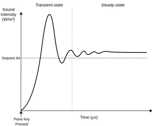
When mechanical systems are affected by an input, the amount of energy contained varies and it responds by sparing the received energy towards the equilibrium. The energy dispersion can be realized by movement, emission of sounds or release of heat, for example. Then, suppose a piano key that, when pressed, unleashes a hammer that hits a stretched string, that produces sound to disperse the kinetic energy transferred to it. So, once the piano key is pressed and released the piano responds with a sound with an intensity proportional to the force applied by the pianist to the key. Now, suppose that the pianist desires that the sound intensity be around 64W/m2, characterizing the setpoint. He or
she, then, presses the intended piano key with a correspondent force producing the curve depicted in Figure 2.3.
Figure 2.3: Piano’s sound intensity response to unitary key press
The transient portion of the curve is defined by the moments before the sound in-tensity stabilizes nearby the setpoint value, according to the commonly used stability criterion, the system response stabilizes when it converges to a certain value [22]. When the curve is within the stability region, it is said to have achieved the steady-state. The Control Theory community, specifically for transient and steady-state analysis [22][18]
defined metrics to classify and compare responses to inputs be them known (forecasts) or unknown (disturbances). In this work, they are presented in Table 2.1.
ID Metric Description
M1 Stability “Ability of the system to achieve its goals”
G1
M2 Settling time “The time required to reach the setpoint boundaries after a goal change”
M3 Overshoot “Spikes in the system output for different adapta-tion opadapta-tions”
M4 Steady-state error “Oscillations in the response time of the soft-ware for different adaptation options”
M5 Control effort “The amount of resources consumed by the ad-aptation mechanism to achieve goals”
G2 M6 Robustness
“Deviations in the system output under disturb-ances”
M7 Optimality “The tasks completed and the resources used by the software for different adaptation options”
Table 2.1: Behavioral metrics adapted from [18]
The metrics M1 - M4, grouped by G1, are related to transient and steady-state aspects of the runtime behavior of the system and the M5 - M7, grouped by G2, are related to the controller properties on whether it can optimally adapt to specific situations and is robust enough in face of uncertain scenarios. Where, G1 stands for ‘Input Response’ and G2 to ‘Controller Property’. Formal means of evaluating the metrics in respect to the mathematical models that represent the controller, the system plant and the control loop topology applied to each case are placed. However, white-box approaches are not valid in the scope of the work since it is claimed that not known a priori control algorithms are evaluated through the analysis.
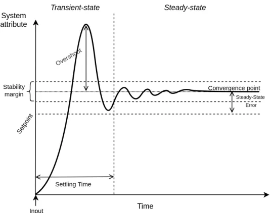
The input response analysis does not comprise the whole collected execution life-cycle, since more than one inputs can be taken during an analysis experimental set. Therefore it is defined that the response itself begins at the instant that the input is observed until a few moments after the system stabilization or another input is taken. See Figure 2.4. On the other hand, the controller property analysis takes into consideration both, the complete period of simulation execution. In contrast to the input response, the controller properties analysis is related to the amount of computational resources demanded, its capacity of dealing with uncertain scenarios and whether the adaptation decisions leads the system to an optimal behavior.
Figure 2.4: Input response with metrics
2.3
Goal-Oriented Software Design Process
The goal-oriented requirements engineering (GORE) has been an active field of study for the last two decades, in which goals are taken as first-class citizens [23]. Typically, GORE approaches advocates the use of goal models for elicitation, conceptualization and analysis of the system requirements, in which, interactions between the system’s and environment’s entities collaborates positively or negatively for the stakeholders’ needs satisfaction. Despite that, approaches that not only employs goal models for creating and reasoning, but, for the entire life cycle (e.g. architecture, process design, coding, testing, adaptation, evolution) have been extensively proposed [24], with the advantage that the system operations continuously meet the goals it was designed or adapted for.
Using goal models in the entire life cycle of the application demands trustful trans-formations, mappings or integration from source, goal model, to the target, which corre-sponds to the artifact to be used in one or more phases of the software design or runtime. Horkoff J., et. al [24] performed a meta-study on the literature regarding transformations from/to goal models that pervades the entire life cycle of software systems. In which a classification of the transformations is placed. This work employs Horkoff’s classification, see Table 2.2, in order to both delimit the scope of its contributions to the goal-oriented design process approaches and be able to further compare them to existent approaches in
Transformation
A process that takes one or more source models as input and produces one or more target models as output by following a set of transformation rules.
Mapping
A set of rules that describes how one or more constructs in the source modeling language can be connected to one or more constructs in the target modeling language.
Integration
The creation of a new modeling language which is made up of constructs and relations from the source and target modeling languages.
Exogenous Transformation A transformation between models expressed in
different languages.
Endogenous Transformation A transformation between models expressed in
the same language.
Vertical Transformation A transformation where the source and target
models reside at different abstraction levels.
Horizontal Transformation A transformation where the source and target
models reside at the same abstraction level.
Table 2.2: Transformation definitions [24]
the literature.
Also, we leverage the importance of having one goal model structured in several lan-guages, since distinct reasoning processes with specific constraints might read or write in it. To maintain consistency, exogenous transformations are to be held whenever is necessary. A contextual goal model is used as the main model of this work, due all its advantages such as the proximity with the natural language and the liability for trans-formations. Then, a transformation from CGM to parametric formulae is advised, since at runtime, the goal tree does not scale for fast decision making. Also, a transformation from goal model to system architecture is proposed in this work. In the next topics, the languages and respective transformations used throughout the work are detailed and conceptual remarks are placed for the goal model to architecture transformation.
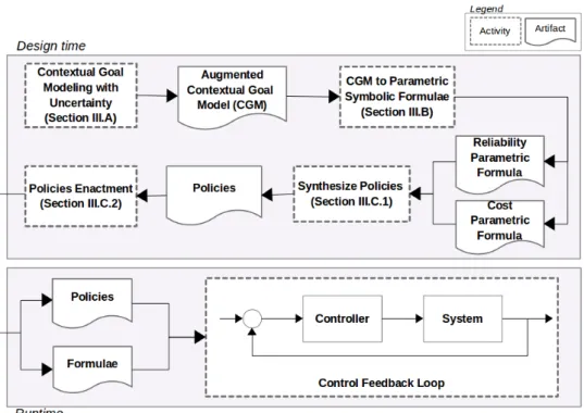
Furthermore, we follow the design-time process from Solano et al. [10] from contex-tual goal modeling to the parametric formula generate and contribute with an automatic runtime policy synthesis at runtime, see Figure 2.5. In this work, the contextual goal modeling extends GODA [9] with capabilities of taking uncertainties into account. In addition, the CGM to parametric symbolic formula process generates formal models, i.e. algebraic formulae, embedded with the representation of uncertainties for reliability and cost. The processes are further detailed in the next topics.
Figure 2.5: Goal-oriented design process for SAS
2.3.1
Contextual Goal Modeling
According to [11], a contextual goal model (CGM) is composed of: (i) actors such as humans or software that have goals and can decide autonomously on how to achieve these goals; (ii) goals as a useful abstraction to represent stakeholders’ needs and expectations, offering an intuitive way to elicit and analyze requirements; (iii) tasks as atomic parts that are responsible for the operationalization of a system goal, that is, an operational means to satisfy stakeholders’ needs; and (iv) contexts as partial states of the world that are relevant to a goal. A context is strongly related to goals since context changes may affect the goals of a stakeholder and the possible ways to satisfy the goals. Goals and tasks of a CGM can be refined through AND-decomposition or OR-decomposition, that is, a link that decomposes a goal/task into sub-goals/tasks, meaning that all or at least one, respectively, of the decomposed goals/tasks must be fulfilled/executed to satisfy its parent entity. The link between a goal and a task is called means-end, and indicates a means to fulfill a goal through the execution of a task.
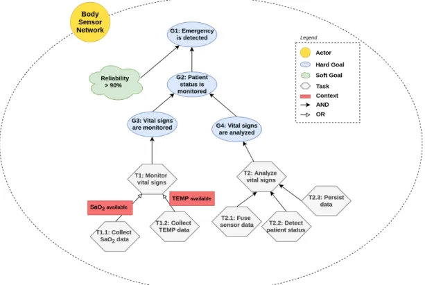
In the example of Figure 2.6, the Body Sensor Network, actor, and its main objective is elicited as the root goal "G1: Emergency is detected". To decompose the goal tree until the tasks that operationalize the root goal, one should ask herself what it needs to be done to satisfy the root goal and how. Then, G1 is decomposed into a soft goal (how) and a hard goal (what), as for the soft goal, it is stated that G1 must be achieved with at least 90% reliability, and for the hard goal that the patient should be monitored, "G2:
Figure 2.6: Contextual goal model example
Patient status is monitored". Next, G2 is decomposed into "G3: vital signs are monitored" and "G4: Vital signs are analyzed", through an AND decomposition since both must be realized. Both goals are decomposed into tasks, "T1: Monitor vital signs" and "T2: Analyze vital signs", respectively. Such tasks are decomposed, within the boundary of the Body Sensor Network actor, to finally reach executable tasks. T1 is decomposed into T1.1 and T1.2, supported by an OR decomposition, stating that to fulfill the vital signs monitoring, the system could collect SaO2 data or temperature data. T2 is decomposed
into "T2.1: Fuse sensor data", "T2.2: Detect patient status" and "T2.3: Persist data" within an AND decomposition. The operation of the Body Sensor Network is subject to two context conditions, both regarding the availability of the sensors needed to collect vital signs data.
2.3.2
CGM to Parametric Formulae Transformation
Parametric formulae are key enabler towards runtime analysis [9], since its computa-tion is constant. The produced formulae composes each tasks’ QoS attributes, regarding its operation, the contextual information associated and the means to satisfy the root goal. Therefore, the formulae can be used in the application behavior analysis since the parameters are constantly collected and updated during runtime.
The transformation technique is automatic stands for traversing the contextual goal tree and composing the nodes through arithmetic operations regarding the nodes and edges relations, in terms of decomposition, runtime behavior, weights, contexts, thus comprising an exogenous vertical transformation. In piStarGODA-MDP for example, the formulae is created over a process of building parametric MDPs, in respect to the execution behavior in Figure 2.7, in PRISM language for each leaf task node in the CGM and assembling them to represent the root goal fulfillment.
Figure 2.7: Software module execution behavior [9]
Furthermore, the tool relies on the root goal specification upon the probabilistic ex-istence property, which evaluates the probability of the system eventually reaching a state that satisfies a goal of interest. Finally, it uses the parametric model checking PARAM [25] to generate the parametric formulae in a bottom-up fashion (i.e. from leaf-tasks to root goal), see Figure 2.8. Since G3 has no specific feature, its reliability will be the same as its subtree “T1: monitor vital signs". Subtrees T1.1 and T1.2 have both an
AND-decomposition, thus the reliabilities of each subtrees are multiplied to obtain the reliabilities of each, T1.1 and T1.2. Finally, the leaf nodes have their reliability retrieved
by PARAM, in which rTi and f Ti represent the reliability and execution frequency of leaf
node i. Similarly, cost formulae are generated by the algorithm.
Chapter 3
Our Approach
3.1
Introduction
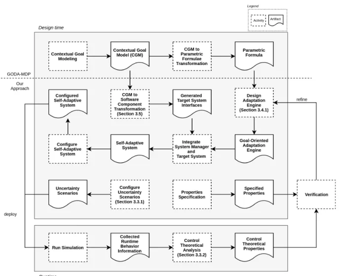
The present work provides an end-to-end conceptualization of an architecture for sup-porting adaptation engines verification and analysis. Moreover, it contributes seamlessly to the goal-oriented design process of trustworthy self-adaptive software systems. First, we introduce our view on the design process where we contribute to the goal-oriented SAS process from Solano et. al [10]. Then we present a vision of the concrete architecture that integrates the elements for a goal-oriented adaptation process in which the system is exercised with the injection of disturbance that lead into a control theoretical verification. The design process is represented by three parallel lines that merge into one that in a big picture ensembles a feedback loop, see Figure 3.1. The first line, withdraws the Contextual Goal Model (CGM) and transforms feasible tasks into components that compose the target system. The second, derives from the parametric formula which is used on the adaptation engine design. Both lines, merge into a single one which culminates into a self-adaptive system (SAS) through an integration process, which finally is configured by the system engineers and it is ready-to-go to runtime. The third line consists of setting uncertainty scenarios which will exercise the SAS in a runtime simulation in parallel to the desired properties specification for verification purposes. During runtime, information regarding the system behavior is collected and a control theoretical analysis is performed. This provides the system engineers with quantitative evidence on how the SAS behaves in the presence of uncertainty and may lead to refinements into the adaptation engine design, closing the feedback loop and contributing to trustworthy adaption engines design. Our architecture provides means for performing each of the aforementioned processes that contribute on the provision of concrete means for the adaptation engine verification process. It is composed of four major layers, two horizontal and two vertical. Wherein the
adap-Figure 3.1: The process view
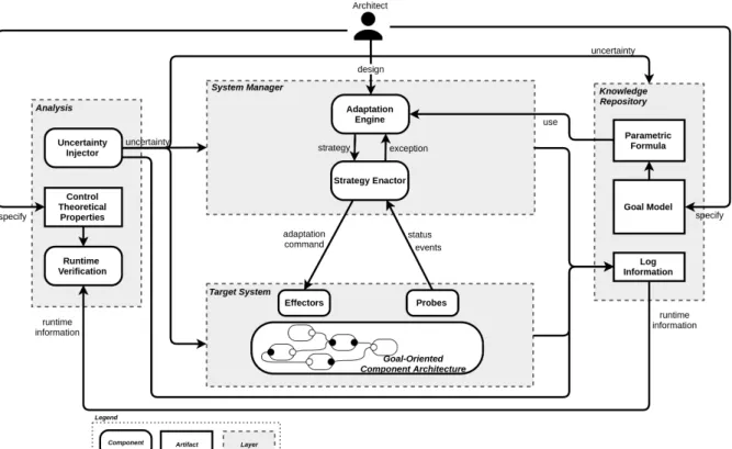
tations to be taken, the requirements in goal-model fashion and the runtime behavior information. The Analysis layer contains the components for exercising scenarios into during runtime and the verification of the system behavior. The System Manager layer is represented by the adaptation engine and strategy enactor components which guides the system to fulfill its adaptation goals. Finally, the Target System layer is composed by the system to be adapted and the components that monitors and effects on it. Figure 3.2 depicts the architecture where white round-shaped squares represent procedures and white sharp-shaped squares artifacts, arrows represent the direction of the data flow, and, as a result, dependency between components.
The next few sections furthers down into each layer of the architecture presenting conceptual aspects of the containing components and how they pervade the design process.
Figure 3.2: The architecture
3.2
Knowledge Repository
The knowledge repository is orthogonal to the other layers since it contains the mod-els necessary for the reasoning procedures at all levmod-els. As in this approach we advocate the importance of a goal-oriented design-process, the models suggested are goal mod-els, following from goal-oriented requirements engineering literature [12]. The knowledge repository content can be fed either at design-time through stakeholders (e.g. require-ment engineers, product owners, analysts) or at runtime through mechanisms that collect system information for requirements and models improvement.
The goal model is subject to input/output operations at any time, since the stake-holders and automatic inference mechanisms might guide the system towards new or updated goals. It is desired that the model updates are performed without any system outage because the components might rely on the goal model at runtime regarding the decision-making process. Then, the goal model must be ready for use in persistent storage or memory. Persistent storage approaches tend to be more resilient to faults while in-memory provides better performance, a hybrid approach might be eligible when trade-offs between the qualities are required.
Either way, the employed approach should be transparent to the goal model consumers and producers. Therefore, an interface must provide the high-level operations on the
model with guarantees that no inconsistent state is present and that all layers have access to the same model. Each layer requires distinct perspectives of the model (e.g. goal tree, symbolical formula), since the decision-making reasoning is subject to performance issues and lower layers usually tend to require faster response in comparison with upper layers. As a result, models automatic transformation is advised in order to guarantee consistency between the models used in different layers.
Following Solano et. al [10] we advocate for the employment of Contextual Goal Models (CGMs) and its respective derived formula for decision-making in our approach. Contextual information may hinder different system configurations which provides the means for adapting the system. Also, in their work, a set of uncertainties may be rep-resented on the parametric formula. This provides flexibility on the adaptation engine reasoning process with not much loss on computational effort. In addition, the trans-formation from CGM to parametric formula is fully automatic and complies with the necessary mechanisms for assuring consistency between models in the layer. For more information on the transformation process from contextual goal modeling to parametric formula please refer to the Section 2.3.2.
3.3
Analysis Layer
The analysis layer is orthogonal to all other layers. Even though it is not part of the deployed software artifact, it plays an important role by stressing an instance of the designed system for the provision of qualitative and quantitative arguments regarding the adaptation engine quality. It provides the system engineers with a mechanism for evaluat-ing how well the adaptation engine behaves in face of isolated or composed uncertainties before deploy. The current work, inspired by mRUBiS [19], presents two architectural components that are at the core of the analysis layer, the uncertainty injector and the runtime verification procedure. Finally, it suggests how the user may explore uncertainty injection in all levels of the architecture to gather evidences on the adaptation engine behavior correctness.
In the light of the control theoretical analysis method, the process can be divided in three distinct steps: configuration, execution and verification.
Configuration. Consists of setting up an execution scenario within the model or
application to be exercised. It includes the configuration of each architectural component, duration and the means by which the model or system will be exercised, i.e. the input signals. The first strictly depends on the architectural components domain specific task to be realized, the second can be either mathematically predicted or empirically defined
by observing the time necessary for convergence or divergence and the third depends on which uncertainty source should be exercised and the signal the best defines it.
Execution. The system or the model is stressed through cycles of uncertainty
injec-tion and the persistence of the variables of interest evoluinjec-tion in time. During this step, the configured injector mechanism acts upon the application by enforcing noise by alter-ing structural system elements, i.e. parameters, floodalter-ing buffers, swappalter-ing functions or resources.
Verification. Collecting the data gathered during runtime, processing it and
syn-thesizing information w.r.t the property(ies) and plotting the timeseries that define the system evolution in time. The timeseries goes under thorough information extraction and comparison in terms of control theoretical based metrics. Finally, the extracted metrics can be compared to the desired properties.
3.3.1
Uncertainty Injector
Deviation on the delivered service is usually perceived at runtime, when an error turns active mostly due to emergent uncertainties. Despite of that, the uncertainty source might have been placed at any time. The injector as a runtime architectural component is re-sponsible for simulating the emergence of uncertainties during the execution, which is not strict only to runtime related uncertainties. Therefore, this subsection discusses uncer-tainty injection in a broader scope. The unceruncer-tainty sources compliant with the current work are based on Weyns et al. [13] compiled from Hezavehi et al. [5] into six different classes of uncertainty comprising twenty-three sources either isolated or composed into more complex types.
Within the System Itself class of uncertainty, the model uncertainty sources (i.e.
sim-plifying assumptions, model drift, incompleteness) are inherent to the accuracy of
the model used in the adaptation reasoning process. Therefore, model uncertainty injec-tion requires that simpler, incoherent or incomplete system models override the models used in the adaptation reasoning process. However, models are not only domain spe-cific but may pursue unique spespe-cification rules, since modeling techniques are constantly improved. As a result, the injector should provide means for periodically injecting pre-set models into the System Manager layer, overriding the complete and concrete models loaded from the knowledge repository. In addition to the System Itself class, the
adapta-tion funcadapta-tions source of uncertainty might as well be affected by uncertainty injecadapta-tion
by the simulation of misbehaving probes and effectors. This could be either through noise in the propagated information or failures that prevent the information from reaching its destination. Uncertainty injection in the form of noise into the Logging Infrastructure can also hinder uncertainty for automatic learning.
The Goals class of uncertainty is subject to sources of uncertainty upcoming from the high level system goals, which are local to the Knowledge Repository. Therefore, the uncertainty injection is performed by read and write operations in the goal models stored in the Knowledge Repository. However, the focus of the uncertainties to be injected are taken prior to the simulation, for design-time sources of uncertainty (i.e. requirements
elicitation, specification of goals), and during the execution, for runtime sources of
uncertainty (future goal changes). The design-time sources are related to the accuracy with which the system was modeled and requires that pre-set faulty goal models be provided in the configuration phase. The runtime sources encompasses changes in the goals which can be realized by noise injection in the goals parameters at runtime.
Additionally, the Context class of uncertainty is strict to runtime. Uncertainty in-jection for this class are realized within the target system. Such system interacts with the environment and might have distinct modes of operation depending on the context it is emerged in. Then, noise can be injected in the variables representing contextual data inside each component in the target system for the execution context source. Also, applications with sensors for perceiving the context are subject to noise in
sens-ing, due to accuracy, interference with other elements, and so on. The injection is thus
straightforward.
It is notable that Human Interaction class of uncertainty is out of the scope of this work. It is domain specific and the variety of options for human interactions in the goal-oriented design-process is wide enough and prone to innumerous possibilities.
3.3.2
Runtime Verification
The runtime verification is responsible for performing the tasks from raw data col-lection, processing and transformation into meaningful information to finally extracting relevant properties. In this work, the verification step is performed on system properties that evolve in time, a timeseries. First, the data collection is realized on the informa-tion persisted by the Logging Infrastructure into logs. Second, the procedure performs a processing and transformation of actuation signals, input signals and the system status into a timeseries response. Third, the properties extraction are placed in respect to the aforementioned control-theoretical metrics 2.1.
In this work, several components contribute to each other for the fulfillment of a main application goal represented by the concrete goal model tasks and decompositions. Then, the processing and transformation step should compose the information persisted for each of the components into a single overall behavior of the system, as in many cases the properties to be guaranteed are in respect to the general system behavior. The parametric formula derived from the CGM and stored in the Knowledge Respository can be employed
for verification purposes. As it provides enough information for being used for control theoretical verification even in face of uncertainties. All in all, it supports contextual information modeling, system properties representation and is prone to uncertainty.
In Figure 3.3, a typical response to a perturbation in the system is illustrated.
Figure 3.3: System behavior and metrics
The figure represents the outcome of the processing and transformation phase, which paves the way to the properties extraction step, further discussed in the next subtopics. Given that the outcome of the processing phase is an array of size N containing the values that represent the system response at each instant (T S).
Stability
A system is said to be stable when it reaches its state of steadiness. In Control Theory, the steady-state is defined by the interval in which the response curve stays inside the acceptable stability margin from the convergence point (usually 2% or 5%). In this work, the convergence point is calculated by the simple average of the last quarter of the timeseries values, Equation 3.1.
CP = N P n=3N4 T S[n] N 4 (3.1)
The evaluation that defines whether the response reached the steady state or not consists of querying if the last value (T S[N ]) is within the interval determined by the stability margin (−SM < T S[N ] < +SM ).
Settling Time
The settling time is time required for the response curve to reach stability. Marked in Figure 3.3 by the crossing from the vertical dashed line with the lowermost dashed stability margin line. From the settling time on, it is guaranteed that the response curve stays inside the stability margin.
Algorithm 1 Calculate Settling Time
1: procedure CalculateST
2: ST ← 0
3: for each sample in T S do
4: if −SM < sample < +SM then 5: if ST is 0 then 6: ST ← sample instant 7: else 8: ST ← 0 return ST
The Algorithm 1 returns the first sample instant that is inside the interval (−SM <
sample < +SM ) until a sample is out of the interval or the array is over. When the
response curve is not stable, the algorithm returns 0.
Overshoot
The overshoot, or maximum (percent) overshoot, indicates the maximum peak value of the response curve measured from the convergence point. The Equation 3.2 illustrates the mathematical model used for calculating the overshoot.
OS = T S[tp] − CP
CP · 100% (3.2)
Where the tp is the sample related to the highest peak on the response which can be
extracted with a maximum function iterating over the T S array.
Steady-State Error
The steady-state error is a measurement of how far from the precise setpoint value has the system response reached. It is calculated by the relative distance between the
convergence point and the setpoint, defined by the system stakeholders, see Equation 3.3. Be setpoint the value determined as the desired final state for the response curve,
SSE = | CP − setpoint |
setpoint · 100% (3.3)
3.4
System Manager Layer
The System Manager layer contains the architectural components for adapting the target system. It constantly monitors the system status and triggered events. Then, based on a model and the system requirements, an analysis is performed towards deciding whether it is needed to adapt the system. Furthermore, a planning routine decides a strategy that might lead the system towards reaching its goals. At the end of a cycle, the strategy is executed. This structure might be repeated on as many sublayers inside the system manager layer as the engineers find useful. Distinct layers can be applied by means of performing hierarchical adaptation in which lower layers propagate exceptions upwards when they cannot find a strategy that fulfills the current goal, due to contextual constraints. Thus, upper layers which perform higher level reasoning processes may find a sufficient or the best strategy for the situation, propagating it downwards.
We present a minimal two-layered architecture containing an adaptation engine for higher level reasoning and a enactor for lower level strategy enforcement. However it is not our intention to limit the number of layers, since our goal is of verifying different proposals of adaptation engines. The two following subsections dive into major theoretical aspects of both architectural components.
3.4.1
Adaptation Engine
Responsible for higher level reasoning, the adaptation engine architectural component must be capable of performing computationally expensive decision-making algorithms. Search in adaptation space is particularly difficult to solve as the size of the adaptation space grows in exponential order since it is prone to the combination of possible solutions. Specially when it accounts to not only the execution or not or each target system compo-nent, but the interaction of components to satisfy the goal. Which increases even more when more than one parameters for each components are taken also considered.
Despite the difficulty, approaches propose goal-oriented requirements formalization by enabling uncertainty to be modeled in goal-oriented notation [7, 10, 26, 27]. Reasoning upon these models is still not free from state explosion, but constraints can be elicited to build heuristics which lead to feasible solutions. The parametric formula employed in this work is used for both analyzing the current status of the overall system property
of interest and for calculating through a search-based solution, the combination of local (goal, condition, actions) that would lead the system into reaching its objective.
The Figure 3.4 details the feedback loop corresponding to high-level processes em-ployed the strategy synthesis. Where a Pref is the system overall property to be
con-stantly monitored and guaranteed during runtime, it is provided by an external agent. The error is composed by the difference of where the system currently is (Pcurr) and where
it wants to get (Pref). The need adaptation? block, queries if the error is bigger than
the expected. And the evaluate actions loop through the parametric formula, searching for the combination of terms that would lead the system into reaching Pref. When the
combination is found it is propagated to the strategy enactor in the form of strategy.
Figure 3.4: Detailed vision of the adaptation engine
The reasoning process follows the Algorithm 2 written in pseudo-code. Where Ps is
the set of properties monitored from the system, labeled as “system information” upon the thick line in Figure 3.4. Line 4 calculated the error based on the desired Pref and
the current Pcurr. Line 5 corresponds to the analysis on whether the adaptation needs
to be performed, querying if the error is within the acceptable stability margins. And from line 6 - 21, the evaluate action block is performed by a search with heuristics within the possible adaptation space. Finally, line 22 corresponds to the strategy selection and propagation to the Strategy Enactor.
The evaluate action block from line 6 to 21 uses incremental gains on the error for reaching the desired reference value, other strategies could be employed for reaching the desired value. The algorithm is run periodically in a preset actuation frequency and collects a configurable quantity of status messages from the target system in order to calculate the current system property. It performs a search in the solution space (R), that starts in the value determined by a percentage of the current property value, determined by the offset. For example, if the current system property value is 0.80, the offset is 20% and the error is bigger than 0, then the search starts at 0.54 for each and every component. In the case of the error being smaller than 0, the offset is applied as an increment to the current property value. Also, the Kp determines the granularity of each search step since. It is noteworthy that smaller Kps might lead the into more precise
Algorithm 2 Adaptation Engine Pseudo-Code
1: procedure AdaptationEngine
2: Ps← monitor system
3: pcurr ← apply Ps to parametric formula
4: error ← pref − pcurr
5: if −stabilityMargin < error < stabilityMargin then return true
6: for each pi in Ps do
7: Ps ← ResetToStartingPoint(offset)
8: pnew← apply Psto parametric formula
9: if error > 0 then
10: pi ← pi+ Kp · error until pnew > pref
11: where pnew ← apply Ps to parametric formula
12: for each Rj in Ps− pi do
13: rj ← rj+ Kp · error until pnew > pref
14: where pnew← apply Ps to parametric formula
15: else
16: pi ← pi− Kp · error until pnew < pref
17: where pnew ← apply Ps to parametric formula
18: for each Rj in Ps− pi do
19: rj ← rj− Kp · error until pnew < pref
20: where pnew← apply Ps to parametric formula
21: Strategies ← Strategies + Ps
22: Send a strategy from Strategies that satisfy the stabilityMargin
solutions and might even be necessary for reaching a solution. However, the smaller it is, the bigger is the search space, which can invalidate the algorithm in terms of scalability. Finally, the pref determines the setpoint to be achieved by the search. Thus, the algorithm
can be configured in terms of these parameters.
3.4.2
Strategy Enactor
The enactment level architectural components are responsible for enforcing one or more active strategies at the target system. The strategies are synthesized in the adaptation engine and must be read, interpreted and enforced by the strategy enactor. It is the strategy enactor’s responsibility to evaluate whether the active strategy truly leads the system into the desired behavior, thus monitoring the system events and status must be constantly performed. If the active strategy does not lead the system into fulfilling the system goals or no strategy among the present ones could lead the system towards its goals, exceptions might be thrown to the upper layer with statements or constraints that supports the adaptation engine strategy synthesis.
As illustrated by Figure 3.5 the active strategy is composed by Goal, a Condition and an Action. The goal placeholder determines the property reference to which the compo-nent should converge to. The condition is used to determine whether the current error satisfies the requirements. And the action drives the system into reaching the desired goal. The strategy enactor interfaces directly with the target system by sending adapta-tion commands and receiving system informaadapta-tion through status and event messages.
Figure 3.5: Detailed vision of the strategy enactor
3.5
Mapping from Goal-Model to Components
According to Szyperski et al. [28], "a software component is a unit of composition with
contractually specified interface and explicit context dependencies only". From such
defini-tion, we derive that the most important aspect of components is the separation between implementation and interface that enable seamless integration with other components. In the goal model, the means-end tasks suffice the requirement of being an independent entity that completely fulfills a higher level goal at a concrete level. Then, composed with others, such tasks contribute to the fulfillment of the main goal of the application.
Without loss of generality, in this work, we propose a mapping from means-end tasks to components. In this case, we assume that each component in the architecture encapsulates the tasks that decompose the respective means-end task. Also, this mapping does not limit the software design decisions in terms of what is a component and how the means-end tasks decomposition compose with each other. They might be designed as functions, methods, classes, modules or whatever software building block sound reasonable to the system engineers. Despite of that, it is required that a mathematical model relating the composed building blocks to the property to be adapted is provided to single means-end task. Which can then be plugged into the parametric formula.
It is noteworthy that the mapping suggested in this work is no more than a contract between the requirements engineering process and the implementation of the system. The components correct implementation and binding is left to the system engineers and is a manual process.
Figure 3.6: Goal to component mapping example
In the illustrated example of Figure 3.6, we demonstrate a mapping between means-end tasks, ’T1: Collect pulse oximeter’, into the class G3_T 1 that implements the methods defined by the interface class Component. The class G3_T 1 contains available and data as attributes, where the available is a boolean value that evaluates in correspondence to the contextual information of the task and the data contains the information to be exchanged through the leaf-tasks implemented as methods collect, process and transfer. A pseudo-code containing the implementation of the Component inherited methods is represented in Algorithm 3. Algorithm 3 G3_T1 1: procedure SetUp 2: available ← T rue 3: procedure TearDown 4: available ← F alse 5: procedure Run
6: if available is T rue then
7: isCollected ← collect(data) 8: isProcessed ← process(data) 9: isTransferred ← transfer(data) 10: else
11: skip
Whereas the implementation of collect, process and transfer behaviors are in charge of the system engineer. In the case of OR decomposition instead of only ANDs, the return statement would change to suffice the first-order logic derived which state whether a run cycle was successfully performed or resulted in a failure.
3.6
Target System Layer
The target system layer contains the system that is ought to deliver the service that fulfills the functional requirements and mechanisms for monitoring and adaptation. Such layer is subdivided into three architectural components: probes, effectors and system.
The probes are meant for system’s data collection and pre-processing data gathered via instrumentation internally to the component or upon the communication infrastructure. Either way, the probes shall continuously evaluate emergent changes into the system state that are relevant to the property to be adapted. The information that evidences the changes should be collected and propagated to decision-making structures, e.g. the
system manager layer.
The effectors, in turn, are responsible for acting on the target system. The actuation may refer to either behavioral or reconfiguration aspects of the system. Each system component must be instrumented with actuation mechanisms that enable change during runtime. Behavioral changes are domain dependent and subject to the provided services from each component. The reconfiguration can be either domain dependent or indepen-dent. While the dependent is prone to the system parameters, the independent deals with components insertion, removal and binding.
Finally, the system to be adapted’s architecture should be flexible, though following some basic principles to ensure runtime adaptability is advised. In this work, it is required that each self-sufficient task should be mapped into independent components that upon execution satisfies a well delimited goal. In addition, each component should be mapped into the parametric formula elements. The goals to components mapping provides the necessary structural rules for enacting adaptable components.
3.7
Logging Infrastructure
The logging infrastructure is motivated by the need of monitoring and evaluating the system behavior in face of runtime changes, which is directly related to how well the adap-tation engine fits its purposes. Therefore, a transparent logging layer constantly monitors the messages that travel through the communication channels between the System
This work assumes that the manager and target system layers share information through message exchange. Logging can be accomplished in two ways: centralized logging or distributed logging with information aggregation. The centralized solution is simpler than the distributed. However, it demands additional effort for guaranteeing event or-dering and for avoiding the bottleneck on systems with many nodes. On the other hand, there is a necessity of time synchronization between the nodes that participate on the logging task in a distributed systems domain. Even though global clock synchroniza-tion is a well-established problem in distributed system community, its implementasynchroniza-tion is harsh and depending on the adopted solution, a communication network overload can be observed. Also, it is required that a log aggregator is deployed to correctly merge the logs, which should not be a problem for globally ordered events.
A fundamental information to be logged for each message that passes by the logging infrastructure is the message’s emitting source. Even though the goals to components mapping guarantees that each means-end task are implemented as a singular and self-sufficient component, the logging infrastructure must make sure that this information is associated to the event and status messages propagated upwards by the probe. So, that the Analyzer and the System manager can correctly map each component property to its respective term in the formula.
Chapter 4
Case Study and Evaluation
4.1
Body Sensor Network a Case Study on ROS
To discuss our proposed methodology, we use the exemplar implementation1 of a Body
Sensor Network (BSN) [29, 30]. The main objective of the BSN is to keep track of a pa-tient’s health status, continuously classifying it into low, moderate, or high risk and, in case of any anomaly, to send an emergency signal to authorities on the subject. The structure of the BSN is as follows: a few wireless sensors are connected to a person to monitor her vital signs, namely, a pulse oximeter (SaO2) for blood oxidation, an
elec-trocardiograph (ECG) for heart rate, a thermometer (TEMP) for temperature and an arterial blood pressure monitor (ABP) for systolic and diastolic blood pressure measure-ment. Additionally, there may be a central node responsible for analyzing the collected data, fusing it, identifying the patient’s health status and finally emitting an emergency message if necessary.
A more precise description of the BSN is detailed by its requirements that are repre-sented by a goal-model, as depicted in Figure 4.1. The goal model goes through a vertical and exogenous transformation for algebraic formula derivation [10] and is mapped into the target system components as suggested in this work. Modeling a SAS requires to take into consideration not only the requirements and means to achieve them, but also the contextual information that may be related to the system’s operation. For this purpose, we use a Contextual Goal Model (CGM) since it allows us to specify in a simple structure the stakeholders and high-level requirements, the ways to meet such requirements, and the environmental factors that can affect the quality and behavior of a system. According to Figure 4.1, the Body Sensor Network, actor, and its main objective is elicited as the root goal "G1: Emergency is detected". Then, G1 is decomposed into a soft goal and a hard 1The case study is avaliable at https://github.com/rdinizcal/master_thesis_eval along with all
Figure 4.1: Body Sensor Network Goal Model
goal, as for the soft goal, it is stated that G1 must be achieved with 95% ± 2% reliability, and for the hard goal that the patient should be monitored, "G2: Patient status is moni-tored". Next, G2 is decomposed into "G3: Vital signs are collected" and "G4: Vital signs are analyzed", through an AND decomposition since both must be realized. The former is decomposed on 4 goals with an ’OR’ decomposition indicating that at least one should be realized to fulfill its objective, for the collection of specific sensor’s data, which are re-alized by the means-end tasks T1.1, T1.2, T1.3 and T1.4: collect SaO2 data, ECG data,
temperature data or blood pressure data. The latter is decomposed on the means-end task "T1: Analyze vital signs" which states that the BSN should analyze the vital signs to identify and detect an emergency. Finally, each means-end task is still decomposed on the leaf-tasks, that in conjunction operationalize the means-end task. The operation of the Body Sensor Network is subject to four context conditions: SaO2, ECG, T EM P and
ABP . Each of them refers to the availability of their respective sensors needed to collect
vital signs data.
The BSN self-adaptive software implementation follows the conceptual architecture presented in the approach and make use of the Robot Operating System (ROS) middle-ware for message exchange 4.2. Where the ROS Master is the name server for registering, deregistering and lookup ROS nodes and communication topics. The communication top-ics are used for peer-peer communication with publish/subscribe protocol. The common
![Figure 2.2: The MORPH reference architecture [20]](https://thumb-eu.123doks.com/thumbv2/123dok_br/18413834.894704/17.892.183.709.651.1067/figure-the-morph-reference-architecture.webp)
![Table 2.1: Behavioral metrics adapted from [18]](https://thumb-eu.123doks.com/thumbv2/123dok_br/18413834.894704/20.892.111.777.196.503/table-behavioral-metrics-adapted-from.webp)
![Table 2.2: Transformation definitions [24]](https://thumb-eu.123doks.com/thumbv2/123dok_br/18413834.894704/22.892.104.789.125.529/table-transformation-definitions.webp)