Crystalline Silicon PV Module under Effect of Shading
Simulation of the Hot-Spot Condition
R.S. Anjos2, R. Melício1,3, V.M.F. Mendes1,2, H.M.I. Pousinho1,2
1Universidade de Évora, Escola de Ciências e Tecnologia ,Departamento de Física, Portugal
2Instituto Superior de Engenharia de Lisboa ,Portugal; [email protected] 3Universidade de Lisboa ,Instituto Superior Técnico, IDMEC, Portugal
Abstract. This paper centers on the silicon crystalline PV module technology subjected to operation conditions with some cells partially or fully shaded. A shaded cell under hot-spot condition operating at reverse bias are dissipating power instead of delivering power. A thermal model allows analyzing the temperature increase of the shaded cells of the module under hot-spot condition with or without protection by a bypass diode. A comparison of the simulation results for a crystalline PV module without shading and with partial or full shading is presented.
Keywords: Hot-spot, PV systems, shading effect, breakdown voltage, modelling.
1 Introduction
The demand for energy, the scarcity of nonrenewable fuels and the need for CO2 emissions decrease have resulted in a consciousness of the significance of energy efficiency and energy savings [1,2] and DSM software and Smart Grid architecture have been developed in order to endure consumers on energy use. Also, renewable energy sources coming from solar and wind energy sources are attractive to go into exploitation, considering large scale and mini or micro scale conversion systems [1,3]. A photovoltaic system (PVS) converts solar energy into electric energy. The main device of a PVS is a cell. Cells may be assembled to form modules or arrays. A module is composed by cluster of cells linked in series. An array can be a module or a set of modules linked in parallel, series, total cross tied or bridge-linked to form large PVS. These PVSs may have or not a tracking system in order to achieve higher energy conversion values during sunny days due to the diverse positions to accumulate the sun´s irradiation [4]. The array performance depends on the solar irradiation, operating conditions, array configuration, environmental parameters as temperature and wind speed, and shading. The shading on arrays occurs due to the dust, bird droppings, leaves, snow or shadowing caused by near buildings, near trees or a passing cloud. The shading can be partial or full with respect to a PV module [5]. The existence of shaded cells in a module causes a mismatch on the equilibrium of photo-generation of electron-hole pairs of the cells. Under this mismatch, a non-shaded cell of the module operates at a generation of carriers higher than those of the shaded ones [5]. Consequently, the shaded cells are into reverse bias [5]. The hot-spot occurs after a cell, or cluster of cells in a PV module, operates at reverse bias, dissipating power and operating at abnormally high temperatures. Cells exposed to
higher temperatures will degrade at a higher rate than others. If a cell is shaded and operation at high temperatures occurs for a long time, then irreparable damage is due to happen to the solar cell. If a bypass diode is used, a cell in reverse bias renders useless the rest of the cells under the bypass diode [6]. The hot-spot occurrence is particularly frequent and always happens when a shadow covers the module, thus reducing the photo-generated current [7,8]. In order to protect shaded cells from breakdown voltage (BV), bypass diodes linked in antiparallel with the cell or module is applied. In the 1990s authors contributed to improve the PVS module design and to determine the maximum solar cells number per bypass diode in order to avoid the hot-spots condition [9,10]. Based on these knowledges, according to IEC 61215 a hot-spot endurance test became part of the type approval for crystalline silicon modules [8].
The diodes bypass limit the reverse voltage that can be applied to a cell, thus avoiding it from reaching the BV when the cell is shaded [6]. Due to impurities and defects inside the silicon, some cells may display a great reverse current even before reaching the BV. This impurities and defects inside the silicon are commonly modeled by inserting a shunt resistance, whose value depends on the distribution of defects/impurities and concentration inside the cell [6]. If the shunt resistance is low enough the hot-spot condition can occur even before that the PV cell enters the BV even if bypass diodes are used [6]. In this case, due to the hot-spot heating, the PV cell can reach a temperature high enough to cause permanent damage, although this takes longer to occur than when the PV cells operates in breakdown voltage [6].
This paper is considered with the exposition to shading of a silicon crystalline PV module and as a consequence subjected to condition of hot-spot. A thermal model is used in order to allow estimating the temperature of the area subjected to the condition of hot-spot. The paper is systematized as follows. Section II presents the relationship to smart systems. Section III presents the modeling of the PVS module forward biased, using the five parameters model, i.e., the single-diode, shunt and series resistances circuit; the model of the PV module reverse biased; and the thermal model which allows estimating the hot-spot temperature. Section IV presents the case studies. In the first case, the I-V characteristic curves are simulated considering the reverse bias of the PV module: simulation results for a silicon crystalline PV module technology without shading are compared with the module partially shaded or fully shaded; without or with bypass diode. In the second case, a thermal model allows analyzing the temperature increase of the shaded cells of the module subjected to condition of hot-spot without or with a bypass diode. Finally, concluding remarks are given in Section V.
2 Relationship to Smart Systems
Technological Innovation has entered into the age of smart systems and smart grids, when machines implement human functions of analyzing real data and making decisions [11]. A Smart system is an embedded systems architecture which embodies advanced automation systems to provide control and monitoring over the something's functions, for example a PVS. Hence, the advances in science and technology allow the opportunity to bridge physical components and cyber space, leading to Cyber-Physical Systems [12,13]. The coordination and interaction of smart systems of PVSs require handling number of challenges to increase the reliability and the service life
time of the PV modules. The performance of a PV modules depends on the operating conditions, i.e., depends not only on solar irradiation and temperature, but also on the array configuration and shading effects. The hot-spot on a PV cell produces degradation or a permanent damage in the shaded cells, with a consequent reduction of the provided power [14].
Statistics show degradation rates of the nominal power for thin-film and silicon PVS modules of 0.8%/year [15]. Hence, to raise the service life and the reliability of PVS modules one has to recognize the challenges involved. Successfully integrating PV power into the existing electric grid is a complex challenge that relies on distributed, interconnected smart systems, which are proliferating within the engineering industry [12].
3 Modeling
The circuit for the PVS entails in a current controlled generator, a single-diode, a shunt and series resistances. Thus for the forward bias module the I-V characteristic is formulated [5] given by:
p S mV IR V S R IR V e I I I T S ) 1 ( 0 (1)
where the output module current is I, the photo-generated current is IS, the reverse
bias saturation diode current is I0, the output voltage is V, the shunt and the series
resistances are respectively Rp and RS, the ideality factor is m, the thermal voltage of
the p-n junction is VT.
This circuit for the reverse bias module is shown in Fig. 1.
Where in Fig. 1 the current through diode D is ID, described by the Shockley diode
equation, the reverse breakdown current which is a portion of Ip dissipated in Rp when
the module is reverse biased is Ibd [5,6].
For the reverse bias module, the Ibd [11] is given by: b bd S p S bd V IR V a R IR V I (1 ) (2) where the portion of the linear current involved in avalanche breakdown is a . For the reverse bias module the I-V characteristic is formulated by an implicitly function [16] given by:
] ) 1 ( [1 ) 1 ( 0 b bd S p S mV IR V S V IR V a R IR V e I I I T S (3)
Rs Is Rp Ip I G -V + -D ID . Ibd
Fig. 1. Circuit for the reverse bias module.
The thermal model allows estimating the temperature THS of the module’s area AHS
under hot-spot condition [5,6]. The time instant t at which the PV module goes into shading condition and reverse biased is denoted by tHS. Considering the PV module
staying into shading condition from tHS until at time t ≥ tHS, the temperature THS (t) is
incremented relatively to the ambient one, Tamb. The expression for computing THS (t)
[6] is given by: ii i T t THS() amb (4) where i and ii [6] are respectively given by:
] ) 1 ( [ ) ( TH TH HS C R t t THAG e R i (5) ] 1 [ ) ( HS TH HS TH HS C R t t HS TH dissR e P ii (6)
where the whole PV module area is A, the solar irradiance is G, the relative gap in the irradiation between the non-shaded modules and the shaded module linked in series is γ, the dissipated power on the Rp resistance of the shaded module is Pdiss, the
thermal capacitance and thermal resistance of the module with area AHS under
hot-spot condition are CTH-HS and RTH-HS, respectively, the thermal capacitance and
thermal resistance of the remaining module area are CTH and RTH. In the thermal
model, the parameters RTH-HS, CTH-HS are constants and depend of the materials which
composing the upper layers of the module cells [6]. Considered hot-spot condition on the two cells of the PV module with 36 cells is shown in Fig. 2.
In Fig. 2, Acell is the area of each cell of the module and AHS is the area of the
module under hot-spot condition. The range of values of AHS for the simulation is
taken from [6], where is said to be set experimentally in the range between 5% and 10% of Acell.
Fig. 2. Two cells shaded PV module under hot-spot condition [5].
4 Simulation Results
The models for the PV module forward biased, for the PV module reverse biased and for the thermal model that allows assessing the temperature of the area under hot-spot condition are implemented in Matlab/Simulink.
The module has 36 cells linked in series, the shaded area AHS is equal to the area of
two cells, i.e., taking approximately 5.6% of the area A associated with the capture of energy.
The data of the manufacture for the crystalline silicon PV module Isofotón I-53 at STC [17] is displayed in Table 1.
Table 1. Isofotón I-53 solar module data
Technology Vm* I*m Voc*
* sc
I Crystalline 17.4 V 3.05 A 21.65 V 3.27 A
The forward breakover voltage considered for silicon diode is 0.7 V. The equivalent circuit for the reverse bias module shown in Fig. 1 has the values for the RP
and RS given in [16].
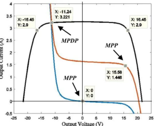
First Case Study. The simulation results for a silicon crystalline PV module technology without shading are compared with the module partially shaded (MPS) or fully shaded (MFS) in order to study the current and voltage when the module is reverse biased.
Considering the MPS or MFS linked in series with one non-shaded module, if the shaded module is a MPS his irradiance is 500 W/m2 and if shaded module is MFS his irradiance is 0 W/m2. When the shaded PV module is reverse biased we assume Vbd = -10 V, a = 1.93 and b = 1.10 in (3). Considered that the module is without
respective symmetric curve (also in black but in the second quadrant), the I-V curves of the MPS (orange) or MFS (blue) are shown in Fig. 3.
Fig. 3. No bypass protection. I-V curves (black), MPS (orange), MFS (blue).
Fig. 3 reveals that at the maximum power dissipation point (MPDP) the MPS and the MFS is reverse biased with a same voltage value of -11.24 V and a current value of 3.22 A. The maximum power point (MPP) when the module is partially shaded is at a voltage value of 15.58 V and a current value of 1.45 A.
Considered that the module is with bypass diode: the I-V reference curve of the non-shaded module (black) and respective symmetric curve (also in black but in the second quadrant), the I-V curves of the MPS (orange) or MFS (blue) are shown in Fig. 4.
Fig. 3. Bypass protection. I-V curves (black), MPS (orange), MFS (blue).
Fig. 4 reveals that at MPDP the shaded module is reverse biased with the value of voltage of -0.70 V and the value of the current of about 3.38 A.
A comparison of Fig. 3 and Fig. 4 allows observing the effect of the bypass protection. The maximum power dissipated in the shaded module without bypass
MPP MPDP MPP MPP MPDP MPP
diode is 36.20 W at MPDP while for the shaded module with bypass diode is 2.28 W at MPDP. For the two case studies the maximum power point (MPP) when the module is partially shaded is at a voltage value of 15.58 V and a current value of 1.45 A, while when the module is fully shaded the voltage value is 0.00 V and a current value is 0.00 A. Hence, the bypass diode does not affect the module at MPP. in [17].
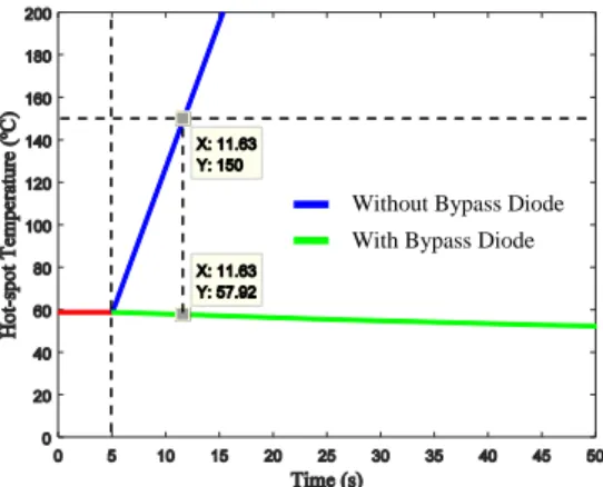
Second Case Study. The simulation results for a silicon crystalline PV module technology without shading are compared with the module partially shaded or fully shaded in order to evaluate the evolution of the module temperature under hot-spot condition. The value of Tamb considered is 25ºC and the time instant tHS considered is
5 s. Consider the MPS operating at MPDP the curves of the temperature THS for the
area under hot-spot condition in function of the time: without bypass diode (blue) and with bypass diode (green) are shown in Fig. 5.
Fig. 5. MPS, temperature on the area of hot-spot condition.
The PV module has a THS of approximately 60ºC for a lower than tHS = 5 s. Fig. 5
reveals that the MPS without bypass diode reaches the critical temperature of 150ºC [6] at time of 11.63 s, i.e., 6.63 s after getting shaded and reverse biased, while with bypass diode decreases temperature 57.92ºC in same time. The curves of the temperature for the MFS in function of the time reveals that the MFS without bypass diode reaches the critical temperature of 150ºC [6] at time of 11.71 s, i.e., 6.71 s after getting shaded and reverse biased, while with bypass diode reaches the temperature of 56.79ºC in same time. Thus the MPS reaches the temperature of 150ºC faster than MFS not depending on the usage of bypass diode.
5 Conclusions
An addressing of a model for PV module under hot-spot condition is study in what regards the model simulation. The addressing allows concluding that when a module operates at reverse bias due to the non-uniform cells illumination, the module is exposed to a quantified temperature increase and substantial power loss. Also, allows quantifying the advantage of using the diode for bypass protection in what regards performance of the module.
Without Bypass Diode With Bypass Diode
Acknowledgment. This paper was in part supported by Portuguese Funds, Foundation for Science and Technology, UID-EMS-50022-2013, LAETA project 2015/2020.
References
1 Fialho, L., Melício, R., Mendes, V.M.F., Estanqeiro A., Collares-Pereira, M.: PV systems linked to the grid: parameter identification with a heuristic procedure. Sustainable Energy Technologies and Assessments, 10, 29–39 (2015)
2 Saraiva, S., Melício, R., Matias, J.C.O., Cabrita, C.M.P., Catalão, J.P.S.: Simulation and experimental results for a photovoltaic system formed by monocrystalline solar modules. In: Technological Innovation for Value Creation, Springer, 372, 329–336 (2012)
3 Fialho, L., Melício, R., Mendes, V.M.F., Estanqeiro, A.: Simulation of a-Si PV system grid connected by boost and inverter. International Journal of Renewable Energy Research, 5(2), 443–451 (2015)
4 Fialho, L., Melício, R., Mendes, V.M.F., Viana, S., Rodrigues, C., Estanqeiro A.: A simulation of integrated photovoltaic conversion into electric grid. Solar Energy, 110, 578–594 (2015)
5 Anjos, R.S., Melício, R., Mendes, V.M.F.: Simulation of the effect of shading on monocrystalline solar module technology under hot spot condition. In: Conference on Electronics, Telecommunications and Computers, 1–2, Lisbon, Portugal (2016)
6 Giaffreda, D., Omaña, M., Rossi, D., Metra, C.: Model for thermal behavior of shaded photovoltaic cells under hot-spot condition. In: Int. Symposium on Defect and Fault Tolerance in VLSI and Nanotechnology Systems, 252–258, Vancouver, Canada (2011) 7 Daliento, S., Di Napoli, F., Guerriero, P., d`Alessandro V.: A modified bypass circuit for
improved hot spot reliability of solar panels subject to partial shading. Solar Energy, 134, 211–2181 (2016)
8 IEC Standard 61215: Crystalline silicon terrestrial photovoltaic (PV) modules-design qualification and type approval. International Electrotechnical Commission (1995)
9 Arnett, J.C., González, C.C.: Photovoltaic module hot-spot durability design and test methods. In: 15th Photovoltaic Specialists Conference, 1099–1105, Kissimmee, USA (1981) 10 Shepard, Jr.N.F., Sugimura, R.S.: The integration of bypass diodes with terrestrial photovoltaic modules and arrays. In: 17th Photovoltaic Specialists Conference, 676–681, Orlando, USA (1984)
11 Arsan, T.: Smart systems: from design to implementation of embedded smart systems. In: 13th International Symposium on Smart MicroGrids for Sustainable Energy Sources enabled by Photonics and IoT Sensors, 59–64, Nicosia, Cyprus (2016)
12 Viveiros, C., Melício, R., Igreja, J.M., Mendes, V.M.F.: Control and supervision of wind energy conversion systems. In: Technological Innovation for Cyber-Physical Systems, 353–368, Springer (2016)
13 Fialho, L., Melício, R., Mendes, V.M.F., Collares-Pereira, M.: Simulation of a-Si PV system linked to the grid by DC boost and three-level inverter under cloud scope. In: Technological Innovation for Cloud-based Engineering Systems, 423–430, Springer (2015)
14 Rossi, D., Omaña, M., Giaffreda, D., Metra, C.: Modeling and detection of hotspot in shaded photovoltaic cells. IEEE Transactions on Very Large Scale Integration (VLSI) Systems, 23(6), 1031–1039 (2015)
15 Jordan, D.C., Kurtz, S.R.: Photovoltaic degradation rates-an analytical review. Progress in Photovoltaics: Research and Applications, 21, 12–29 (2013)
16 Ramaprabha, R., Mathur, B., Santhosh, K., Sathyanarayanan, S.: Matlab based modelling of SPVA characterization under reverse bias condition. In: 3rd International Conference on Emerging Trends in Engineering and Technology, 334–339, Goa, India (2014)
17 Fialho, L., Melício, R., Mendes, V.M.F.: PV system modeling by five parameters and in situ test. In: International Symposium on Power Electronics, Electrical Drives and Motion, 573–578, Ischia, Italy (2014)

![Fig. 2. Two cells shaded PV module under hot-spot condition [5] .](https://thumb-eu.123doks.com/thumbv2/123dok_br/15233616.1022192/5.893.370.544.168.396/fig-cells-shaded-pv-module-hot-spot-condition.webp)