Universidade de Aveiro Departamento deEletrónica, Telecomunicações e Informática 2013
Darlene Maciel
Neves
Channel Estimation and Parameters Acquisition
Systems Employing Cooperative Diversity
Universidade de Aveiro Departamento deEletrónica, Telecomunicações e Informática 2013
Darlene Maciel
Neves
Channel Estimation and Parameters Acquisition
Systems Employing Cooperative Diversity
Tese apresentada às Universidades de Minho, Aveiro e Porto para cumprimento dos requisitos necessários à obtenção do grau de Doutor em Engenharia Eletrotécnica e Telecomunicações no âmbito do programa doutoral MAP-Tele, realizada sob a orientação científica do Doutor Atílio Gameiro, Professor Associado do Departamento de Eletrónica, Telecomunicações e Informática da Universidade de Aveiro e co-orientação do Doutor Adão Silva, Professor Auxiliar do Departamento de Departamento de Eletrónica, Telecomunicações e Informática da Universidade de Aveiro
Apoio financeiro da Fundação para a Ciência e a Tecnologia – FCT através da bolsa SFRH / BD / 33445 / 2008 e do FSE no âmbito do Programa Operacional Potencial Humano (POPH) do QREN.
o júri / the jury
presidente / president Prof. Doutor Fernando Manuel dos Santos Ramos
Professor Catedrático da Universidade de Aveiro
vogais / examiners committee Prof. Doutor Atílio Manuel da Silva Gameiro
Professor Associado da Universidade de Aveiro (orientador)
Prof. Doutor Adão Paulo Soares Silva
Professor Auxiliar da Universidade de Aveiro (co-orientador)
Prof. Doutor Paulo Jorge Coelho Marques
Professor Adjunto do Instituto Politécnico Castelo Branco
Prof. Doutor Rui Miguel Henriques Dias Morgado Dinis
Professor Auxiliar com Agregação da Faculdade de Ciências e Tecnologia da Universidade Nova de Lisboa
Prof. Doutor Carlos Miguel Gaspar Nogueira Ribeiro
Professor Adjunto do Instituto Politécnico de Leiria
Prof. Doutor José Rodrigues Ferreira da Rocha
agradecimentos / acknowledgments
Being apart from my loved ones was the hardest thing that I have ever had to cope with. Thank God, I have not been alone.
I would like to express my gratitude to my advisers professor Atílio Gameiro and professor Adão Silva not only for giving me the opportunity to work with such an amazing research group, but also for the unconditional time and support.
I would like to thank all my colleagues and friends at University of Aveiro, MAP-Tele programme, and Instituto de Telecomunicações. Daniel Castanheira, Sara Teodoro, Andrea Moço, Daniel Castañeda and José Assunção without them the physical layer related meetings would not be the same. I am also very appreciated to Carlos Ribeiro for all the valuable discussions.
I also acknowledge Instituto de Telecomunicações and University of Aveiro for providing me great working conditions and Fundação para a Ciência e a Tecnologia for vital support and funding.
I also owe a deep amount of appreciation to my parents Nice and Sena, my sibling Denise and Samuel for all the warming affection coming from the other side of the Atlantic.
Jacklyn, if I had a shiny star for every time you brightened my day, everything out there would be dark. Thanks for all.
Palavras-chave OFDM, estimação de canal, sub-portadoras pilotos, estimação iterativa, sistemas cooperativos
Resumo Este trabalho tem por objetivo o estudo de novos esquemas de estimação de canal para sistemas de comunicação móvel das próximas gerações, para os quais técnicas cooperativa são consideradas.
Os sistemas cooperativos investigados neste trabalho estão projetados para fazerem uso de terminais adicionais a fim de retransmitir a informação recebida para o utilizador final. Desta forma, pode-se usurfruir de benefícios relacionados às comunicações cooperativas tais como o aumento do rendimento do sistema, fiabilidade e extra cobertura. Os cenários são basedos em sistemas OFDM que empregam estimadores de canal que fazem uso de sinais piloto e que originalmente foram projetados para ligações ponto a ponto.
Os estudos analíticos consideram dois protocolos de encaminhamento, nomeadamente, Amplify-and-Forward e Equalise-and-Forward, ambos para o caso downlink. As estatísticas dos canais em estudo mostram que tais canais ocasionam características específicas para as quais o filtro do estimador e a equalisação devem ser apropridamente projetados. Estas características requerem ajustes que são necessários no processo de estimação a fim de estimar os canais, refinar as estimativas iniciais através de processos iterativos e ainda obter outros parâmetros do sistema que são necessários na equalização.
O desempenho dos esquemas propostos são avaliados tendo em consideração especificações padronizadas e modelos de canal descritos na International Telecommunication Union.
Keywords OFDM, channel estimation, pilot subcarriers, iterative estimation, cooperative systems
Abstract This work investigates new channel estimation schemes for the forthcoming and future generation of cellular systems for which cooperative techniques are regarded.
The studied cooperative systems are designed to re-transmit the received information to the user terminal via the relay nodes, in order to make use of benefits such as high throughput, fairness in access and extra coverage. The cooperative scenarios rely on OFDM-based systems employing classical and pilot-based channel estimators, which were originally designed to point-to-point links.
The analytical studies consider two relaying protocols, namely, the Amplify-and-Forward and the Equalise-Amplify-and-Forward, both for the downlink case. The relaying channels statistics show that such channels entail specific characteristics that comply to a proper filter and equalisation designs. Therefore, adjustments in the estimation process are needed in order to obtain the relay channel estimates, refine these initial estimates via iterative processing and obtain others system parameters that are required in the equalisation.
The system performance is evaluated considering standardised specifications and the International Telecommunication Union multipath channel models.
“The only thing that will redeem mankind is cooperation.” — Bertrand Russell
To my parents, To Jacklyn.
Contents
Contents i
List of Acronyms v
List of Figures ix
List of Tables xiii
List of Symbols xv
1 Introduction 1
1.1 The Mobile Communications Journey . . . 1
1.2 Motivations and Goals . . . 7
1.3 Main Contributions and Dissemination . . . 8
1.4 Thesis Organisation . . . 9
2 Basic Principles of Wireless and Cooperative Communications 11 2.1 Wireless Medium . . . 11
2.1.1 Propagation: Mechanisms and Effects . . . 11
2.1.2 Channel Modelling . . . 13
2.1.3 Channel Characterisation . . . 14
2.1.3.1 Spectral Domain . . . 14
2.1.3.2 Temporal Domain . . . 15
2.2 OFDM-based Systems . . . 17
2.3 Diversity in Wireless Communications . . . 19
2.4 Cooperative Communications . . . 21
2.4.1 Cooperative Systems . . . 23
2.4.2 Relaying Protocols . . . 24
2.4.3 Relay-Assisted Approach Scenarios . . . 28
3 Channel Estimation in OFDM Systems 33 3.1 Introduction . . . 33
3.2 Pilot-Assisted OFDM-Based Systems . . . 33
3.3 Channel Estimation . . . 36
3.3.1 Pilot Density and Pilot Patterns . . . 37
3.4 Classical Channel Estimators . . . 40
3.4.1 Least Squares Estimator . . . 40 i
3.4.2 Minimum Mean Square Error . . . 41
3.4.3 Complexity Analysis . . . 43
3.4.3.1 LS Channel Estimation with FIR Interpolation Filter . . . 43
3.4.3.2 MMSE Channel Estimation . . . 44
3.4.4 Metrics of Assessment . . . 45
3.4.4.1 Bit Error Rate . . . 45
3.4.5 Mean Square Error - MSE . . . 48
4 Channel Estimation for AF Relay-Assisted OFDM-Based Systems 49 4.1 Introduction . . . 49
4.2 System Model . . . 50
4.2.1 Relay-Assisted Scenario . . . 51
4.2.2 Relay Channel Statistics . . . 53
4.3 Relay Channel Estimation . . . 58
4.4 Performance Assessment . . . 60
4.5 Conclusion . . . 67
5 Channel Estimation for EF Relay-Assisted OFDM-Based Systems 69 5.1 Introduction . . . 69 5.2 EF Relay-Assisted Scenario . . . 71 5.3 System Model . . . 72 5.4 EF Relay-Assisted System . . . 73 5.4.1 Phase I . . . 75 5.4.2 Phase II . . . 78
5.5 Parameters and Channel Estimates . . . 81
5.5.1 Computing the Variance of the Overall Noise . . . 81
5.5.2 Estimating the Equivalent Channel . . . 82
5.5.3 The Impact of Using αkΓk as Pilot . . . 86
5.6 Performance Assessment . . . 92
5.6.1 System Parameters . . . 92
5.7 Conclusion . . . 96
6 A Data-Aided Channel Estimation Method for OFDM Relay-Assisted 97 6.1 Introduction . . . 97
6.2 EF Relay-Assisted System Model . . . 99
6.2.1 Phase I . . . 101
6.2.2 Phase II . . . 102
6.3 Improving the Relay Channel Estimates . . . 102
6.3.1 Proposed Pilot-Data Aided Channel Estimator Scheme . . . 103
6.3.1.1 The Data-based Channel Estimation . . . 104
6.3.2 Adjacent Virtual Pilot Subcarriers . . . 109
6.4 Performance Assessment . . . 111
6.4.1 System Parameters . . . 111
6.5 Conclusion . . . 118 ii
7 Conclusions and Future Works 119 7.1 Summary and Concluding Remarks . . . 119 7.2 Directions for Future Works . . . 121
References 123
A Estimates Corrupted by Noise Terms with Different Variances 133
B MSE Data-Aided Estimation and the Error Probability 137
List of Acronyms
3GPP 3rd Generation Partnership Project . . . 3
AF Amplify-and-Forward . . . 7
AMPS Advanced Mobile Phone Service . . . 1
AWGN Additive White Gaussian Noise . . . 41
BER Bit Error Ratio . . . 45
BS Base Station . . . 21
CDF Cumulative Distribution Function . . . 46
CEPT European Conference of Postal and Telecommunications Administrations . . . 2
CF Compress-and-Forward . . . 27
CFO Channel Frequency Offset . . . 50
CFR Channel Frequency Response . . . 14
CIR Channel Impulse Response . . . 13
CoMP Coordinated MultiPoint . . . 6
CP Cyclic Prefix . . . 18
CSI Channel State Information . . . 49
DF Decode-and-Forward . . . 7
DFT Discrete Fourier Transform . . . 35
EF Equalise-and-Forward . . . 10
EDGE Enhanced Data Rates for GSM Evolution . . . 2
ICIC Intercell Interference Coordination . . . 7
EM Expectation Maximisation . . . 97
ETSI European Telecommunication Standards Institute . . . 2
EV-DO Evolution- Data Optimized . . . 3
FD Frequency Domain . . . 19
FDMA Frequency Division Multiple Access . . . 1
FFT Fast Fourier Transform . . . 19
FT Fourier Transform . . . 14
GPS Global Positioning System . . . 2 v
GPRS General Packet Radio Service . . . 2 HSPA High-Speed Packet Access . . . 3 ICI Inter-Carrier Interference . . . 18 i.i.d independent and identically distributed . . . 52 IDFT Inverse Discrete Fourier Transform . . . 17 IEEE Institute of Electrical and Electronics Engineers . . . 3 IFFT Inverse Fast Fourier Transform . . . 17 IFT Inverse Fourier Transform . . . 14 ISI Inter-Symbol Interference . . . 18 ITU International Telecommunication Union . . . 3 LOS Line-of-Sight . . . 11 LS Least Square . . . 40 LTE Long Term Evolution . . . 3 LTE-A LTE-Advanced . . . 4 M2M Machine-to-Machine . . . 6 MRC Maximum Ration Combining . . . 19 MIMO Multiple-Inputs and Multiple-Outputs. . . .3 MISO Multiple-Inputs and Single-Output . . . 21 MMSE Minimum Mean Square Error . . . 41 MMS Multimedia Messaging Service . . . 2 MSE Mean Square Error . . . 48 MU-MIMO Multi-user MIMO . . . 6 NMT Nordic Mobile Telephony. . . .1 NTT Nippon Telephone and Telegraph. . . .1 OFDM Orthogonal Frequency-Division Multiplexing . . . 8 OFDMA Orthogonal Frequency-Division Multiple Access . . . 4 PDC Pacific Digital Cellular . . . 2 PDF Probability Density Function . . . 46 PDP Power Delay Profile . . . 14 PSD Power Spectrum Density . . . 16 QoS Quality of Service . . . 1 QPSK Quadrature Phase-Shift Keying . . . 46 RA Relay Assisted . . . 7 RMS Root Mean Square . . . 14 RN Relay Node . . . 7 SFBC Space Frequency Block Code . . . 7 vi
SMS Short Message Service . . . 2 SISO Single-Input and single-output . . . 21 SNR Signal-to-Noise Ratio . . . 19 PSD Power Spectrum Density . . . 16 STBC Space Time Block Code . . . 7 SDR Software Defined Radio . . . 122 TACS Total Access Communication System . . . 1 TD Time Domain . . . 39 TDMA Time Division Multiple Access . . . 2 TIA Telecommunications Industry Association . . . 2 UMTS Universal Mobile Telecommunication Services . . . 2 UT User Terminal . . . 10 UTRA Universal Terrestrial Radio Access . . . 3 WAP Wireless Application Protocol . . . 2 WiMAX Worldwide Interoperability for Microwave Access . . . 3 WSSUS Wide Sense Stationary Uncorrelated Scattering . . . 16
List of Figures
1.1 Expected peak network performance capabilities. . . 3 1.2 Global total traffic in mobile networks, 2007 ´ 2012, from Traffic and Market
Data Report, Ericsson, 2012. . . 5 1.3 Global mobile traffic: voice and data 2010´2018, from Traffic and Market Data
Report, Ericsson, 2012. . . 5 2.1 Reflection, refraction, diffraction and scattering propagations. . . 12 2.2 Multipath, path-loss and shadowing effects. . . 13 2.3 OFDM System. a) Transmitter. b) Receiver. . . 18 2.4 Cooperative transmission. . . 21 2.5 Point-to-point link. . . 23 2.6 Two-hop link. . . 23 2.7 Three-terminal relay link. . . 24 2.8 Multiple relay scenario. . . 24 2.9 Half-duplex relaying protocols. . . 25 2.10 Block diagram of the cooperative link with the RN employing the AF protocol. 26 2.11 Block diagram of the cooperative link with the RN employing the DF protocol. 27 2.12 Block diagram of the cooperative link with the RN employing the CF protocol. 27 2.13 Block diagram of the cooperative link with the RN employing the EF protocol. 28 2.14 Traditional relaying. . . 29 2.15 Diversity enhancement scenario. . . 29 2.16 Coverage enlargement scenario. . . 30 2.17 Fairness enhancement scenario. . . 30 2.18 Cluster scenario. . . 31 3.1 OFDM System. a) Pilot-aided based transmitter. b) Pilot-aided
OFDM-based receiver . . . 34 3.2 Time-Frequency OFDM frame with regular scattered pilot arrangement. . . 37 3.3 a) Block-type arrangement b) Comb-type arrangement. . . 39 4.1 AF relay-assisted scenario. . . 51 4.2 AF relay-assisted scenario: Block diagram. . . 52 4.3 PDF: Rayleigh and double Rayleigh distributions. . . 54 4.4 PDP: ITU Pedestrian Model A - point-to-point link. . . 56 4.5 PDP: ITU Pedestrian Model A - compound link. . . 56 4.6 PDP: ITU Pedestrian Model B - point-to-point link. . . 56 4.7 PDP: ITU Pedestrian Model B - compound link. . . 57 ix
4.8 MMSE channel estimation performance for AF relay channel with ITU Pedestrian model A. . . 63 4.9 MMSE channel estimation performance for point-to-point link with ITU Pedestrian
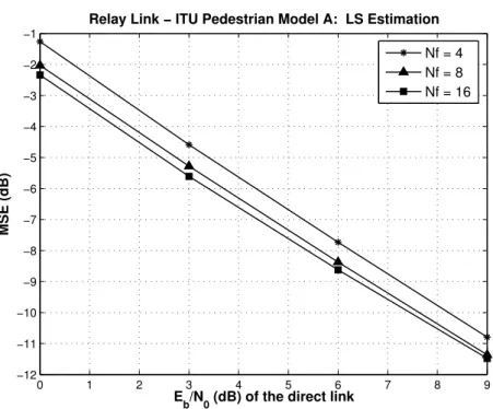
model A. . . 63 4.10 LS channel estimation performance for AF relay channel with ITU Pedestrian
model A. . . 64 4.11 LS channel estimation performance for point-to-point link with ITU Pedestrian
model A. . . 64 4.12 MMSE channel estimation performance for AF relay channel with ITU Pedestrian
model B. . . 65 4.13 MMSE channel estimation performance for point-to-point link with ITU Pedestrian
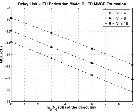
model B. . . 65 4.14 LS channel estimation performance for AF relay channel with ITU Pedestrian
model B. . . 66 4.15 LS channel estimation performance for point-to-point link with ITU Pedestrian
model B. . . 66 5.1 EF relay-assisted scenario. . . 71 5.2 Pilot Pattern. . . 73 5.3 Symbols arrangement per antenna element. . . 73 5.4 EF relay-assisted scenario: Block diagram. . . 74 5.5 Combining processing related to both transmission phases. . . 74 5.6 Symbols arrangement per antenna at the RN. . . 83 5.7 Equidistant and equipowered pilots. . . 83 5.8 Equidistant and non-equipowered pilots. . . 84 5.9 Equispaced and non-equipowered pilots and the corresponding CIR. . . 85 5.10 αkΓk per subcarrier. . . 85
5.11 MSE performance: Pilots with fluctuation in amplitude. . . 87 5.12 MSE performance: pilots with non-unitary yet constant values. . . 88 5.13 MSE performance: pilots with non-unitary yet constant values. . . 89 5.14 Maximum element off-diagonal of Rϑˆ˜ϑˆ˜. . . 91
5.15 System BER performance: Impact of using σt2 and σk,t2 . . . 94 5.16 System BER performance: Perfect channel knowledge and channel estimates. . 94 5.17 Channel estimation MSE performance: RA Scheme 2 ˆ 1 ˆ 1. . . 95 5.18 Channel estimation MSE performance: RA Scheme 2 ˆ 2 ˆ 1. . . 95 6.1 EF RA scenario. . . 99 6.2 EF RA system: Block diagram. . . 100 6.3 Pilot-Data aided Estimation: Block diagram. . . 103 6.4 Pilot-Data-aided estimation: Flow chart. . . 105 6.5 Pilot-Data channel estimation: MISO case. . . 108 6.6 Virtual pilots - Selection Processing. . . 109 6.7 Pilot-Data-aided estimation: Block-diagram. . . 110 6.8 MSE performance: Scenario #1 and ITU Pedestrian Model A. . . 114 6.9 MSE performance: Scenario #1 and ITU Pedestrian Model B. . . 115 6.10 MSE performance: Scenario #2 and ITU Pedestrian Model A. . . 115 6.11 MSE performance: Scenario #2 and ITU Pedestrian Model B. . . 116 x
6.12 MSE performance: Scenario #3 and ITU Pedestrian Model A. . . 116 6.13 MSE performance: Scenario #3 and ITU Pedestrian Model B. . . 117
List of Tables
3.1 Summary of LS implementation complexity (per symbol estimation) . . . 44 3.2 Summary of MMSE implementation complexity (per symbol estimation) . . . . 44 3.3 a and b vary according to a modulation scheme . . . 46 4.1 Simulation parameters . . . 60 5.1 Two transmit antenna SFBC mapping . . . 72 5.2 Simulation parameters . . . 92 6.1 Simulation parameters . . . 111 6.2 Assessed links statistics . . . 112
List of Symbols
• Choice of Notation
Regular small letters denote variables in the frequency domain whereas boldface small and capital letters denote vectors and matrices, respectively in the frequency domain as well. Variables, vectors or matrices in the time domain are denoted by p„q. All estimates are denoted by p^q.
Symbol Connotation
A Gain related to the AF protocol α Gain related to the EF protocol Bc Coherent frequency band
β Complex amplitude of a path c Light speed in vacuum cs Clutter size
CN i.i.d complex Gaussian Noise d Regenerated data symbol
d Superscript related to the data-aided estimation dt Distance between the transmitter and the receiver
D Regenerated data symbol matrix diagp¨q Diagonal matrix
detp¨q Determinant of a matrix ∆h Surface undulation
∆f Frequency shift
∆t Time shift
Eb Energy per bit
fD Doppler frequency
fDmax Maximum Doppler frequency
fk Frequency subcarrier
fs frequency spacing
Ft¨u Fourier transform
F´1t¨u Inverse Fourier transform
φ Angle between the direction of the motion and the path. G Number of antennas at the RN
G MRC equalisation coefficients h Channel frequency response ˜
h Channel impulse response
ı Imaginary unit
i Iteration index
I Identity matrix
j Data subcarrier
j Subset of data subcarrier J Size of the data subcarrier set J Data subcarriers set
J t¨u Bessel function
k Frequency domain subcarrier index K Number of subcarriers
l Channel path
L Number of channel paths
λ Wavelength
M M -ary constelation
m Number of encoded bits per symbol n Time domain sample index
n Variable index
N Set of the Natural numbers
N Number of time samples
Ncp CP size
Nf Pilot distance in frequency dimension
Nr Noise power
Nt CIR replica separation
Nv Pilot distance in time dimension
N0 One sided noise power spectrum density
p Pilot symbol
p Superscript related to pilot-based estimation P Size of the pilot subcarrier set
P Pilot subcarriers set
Ps Signal power
Q Number of antennas at the BS Q Q -function Rp∆tq Temporal autocorrelation Rp∆f q Spectral autocorrelation s data-symbol S soft-decision variable
SD Doppler power spectral density
σ2
ch Channel power
σh,l2 Average power of l-th path
σbu2 Noise variance related to the link BS-UT σbr2 Noise variance related to the link BS-RN σru2 Noise variance related to the link RN-UT σn2 Noise variance related to a generic link σt2 Noise variance of the overall noise
t Time instant
tcp CP duration
ts Data-symbol duration
tS OFDM symbol duration
Tc Coherent time
Ts Sampling interval
TS OFDM symbol duration with CP
τ Delay of a path
τmax Maximun excess delay
v Mobile terminal speed
W Filter FIR
x An OFDM symbol in frequency domain
y Received signal z Additive Noise ˝ Point-wise operation f Circular convolution } ¨ } 2-Norm | ¨ | Absolute value p¨q˚ Hermitian p¨qT Transpose x p¨q Estimate of p¨q Ă
p¨q p¨q in the time domain E ! ¨ ) Expectation operator xix
Chapter 1
Introduction
1.1
The Mobile Communications Journey
The breakthrough in wireless communications was the successful use of the electromagnetic waves for transmitting information, which allowed the long-distance transmission [1], [2]. The wireless communications has had a remarkable journey from the Marconi’s first experiments with radio communication in 1890’s to the cellular systems of nowadays.
Analogue cellular are referred to as the first generation of mobile communication systems, 1G, based on Frequency Division Multiple Access (FDMA) that was launched for voice service. In Japan the first operational cellular system was deployed by Nippon Telephone and Telegraph (NTT) in 1979, followed in Scandinavia by the Nordic Mobile Telephony (NMT) system in 1981. At the same year the Advanced Mobile Phone Service (AMPS) was introduced in North America by AT & T. In 1982 Total Access Communication System (TACS) was launched in the United Kingdom and afterwards, in 1985 the Radicom 2000 was introduced in France and the C-450 cellular system was introduced in Germany and Portugal. At mid 80’s with the advances in integrated circuits and digital communication the cellular systems, with rudimentary Quality of Service (QoS), based on analogue signalling techniques were becoming obsolete and the cellular service in Europe had several interoperable cellular systems [3].
The digital technology brought the opportunity to develop a second generation of mo-bile systems. The digital generation increased the capacity of the systems, spectral efficiency, provided better QoS and smaller mobile devices. In addition, the digital encryption provided secrecy and safety to the voice calls and data that were initially 9.6 kbp/s of peak data rates [4]. In order to develop a European-wide digital cellular standard the Telecommunication Com-1
2 1. Introduction
mission of European Conference of Postal and Telecommunications Administrations (CEPT) established a group of study called Groupe Speciale Mobile (GSM) that were in 1989 continued within the European Telecommunication Standards Institute European Telecommunication Standards Institute (ETSI). The second generation of mobile communication, 2G, deployed in the 90’s with the GSM standard built on Time Division Multiple Access (TDMA). Simul-taneous development of a digital cellular standard was done by Telecommunications Industry Association (TIA) in the USA yielding in the IS-54, also a TDMA-based standard, referred to as North American TDMA Digital Cellular or United States Digital Cellular. Later on, with revised standards, such a system has been renamed IS-136, often called D-AMPS, and with the development of a CDMA standard the IS-95 was completed by TIA in 1993. In Japan, a 2G TDMA standard was also developed, referred to as Pacific Digital Cellular (PDC). Shortly, the IS-95 CDMA system, marketed as CDMAOne, has been introduced in Japan as well. The 2G systems provided voice e-mail and the primary data service, Short Message Service (SMS), that is considered in all likelihood the most successful mobile service to date, after voice. In 2006 several countries have reached more than 80% cellular phone penetration and the global GSM subscribers counted more than 2 billion – 15 years after the launching of the its first network [5].
Higher data rates were later introduced in the 2G systems with the General Packet Radio Service (GPRS) that could provide rates from 56 kb/s up to 115 kb/s. Such rates could provide other services other than SMS such as Multimedia Messaging Service (MMS), Wireless Application Protocol (WAP), Internet access. Subsequently, similar services with data rates up to 384 kb/s could be provided by Enhanced Data Rates for GSM Evolution (EDGE) [6] that later on yielded into Evolved EDGE.
The third generation system, 3G, was a worldwide efforts to develop and deploy more ad-vanced cellular networks with a range of higher data rates multimedia communication such as person-to-person communication (push-to-talk over cellular, real time video sharing, voice over IP (VoIP) and online games) with high-quality images/ videos, Global Positioning Sys-tem (GPS) and access to information/ services whether on public or private networks with improved QoS. The Universal Mobile Telecommunication Services (UMTS) was developed as the 3G replacement for GSM therefore, UMTS is considered a synonymous with W-CDMA standard that is also referred to as IMT-2000 standard. W-CDMA higher-bandwidth radio
1.1 The Mobile Communications Journey 3
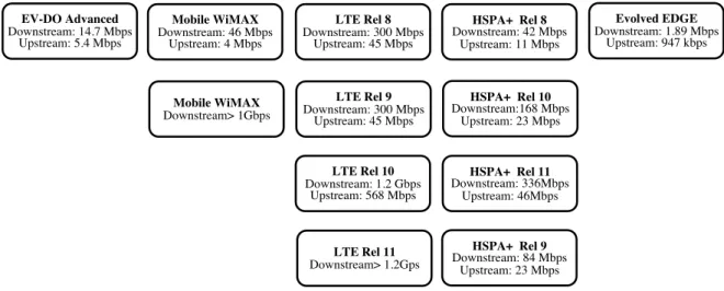
interface of Universal Terrestrial Radio Access (UTRA) was developed by the partnership project 3rd Generation Partnership Project (3GPP) whereas the CDMA2000 1 x Evolution-Data Optimized (EV-DO) Advanced standard, the 3G technology developed from the 2G CDMA-based standard IS-95, was developed by the 3GPP2. These standards projects were created in 1998 and 1999, respectively, as a collective effort of standardisation bodies in Eu-rope, Japan, South Korea, USA, and China with relevant International Telecommunication Union (ITU) recommendations [5], [7]. Figure 1.1 shows the evolution of the 3G wireless tech-nologies and their expected peak network performance capabilities, to date [8].
Evolved EDGE Downstream: 1.89 Mbps Upstream: 947 kbps HSPA+ Rel 8 Downstream: 42 Mbps Upstream: 11 Mbps LTE Rel 8 Downstream: 300 Mbps Upstream: 45 Mbps Mobile WiMAX Downstream: 46 Mbps Upstream: 4 Mbps HSPA+ Rel 9 Downstream: 84 Mbps Upstream: 23 Mbps HSPA+ Rel 10 Downstream:168 Mbps Upstream: 23 Mbps HSPA+ Rel 11 Downstream: 336Mbps Upstream: 46Mbps LTE Rel 9 Downstream: 300 Mbps Upstream: 45 Mbps LTE Rel 10 Downstream: 1.2 Gbps Upstream: 568 Mbps LTE Rel 11 Downstream> 1.2Gps EV-DO Advanced Downstream: 14.7 Mbps Upstream: 5.4 Mbps Mobile WiMAX Downstream> 1Gbps
Figure 1.1: Expected peak network performance capabilities.
Subsequent developments yielded into enhanced 3G networks. 3GPP specifications yielded into a radio access standard referred to as Long Term Evolution (LTE) and major exten-sions of the W-CDMA radio interface evolved High-Speed Packet Access (HSPA) evolution, also referred to as HSPA+. Other deployment with the Institute of Electrical and Electron-ics Engineers (IEEE) 802 family, that are the standards related to the broadband Wireless Metropolitan Area Networks (Wireless- MAN), within the Worldwide Interoperability for Mi-crowave Access (WiMAX) forum have led to the fixed WiMAX (802.16d-2004) and the mobile WiMAX (802.16e-2005) standards. The fourth generation system, 4G, was envisaged offering a seamless connectivity, i.e., the capability to roam across cellular networks, wireless LANs and WANs, satellites, and IP interoperability according to the user need. Currently, 4G network supports Multiple-Inputs and Multiple-Outputs (MIMO) and, to date, there three different
4 1. Introduction
types of 4G networks: LTE using Orthogonal Frequency-Division Multiple Access (OFDMA); HSPA+, sometimes using W-CDMA; WiMAX using OFDMA [9]. Current 4G applications include mobile telemedicine and monitoring, high-bandwidth mobile applications, mobile en-tertainment and multi-party games. According to ITU the 4G term is undefined however, it applies to technologies beyond IMT-2000 or evolved 3G technologies providing a substantial level of improvement in performance and capabilities with respect to the initial third genera-tion systems [10]. ITU refers to technologies beyond IMT-2000 as IMT-Advanced which the response from 3GPP evolved the LTE-Advanced (LTE-A), Release 10.
The smartphones has become a focal point for many people’s digital lives, displacing the PC as the primary means of accessing the Internet [11]. Worldwide, the total number of smartphones is expected to exceed 3 billion by 2017 and as the cost of cellular devices decrease and their functionality increases, it is expected that the vast majority of people will hold in their hand a device with higher processing power than the most powerful computers from the 1980’s [12].
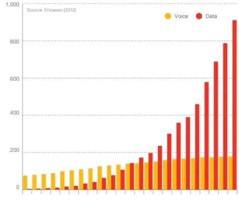
Whilst voice remains as the basic service offered by the worldwide mobile operators the data traffic, which has been driven by the diffusion of smart devices and apps, has been growing at an impressive rate between 2007 and 2012, according to the Figure 1.2 that depicts the total monthly traffic split for voice and data1. The data traffic doubled between Q3 2011´Q3 2012 and the quarterly growth between Q2 2012´Q3 2012 was 16 percent [13].
Mobile data traffic is expected to grow approximately 14 times between 2012 and 2018 as it continues the trend of doubling each year, according to the Figure 1.3. The smartphone traffic is expected to grow faster due to the high growth in subscriptions. In the latter years of the forecast period, the data traffic will be split fairly equally between mobile phones on one hand and mobile PCs, tablets and mobile routers on the other [13].
1
1.1 The Mobile Communications Journey 5
Figure 1.2: Global total traffic in mobile networks, 2007 ´ 2012, from Traffic and Market Data Report, Ericsson, 2012.
Figure 1.3: Global mobile traffic: voice and data 2010 ´ 2018, from Traffic and Market Data Report, Ericsson, 2012.
6 1. Introduction
Nowadays 4G connections represent only 0.2% of mobile connections, they already account for 6% of mobile data traffic, to date. In 2016, 4G is expected to represent 6% of connections, but 36% of total traffic. To date, a 4G connection generates 28 times more traffic than a non-4G connection as many of the 4G connections today are for residential broadband routers and laptops, which have a higher average usage. In addition, the higher speeds encourage the adoption and usage of high-bandwidth applications, therefore a smartphone on a 4G network is likely to generate 50% percent more traffic than the same model smartphone on a 3G network [14].
According to the predictions, in the end of 2012 the total number of mobile subscriptions was around 6.6 billion, being 1.5 billion of broadband connections. By the end of 2018 total mobile subscriptions are predicted to reach 9.3 billion, being 1.5 billion of broadband accesses. These figures do not include Machine-to-Machine (M2M) subscriptions, which will also add to the number of subscriptions [13].
In order to satisfy the peak data rate of 100 Mb/s for high mobility and 1 Gb/s for low mobility required by the IMT-Advanced as well as the roaming seamlessly between networks [15], [16], promising approaches have been foreseen for the LTE-A, such as:
‚ Relaying: Additional nodes are included in the communication link in order to exchange information and improve link reliability.
‚ Carrier Aggregation: Multiple component carriers of smaller bandwidth are aggregated. It is an attractive alternative to increase data rate. Aggregating non-contiguous carriers, fragmented spectrum can be more efficiently utilised in various deployment scenarios [17]. ‚ Multi-user MIMO (MU-MIMO): Spatial diversity is exploited by serving different users on different spatial streams on the same time/frequency resource, that is, assigning the same resource block to different users.
‚ Coordinated MultiPoint (CoMP) Transmission: It refers to the possibility to coordi-nate the transmission towards the same user adopting multiple base stations, in case of downlink transmission. CoMP techniques imply into use resource allocation techniques, coordination and synchronisation in order to cope with multi-point transmissions [18]. ‚ Scheduling in Heterogeneous Networks: It addresses radio resource management
1.2 Motivations and Goals 7
means of dynamic spectrum access [19].
Whilst LTE was initially designed to be as decentralised as possible, in LTE-A enhanced Intercell Interference Coordination (ICIC) [20] is now being introduced such that interference-related information is exchanged among base stations and resource usage decisions are per-formed in a hierarchical manner.
Further standardisation of LTE-A will continue to follow the evolutionary phases in the form of releases. The future steps towards such an evolution is expected to lead to the LTE-B, LTE-C and so on in order to indicate the steps after LTE-A [21].
1.2
Motivations and Goals
As referred in the previous section, in order to continuously provide the demand for wireless services and ubiquitous access, more innovative techniques should be considered. In LTE-A and WiMAX standards cooperative techniques as well as virtual MIMO and Space Frequency Block Code (SFBC)/Space Time Block Code (STBC) are regarded in order to cope with the IMT-Advanced requirements.
When it comes to virtual MIMO or Relay Assisted (RA) techniques, a new paradigm arises, i.e., instead of having a point-to-point link between the transmitter and the receiver the connection may involve several nodes and this raises new challenges in channel estimation. The availability of accurate channel estimates is crucial to the performance of any link and, although there is abundant literature in the context of point-to-point links, when multiple links are involved (e.g. through the relays), these techniques require modifications and few studies have been done to date. Therefore, efficient channel estimation techniques for RA cooperative schemes are needed.
The estimation of a channel involving relays has been addressed for several scenarios and protocols, e.g., for the Decode-and-Forward (DF) protocol the relaying channel is regarded as two point-to-point channels whereas for the Amplify-and-Forward (AF) a compound channel estimate is addressed. Regarding RA scenarios where the Relay Node (RN) is equipped with a single antenna and employs the AF relaying protocol, some channel estimation techniques have been proposed, as mentioned in the following chapters. Nevertheless, restricting the RN to a single antenna is a limitative approach since the diversity associated with multiple antennas is
8 1. Introduction
not explored. When it comes to a scenario where the RN is equipped with an antenna array, the available literature is scarce, specially concerning the used transmission/reception scheme. This thesis addresses Orthogonal Frequency-Division Multiplexing (OFDM)-based systems employing RA cooperative approaches. It aims at: identifying the impact that the RN has on the estimation performance as well as its constrains; contributing with efficient channel estima-tion schemes for RA scenarios such that at the RN low complex processing are performed and the diversity provided by antenna array is achieved; proposing and assessing techniques with aid of the regenerated data-symbols, as virtual pilots, in order to compensate the impairments brought by the RN insertion.
1.3
Main Contributions and Dissemination
The main contributions of this thesis is summarised as follows:
‚ Proposal of a pilot-based channel estimation scheme for RA cooperative systems em-ploying the Equalise-and-Forward relaying protocol;
‚ Proposal of a pilot and data aided channel estimation method for an EF MIMO coop-erative using Alamouti coding;
‚ Proposal of a modified MMSE channel estimator for RA cooperative systems employing the Amplify-and-Forward relaying protocol;
‚ Assessment of the aforementioned proposals in realistic scenarios with ITU multipath channel models including evaluation of the impact of pilot density in the performance the RA cooperative systems;
The contributions presented in this thesis were disseminated in the following scientific publications.
‚ (J1) D. Neves, C. Ribeiro, A. Silva, and A. Gameiro. An Iterative Pilot-Data-Aided Estimator for SFBC Relay-Assisted OFDM-Based Systems. EURASIP Journal on Ad-vances in Signal Processing, 2012:74, 2012.
1.4 Thesis Organisation 9
‚ (B1) D. Neves, C. Ribeiro, A. Silva, and A. Gameiro. Channels and Parameters Acquisi-tion in Cooperative OFDM Systems. In Vehicular Technologies: Increasing Connectivity. Intech, 2011.
‚ (C1) D. Neves, C. Ribeiro, A. Silva, and A. Gameiro. An Iterative Pilot-Data Aided Estimator for OFDM-Based Relay-Assisted Systems. In Proceedings of IEEE Third Latin-American Conference on Communications, Belem, Brazil, October 2011.
‚ (C2) D. Neves, C. Ribeiro, A. Silva, and A. Gameiro. A Pilot-Data Based Channel Estimation Method for OFDM Relay-Assisted Systems. In Proceeding of IEEE Vehicular Technology Conference - Fall, San Francisco, United States, September 2011.
‚ (C3) D. Neves, C. Ribeiro, A. Silva, and A. Gameiro. A Time Domain Channel Estima-tion Scheme for Equalize-and-Forward Relay-Assisted Systems. In Proceeding of IEEE 72nd Vehicular Technology Conference - Fall, Ottawa, Canada, September 2010.
‚ (C4) D. Neves, C. Ribeiro, A. Silva, and A. Gameiro. Channel Estimation Schemes for OFDM Relay-Assisted Systems. In Proceeding of IEEE 69th Vehicular Technology Conference - Spring, Barcelona, Spain, April 2009.
1.4
Thesis Organisation
The remaining of this thesis is organised in seven chapters that present the contributions of the work and directions for future research.
Chapter 2 presents the concepts related to the wireless medium such as the mechanisms of propagation, channel modelling as well as the channel characterisation. The basic principles of OFDM-based transmission are presented as well as the concept of diversity in wireless communications, RA cooperative systems and some relaying protocols are described.
Chapter 3 addresses the channel estimation related issues such as pilot density and pilot pattern as well as their impact on the estimation performance. The conventional pilot-based channel estimators are addressed, following by the OFDM pilot-based transmission and as-sumptions that are considered in this thesis. In addition, the metrics carried out throughout of the evaluation of overall system performance are also presented.
10 1. Introduction
Chapter 4 presents the mathematical model for the RA cooperative system employing the AF protocol and the corresponding relay channel statistics. Also, the proposals for modifying the classical point-to-point estimators, according to the AF relaying channel statistics, are presented and it is discussed the impact of the pilot density on the relaying channel estimation performance.
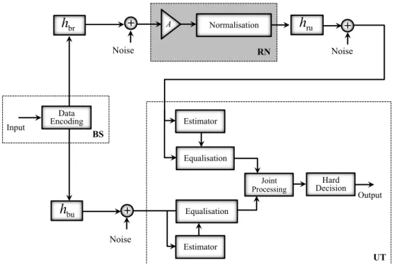
Chapter 5 addresses the mathematical model for RA cooperative scenarios employing the Equalise-and-Forward (EF) protocol, where in one of them the RA MIMO cooperative transmission is complemented by the use of Alamouti coding. A pilot-based channel estimation scheme is proposed in order to provide the required relaying channel estimates and other parameters that may be useful in the equalisation processing at the User Terminal (UT).
Chapter 6 presents an iterative pilot and data-aided channel estimation method for an EF MIMO cooperative scenario. The performance of the channel estimation scheme, presented in Chapter 5, is improved by using the energy of the regenerated data symbol. In addition, it is assessed the impact of the pilot density in the relaying channel estimates performance.
Chapter 7 summarises the findings and provides directions for future works exploiting the concepts addressed by the this thesis.
This thesis was written as a comprehensive complement to the published papers that contain most of the information. All the numerical simulations were carried out through Monte-Carlo simulations in a simulation platform implemented in Matlab R programming language.
Chapter 2
Basic Principles of Wireless and
Cooperative Communications
This chapter discusses aspects of cooperative communication and relaying capabilities. The channel modelling, OFDM-based systems and the assumptions considered throughout this work are discussed as well.
2.1
Wireless Medium
In wireless systems the signal, i.e., the electromagnetic wave, propagates through free space and through or through off the objects cluttered in the surrounding the environment, there-fore, the term wireless channel refers to the medium between the transmitting and receiving antenna. Since the propagation of signal leads to distortions, delays and losses, the space-time-frequency characteristics of the wireless channel play an important role in the system performance.
2.1.1 Propagation: Mechanisms and Effects
Depending on the relationship between the radio-frequency signal wavelength λ, the dis-tance between transmitter and receiver dt, the clutter size cs and its surface ripples ∆h, the mechanisms of propagation are categorised according to the following.
‚ Free space propagation: There is no clutter between the transmitter and receiver, i.e., the signal propagates through the Line-of-Sight (LOS). This propagation obeys the Friis’ transmission formula [22].
12 2. Basic Principles of Wireless and Cooperative Communications
‚ Reflection and refraction: A part of the signal reflects off the clutter’s surface, if λ " ∆h, and the remaining part refracts into the clutter, if cs" λ. Both are represented in Figure 2.1 a).
‚ Diffraction: Occurs when, between the transmitter and receiver, there is no LOS and the clutter has edges that are smaller or of the same size of λ. The diffraction causes the formation of secondary waves that can still reach a zone shadowed by an object, according to Figure 2.1 b).
‚ Scattering: It is due to the constructive and destructive addition of the reflected waves off surface elements of heights differing of ∆h. If csě λ and λ « ∆h the signal is known to be scattered off the clutter’s surface, represented in Figure 2.1 c).
Reflection
Refraction Diffraction Scattering
a) b) c)
Figure 2.1: Reflection, refraction, diffraction and scattering propagations.
A signal may undergo all these propagations mechanisms before coupling into the receive antenna. Consequently, these phenomena may lead to the following distortions, depicted in Figure 2.2.
‚ Multipath Propagation: The signal and its copies, i.e., the replicas, transverse multiple propagation paths such that the received signal corresponds to a sum of signals with different delays, amplitude, phase angle of arrival and therefore this effect causes fading to the signal. If the multiple paths change rapidly this effect is referred as fast-fading. ‚ loss: It corresponds to the attenuation of the signal power with the distance.
Path-loss limits interference but also rapidly diminishes the useful signal power [23].
‚ Shadowing: It is caused by obstructions between the transmitter and receiver and it is also referred as shadow loss. Likewise the path-loss effect, it is noticeable over long distances and it leads to fluctuations in the average received signal power.
2.1 Wireless Medium 13
The fluctuation in the signal power caused either by path-loss or shadowing can be com-pensated by techniques provided by network planners [24]. Therefore, in this thesis it is considered that the multipath is the only effect distorting the transmitted signal.
Multipath Path-loss Shadowing
Source
Destination
Figure 2.2: Multipath, path-loss and shadowing effects.
2.1.2 Channel Modelling
In the designing process of wireless systems the channel model is a key aspect as it influence the performance behaviour, power budget dimensioning and transceiver design.
Regarding the channel models, there are statistical, deterministic and hybrid channel mod-ellings [3]. The statistical model considers random variables in order to describe the channel behaviour. The deterministic one is based on the electromagnetic wave propagation whereas the hybrid model is obtained based on indoor or outdoor measures and mathematical ap-proximations. The statistical model is commonly used in literature due to its low complex implementation and hence it is considered in this thesis.
According to the statistical model, the multipath fading channel can be characterised as complex-valued, time variant, low-pass equivalent Channel Impulse Response (CIR) given by [?] ˜ hpt, τ q “ L´1 ÿ l“0 βlptqδpt ´ τlq, (2.1)
14 2. Basic Principles of Wireless and Cooperative Communications
The Channel Frequency Response (CFR) corresponds to Fourier Transform (FT) of Eq. (2.1) w.r.t. τ and corresponds to hpt, kq “ L´1 ÿ l“0 βlptqe´ı2πkτl. (2.2) 2.1.3 Channel Characterisation
The channel can be statistically characterised according its temporal and spectral prop-erties. The behaviour of the channel impacts the transmitted signal and therefore, the au-tocorrelations functions dependent on CIR and CFR play an important role in the system performance.
2.1.3.1 Spectral Domain
The spectral autocorrelation function determines how correlated the channel is after an observation frequency shift of ∆f . It is expressed by
Rp∆f q “ E thpf qh˚ pf ` ∆f qu “ L´1 ÿ l“0 σh,l2 σ2che ´ı2π∆f τl, (2.3)
where σh,l2 is the average power of l-th path, i.e., σ2h,l “ E !
|βl|2
)
and σch2 is the total power average which is given by σch2 “řL´1l“0 σ2
h,l.
The Inverse Fourier Transform (IFT) of the spectral autocorrelation function gives the average power of the multiple delayed replicas, i.e., the Power Delay Profile (PDP), which determines how dispersive a channel is [23]. The dispersion of the channel is characterised by the Root Mean Square (RMS) delay spread τRMS which corresponds to the second central moment of the PDP, according to the following expression.
τRMS “
b Ě
pτ2q ´ p¯τ q2, (2.4)
with ¯τ being the the first moment of the PDP, i.e., the average delay ¯τ “ř
lσh,l2 τl{ ř lσ2h,land s τ2“ř lσ2h,lτl2{ ř
lσh,l2 . In this thesis, the total power average is assumed to be normalised to
2.1 Wireless Medium 15
The spectral autocorrelation function characterises whether a channel is frequency selective or flat fading. Such a characterisation depends of the coherent frequency band Bc which corresponds to the shift ∆f over which Rp∆f q remain unchanged or insignificantly changed, i.e., it is a range of frequency where the multipath channel affects the transmitted signal with similar gain and linear phase. The coherence frequency band depends on the environment through its impact onto the PDP. The literature presents several numerical approximations to Bc [3],[25],[26]. Generally, it is considered inversely proportional to the maximum excess
delay τmax, i.e., the time interval between the last resolvable tap and the earliest significant one, that is Bc« 1{τmax.
Considering the transmitted signal bandwidth B, if B ă Bc all the spectral components
of the signal are affected by the same attenuation and by a linear change of phase. In such a case, the channel is classified as flat fading or narrow band channel. If B ą Bc, then the
spectral components of the signal are affected by different attenuations, making it harder to equalise the received signal for accurate detection [26]. In this case, the channel is classified frequency selective fading or broadband channel.
2.1.3.2 Temporal Domain
The temporal autocorrelation determines how correlated the channel is after an observation time shift of ∆t. The temporal autocorrelation depends on the environment and the movement of transmitter and/or receiver. Such a mobility makes the channel time-variant and hence, makes the signal may be perceived at a different frequency than the actual emitted. This effect is referred as Doppler shift and the perceived frequency is called Doppler frequency fD.
The normalised temporal autocorrelation function is expressed as [3]
Rp∆tq “J0p2πfDmax∆tq, (2.5)
where J0 is the zero order Bessel function of the first kind and fDmax corresponds to the maximum Doppler frequency that is obtained for φ “ 0 or φ “ π, according to the following expression.
fD “
v λk
16 2. Basic Principles of Wireless and Cooperative Communications
where v is the speed of motion, either of transmitter or receiver, λk is the corresponding
wavelength of the carrier and φ is the angle between the direction of the motion and the path. Signals undergoing different paths experience different Doppler shifts and therefore, the received signal power spectral density is spread over the bandwidth limited by the fDmax. The FT of the temporal autocorrelation corresponds to the Jakes spectrum [24], also referred as Doppler Power Spectrum Density (PSD) SD which is
SDpfDq “ $ ’ ’ & ’ ’ % 1 πfD b 1 ´ p fD fDmaxq , |fd| ď fDmax 0, remaining . (2.7)
The temporal autocorrelation function categorises whether a channel is slow or fast fad-ing. Such categorisation depends on the the coherent time Tcwhich is the shift ∆t over which
Rp∆tq remains invariant, i.e., the channel impulse response remains insignificantly unchanged. Similarly to the frequency coherent band, the literature presents several numerical approxi-mations to Tc[3]-[26]. Generally, it is considered inversely proportional to maximum Doppler
frequency, that is Tc« 1{fDmax.
Considering the transmitted signal duration tS, if tS ą T c the channel impulse response
changes over a period of time longer than the signal duration. In such case, the channel is categorised as slow fading. If the converse applies, the channel is said to have fast fading [26]. The channel modelling previously described is classified as Wide Sense Stationary Uncor-related Scattering (WSSUS) since neither the coherence time or frequency depend on time and since the paths presents uncorrelated scattering. If the multipath fading channel is only made up of non-LOS components, which is a common assumption in urban scenarios, the en-velope of the channel is Rayleigh distributed and the channel is said Rayleigh fading channel [27]. In cases where there is a dominant scatter in the medium, e.g. a LOS component, the en-velope of the channel is described by a Rice distribution and the channel is said to be Ricean fading channel [27].
2.2 OFDM-based Systems 17
2.2
OFDM-based Systems
In single carrier modulation techniques, a carrier occupies the entire bandwidth whereas in multi-carrier techniques each carrier occupies a small part of it. OFDM can be address as a special case of a multi-carrier technique that modulates independent data on several orthogonal and overlapped subcarriers therefore, the available bandwidth is efficiently used.
Let us consider a digital multi-carrier transmitter with K subcarriers where Ts is the sampling interval, i.e., t “ nTs for n “ 0, 1, ¨ ¨ ¨ , N ´ 1. sk corresponds to a complex
data-symbol generated by a modulation scheme. Each sk is modulated according to a frequency fk, therefore, the multi-carrier transmitter output is given by
˜ spnTsq “ K´1 ÿ k“0 skeı2πfknTs. (2.8)
A multi-carrier transmitter consists of a bank of modulators and for complexity and costs reasons such a structure is not appropriate for actual implementation.
Considering that k “ 0, 1, ¨ ¨ ¨ , K are the indices of the baseband frequencies that are uniformly spaced in frequency domain by a frequency spacing of fs, such that fk “ kfs.
Then, assuming that fs“ 1{pKTsq is the minimum separation among the subcarriers in order
to make them orthogonal, thus Eq. (2.8) can be written as
˜ sn“ ˜spnTsq “ K´1 ÿ k“0 skeı2πnk{K. (2.9)
Equation (2.9) corresponds to an OFDM signal. Except for the missing multiplying factor 1{?K, it corresponds to the equation of a K-point Inverse Discrete Fourier Transform (IDFT). If K is power of two, it can be implemented by a Inverse Fast Fourier Transform (IFFT) which means that OFDM allows low-complexity and computationally efficient implementations [26], [4] and a bank of parallel modulators is no longer required.
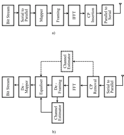
In Figure 2.3 is shown a representative block diagram of an OFDM baseband system where K represents the number of subcarriers, for k “ 0, 1, ¨ ¨ ¨ , K, and the corresponding bandwidth is B “ Kfs. This system presents the components that are relevant to the purpose of this
18 2. Basic Principles of Wireless and Cooperative Communications Bi t S tre am S eri al to P ara ll el M appe r IF F T CP Ins ert ion P ara ll el to S eri al CP Re m ova l FFT S eri al to P ara ll el E qua li se r D e -M appe r Bi t S tre am a) b)
Figure 2.3: OFDM System. a) Transmitter. b) Receiver.
In the transmitter, the Serial to Parallel block arranges the serial bit stream into parallel lower rate bits. In the Mapper block, sets of parallel bits are mapped into complex constel-lation points, i.e., data-symbols, according to a constelconstel-lation. In the IFFT block, at time K subcarriers moulds the amplitude and phase of K data-symbols. The output of this block corresponds to an OFDM symbol vector ˜x that is made up of N elements, according to
˜ sn“ 1 ? K K´1 ÿ k“0 skeı2πnk{K, for n “ 0, 1, ¨ ¨ ¨ , N. (2.10)
Since each data-symbol has period of ts hence, an OFDM symbol period is tS “ N ts.
Considering that the duration of an OFDM symbol corresponds to the inverse of the frequency spacing and the orthogonal subcarriers follows fs “ 1{pKTsq, the sampling interval can be
express as
Ts“
ts
K. (2.11)
OFDM systems may suffer sever interferences that may compromise the system perfor-mance. The high speed motion may destroy the orthogonality leading to power leakage among the subcarriers, referred as Inter-Carrier Interference (ICI). Also, the delay of the received signals makes an OFDM symbol disturbs the subsequent one generating Symbol Inter-ference (ISI). In order to mitigate ISI, a Cyclic Prefix (CP), i.e., a copy of the last samples of the corresponding upcoming symbol, should be inserted between the symbols. Inserting a CP with duration equal or higher than the maximum delay guarantees ISI free and allows the channel matrix to be circular so that it prevents ICI. It should be pointed out that the
asyn-2.3 Diversity in Wireless Communications 19
chronism between the received signal and the local oscillator at the receiver can cause ICI as well. A long enough CP and perfect synchronisation are common requirements of a system free of ISI and ICI.
The CP is inserted by the CP Insertion block resulting in N ` Ncp samples with period of
TS “ tS` tcp where tcp is the period of the corresponding Ncp, the size of the CP.
In the receiver side, Figure 2.3 b), after remove the CP the OFDM symbol is brought into the Frequency Domain (FD) by the Fast Fourier Transform (FFT) block. The Equaliser block is designed to mitigate distortions introduced by the channel, assuming that this block can access the channel estimates. Without the equalisation, if no noise was considered, the bit stream could not be recovered. The optimal equaliser is the Maximum Ration Combining (MRC) [26] and its coefficients correspond to the complex conjugate of the CFR. Following the equalisation at the De-mapper block the demodulation takes place and the the bit stream is recovered.
In contrast to Figure 2.3 OFDM systems can also be implemented with the block Serial to Parallel before the IFFT at the transmitter and with the Parallel to Serial following the FFT block at the receiver [3],[28]. Without loss of generality, the OFDM modulator generates the same result.
2.3
Diversity in Wireless Communications
Diversity corresponds to transmitting additional copies of a signal over multiple uncor-related paths, each one exhibiting a fading process as much independent from the others as possible. Such a transmission improves the overall links’ reliability and leads to diversity gains. Techniques that aim at providing multiple and independent signal paths are known as diversity techniques [28]. Such techniques may mitigate the fading effects of the multipath channel, basically by ensuring multiple channels that vary in time, frequency, space or po-larization. The deployment of multiple antennas inducing space diversity generates copies of the transmitted signal at the transmitter and/or receiver. The benefits of diversity are sig-nificant, but they can be summarized by the performance improvement that is manifested by the communication symbol error probability Pser decreasing at a much larger rate at a high channel Signal-to-Noise Ratio (SNR) than systems with less or no diversity, according to the
20 2. Basic Principles of Wireless and Cooperative Communications expression D0“ lim SNRÑ8 log Pser log SNR. (2.12)
The diversity gain stem from the fact that with the amount of additional copies increasing, the probability of all of them being illegible decreases. According to Eq. (2.12), for a high value of SNR a large diversity gain means that the probability of symbol error is reduced at a faster rate [28] hence, the chance that there is at least one sufficiently strong path is improved. In the following, is described the main diversity techniques.
‚ Time Diversity: Multiple copies of the signal are transmitted at different times instants. The interval between the transmissions should be greater than the coherence time of the channel therefore, the copies experience channel realizations that are highly uncorrelated, i.e., independent fading.
‚ Frequency Diversity: Copies of the signal are transmitted using different carriers. If the frequency spacing between the carrier frequencies is greater than the channel frequency coherence band, the received signals would suffer from uncorrelated fading.
‚ Space Diversity: Also referred as antenna diversity it corresponding to either transmit or receive, or both, copies of the signal over uncorrelated propagation paths by using multiple and physically separated antennas.
‚ Space-time or Space-frequency diversity: The space diversity could be increased by its combination with a frequency diversity or a time-diversity method, generating the spatial diversity and thus increasing the frequency and time selectivity of the resulting channels. ‚ Polarization Diversity: Copies of the signal are transmitted and received via antennas
with orthogonal polarisation.
Furthermore, multiple diversity techniques can be combined to provide even greater per-formance improvement. These translates into decreasing transmission powers, higher capacity or better cell coverage [28].
Alternatively, diversity may be achieved by using a third terminal, a helper node, it is so called cooperative diversity. This form of diversity uses the broadcast nature of the wireless channels and the available or idle nodes willing to cooperate within a wireless network.
2.4 Cooperative Communications 21
The cooperative network can be regarded as a system implementing a distributed multiple antenna in order to create diverse signal paths, as depicted in Figure 2.4, where node U cooperates with neighbours to send information to B.
B
U
Figure 2.4: Cooperative transmission.
Similarly to the space diversity case, in such a diversity as the number of cooperating nodes increases the diversity increases as well.
2.4
Cooperative Communications
MIMO communications can improve the system throughput and reliability based on space diversity. The concept of transmitting information over different antennas is behind of the MIMO techniques and such approaches provide very higher data rates in comparison with Single-Input and single-output (SISO) or Multiple-Inputs and Single-Output (MISO) tech-niques. In order to make use of the MIMO advantages the devices should be equipped with multiple antennas and they should experience independent channel characteristics, i.e., the equivalent channel matrix should be full-rank. In practice, MIMO devices may experience propagation environment that cannot support MIMO requirements, i.e., the paths between transmitter and receiver may be highly correlated [28]. The use of an extra source, distant several wavelengths from the primary one, makes the relay channel, e.g. Base Station (BS)-RN-UT or UT-RN-BS, varies independently from the direct channel, e.g. BS-UT or UT-BS. This may generate a full-rank channel matrix between the sources and receiver.
22 2. Basic Principles of Wireless and Cooperative Communications
had introduced the three-terminal relay channel and the information theoretic properties of the relay channel, respectively. Later on in [31] an user cooperation protocol was suggested in order to boost the uplink capacity and in [32]-[33] a two user cooperation system was proposed such that pairs of terminals in the wireless network are coupled to help each other forming a distributed two-antenna. Cooperative communications is a new paradigm shift for the future wireless systems that will guarantee high data rates to all users in the network, and we anticipate that it will be the key technology aspect in the forthcoming wireless networks [28]. The key aspect in cooperation is sharing the resources among multiple nodes in a network and plenty of lessons have been learned ever since and current standards developing bodies are picking up on the relaying and the cooperative concept. The IEEE 802.16j standard [34] has developed a relay enabled mode to WiMAX in the hope of giving it a competitive edge in 3GPP LTE developments and the LTE-A includes cooperative relay features in order to extend coverage by means of relay nodes [15],[35].
Cooperative receivers consider the information received by the direct and the multi-hop links. On account of that, cooperative communications offers several advantages such as:
‚ Extend the coverage area
‚ Reduce battery consumption and extend network lifetime ‚ Improve system performance and capacity
‚ Increase the throughput and stability region for multiple access schemes
‚ Provide cooperation trade-off beyond source–channel coding for multimedia communi-cations
‚ Infrastructure-Less Deployment: The use of relays allows the roll-out of a system that has minimal or no infrastructure available prior to deployment. Relaying can be used to facilitate communications even though the cellular system is non-functioning, e.g. in disaster struck areas. For hybrid deployments, that is a cellular system coupled with relays, the deployment and maintenance costs can be lowered [23].
The "Anyone, Anywhere and Any time" paradigm fits perfectly the cooperative communi-cations. Any terminal, static or mobile, can act as a RN or make use of relay link and therefore can provide or obtain higher gains as cooperative entity than as autonomous terminal.
2.4 Cooperative Communications 23
2.4.1 Cooperative Systems
In wireless communications, initially, relay-assisted communication was designed to gen-erate virtual antennas for single-antenna devices in a multi-user environment. The concept of cooperation has been extended to antenna arrays devices in order to merge benefits from space and cooperative diversity. In cooperative scenarios the receiver, e.g. UT, may combine the signal transmitted by two sources: the source, e.g., BS and a helper node, a RN. This ap-proach has major impact especially in devices where the integration of more antennas is not suitable either for size or power constraints.
In non-cooperative systems the simplest channel corresponds to a point-to-point one, ac-cording to Figure 2.5. Such channels present significant attenuation of the signal with distance, which makes them impractical in long-range communications. The simplest form of user co-operation is multi-hopping that corresponds to a chain of point-to-point links from the source to the destination, according to Figure 2.6 where is depicted a two-hop link.
Source Destination
Figure 2.5: Point-to-point link.
Destination Source
Relay
Figure 2.6: Two-hop link.
Such links represent scenarios where the direct link is shadowed by the clutter or offers poor conditions compared to the relay channel. The WiMAX standards has included the relay enable mode since 2009 [34],[36] in order to leverage coverage problems however, they act as repeater not as cooperative entities. Since, at least, one helper node is included the cooperative communications no longer have a point-to-point links but instead they have a
24 2. Basic Principles of Wireless and Cooperative Communications
multi-links from the transmitter to the receiver, according to Figure 2.7 that depicts a three-terminal relay link.
Source Destination
Relay
Figure 2.7: Three-terminal relay link.
Furthermore, the two-hop channel in Figure 2.6 can be extended by including more than one helper node, as depicted in Figure 2.8. Optimally designed cooperative schemes that involve µ terminals can achieve µ-th order diversity.
Destination Source
Relay #1 Relay #µ
…
Figure 2.8: Multiple relay scenario.
2.4.2 Relaying Protocols
The cooperation is enabled by a relaying protocol that establish the processing to be per-formed at the RN. A protocol is termed as half-duplex when the reception and transmission are processed in different phases, i.e., different times in the same band, otherwise they are referred as full-duplex and the transmitted/received signals must be orthogonal. In real sys-tems is difficult to ensure enabling simultaneous transmission and reception in the same band since the transmitted signals could cause severe interference to the incoming signals.
The-2.4 Cooperative Communications 25
oretically, the relay could cancel out the interference since the transmitted signal is known however, errors in interference cancellation could compromise the received signal. Due to the difficulty of accurate interference cancellation it is more common using half-duplex protocols. Nevertheless, advances in analogue processing could potentially enable full-duplex relaying [37].
The half-duplex protocols, as depicted in Figure 2.9, present two phases:
t Broadcasting Forwarding Phase 1: t1 Phase 2: t2 Idle S ourc e Re la y N ode t
Figure 2.9: Half-duplex relaying protocols.
‚ Phase 1: The BS broadcasts the signal. The UT keeps the received signal in a buffer whereas the RN processes it.
‚ Phase 2: The RN forwards the signal and the BS may remain idle. At the UT the signals received in both phases are combined in order to be hard decoded.
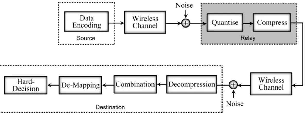
The relaying protocol also can be classified as transparent or regenerative. The later one requires digital baseband operations therefore, considering the involved links with comparable conditions, they are likely to outperform the transparent ones [37]. Transparent relaying essentially implies that the relay does not access the information contents but receives the signal in one frequency band, performs analogue changes to it and momentarily retransmitted on another frequency band [28]. Some relaying protocols are described in the following.
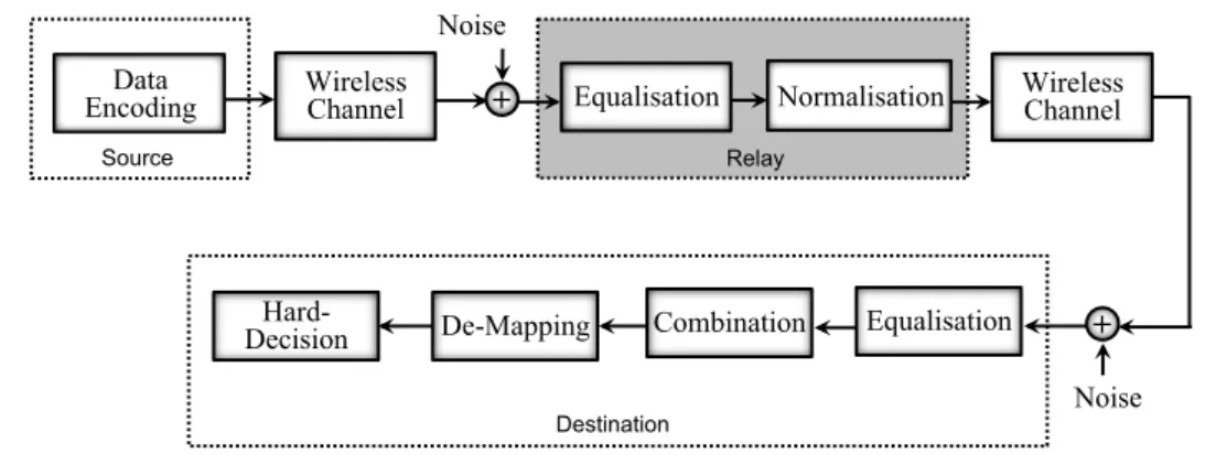
‚ AF: The RN scales the signal received from the BS. The Normalisation block normalises the amplified signal before transmitting it to the UT. It is described in Figure 2.10, where
26 2. Basic Principles of Wireless and Cooperative Communications
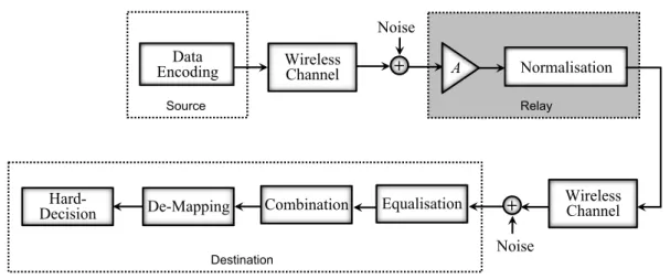
A corresponds to the amplification factor [38]. The amplification gain may follow three choices: constant, average or variable. In the first case, the relay node transmits at a constant output power that has been set during the node manufacturing. In the second choice, the relay fixes the amplification factor over a given time widow to a value that depends on long term statistics in the channel. In the third case, the amplification gain is adapted to instantaneous changes in the channel or network. The major disadvantage of this protocol is the amplification of the noisy components.
Noise Wireless Channel + Data Encoding A Normalisation Wireless Channel Relay Equalisation Source Combination Hard-Decision Destination De-Mapping Noise +
Figure 2.10: Block diagram of the cooperative link with the RN employing the AF protocol.
‚ DF: The received signal is hard-decoded, re-encoded and then transmitted to the UT, according to Figure 2.11 [39]-[40]. Since this protocol decodes the received signal it has the advantage over the AF in reducing the effects of the noise. If the channel source-relay offers excellent conditions, this protocol achieves optimal performance. However, if the first hop of the channel presents poor conditions it entails the possibility of forwarding erroneously detected signals to the destination, causing error propagation. An effective approach of this protocol is referred as Selective DF. According to it, the relay only processes the signal if its SNR excess a certain threshold. If the SNR falls below the threshold, the relay idles. Such approach overcome the problem in DF relaying in which the relay forwards all decoded signals to the destination although some decoded signals are incorrect.