UNIVERSIDADE FEDERAL DO CEARÁ CENTRO DE TECNOLOGIA
DEPARTAMENTO DE ENGENHARIA DE TELEINFORMÁTICA
PROGRAMA DE PÓS-GRADUAÇÃO EM ENGENHARIA DE TELEINFORMÁTICA
SAMUEL TUMELERO VALDUGA
TRANSCEIVER DESIGN FOR MASSIVE MIMO SYSTEMS: APPROACHES BASED ON MATRIX COMPLETION, BEAM SELECTION AND RANDOM PILOTS
SAMUEL TUMELERO VALDUGA
TRANSCEIVER DESIGN FOR MASSIVE MIMO SYSTEMS: APPROACHES BASED ON MATRIX COMPLETION, BEAM SELECTION AND RANDOM PILOTS
Tese apresentada ao Curso de Doutorado em Engenharia de Teleinformática da Universidade Federal do Ceará, como parte dos requisitos para obtenção do Título de Doutor em Engenharia de Teleinformática. Área de concentração: Sinais e Sistemas
Orientador: Prof. Dr. André Lima Férrer de Almeida
Coorientador: Prof. Dr. Luc Deneire
Dados Internacionais de Catalogação na Publicação Universidade Federal do Ceará
Biblioteca Universitária
Gerada automaticamente pelo módulo Catalog, mediante os dados fornecidos pelo(a) autor(a)
V237t Valduga, Samuel Tumelero.
Transceiver Design for Massive MIMO Systems: Approaches Based on Matrix Completion, Beam Selection and Random Pilots / Samuel Tumelero Valduga. – 2018.
111 f. : il. color.
Tese (doutorado) – Universidade Federal do Ceará, Centro de Tecnologia, Programa de Pós-Graduação em Engenharia de Teleinformática, Fortaleza, 2018.
Orientação: Prof. Dr. André Lima Férrer de Almeida.
1. Wireless Communications . 2. Massive MIMO. 3. Matrix Completion. 4. Beamforming. 5. Pilot Contamination. I. Título.
SAMUEL TUMELERO VALDUGA
TRANSCEIVER DESIGN FOR MASSIVE MIMO SYSTEMS: APPROACHES BASED ON MATRIX COMPLETION, BEAM SELECTION AND RANDOM PILOTS
Presented Thesis for the Post-graduate Program in Teleinformatics Engineering of Federal University of Ceará as a partial requisite to obtain the Ph.D. degree in Teleinformatics Engineering.
Approved at: 21-02-2018.
EXAMINATION BOARD
Prof. Dr. André Lima Férrer de Almeida (Orientador) Universidade Federal do Ceará
Prof. Dr. Luc Deneire (Coorientador) Universidade Côte d’Azur
Prof. Dr. Tarcisio Ferreira Maciel Universidade Federal do Ceará
Prof. Dr. João César Moura Mota Universidade Federal do Ceará
Prof. Dr. Gustavo Fraidenraich Universidade de Campinas
AGRADECIMENTOS
Primeiramente eu gostaria de agradecer aos meus pais, Antônio e Izabete, pelo suporte, motivação, por acreditarem sempre em mim, por me darem a oportunidade de estudar e nunca me deixarem desistir. Agradeço também as minhas irmãs, Elisa e Samira, pela paciência, suporte, auxílio, carinho e motivação. Não menos importante, gostaria de agradecer a minha noiva Tatiele, pelo auxílio e a participação em todos os momentos dessa jornada, pelo carinho e amor, pelas inúmeras discussões e horas de dedicação, pela paciência e por ter me ajudado a me encontrar.
Gostaria de agradecer meu orientador, Prof. André pela paciência e lições, por me ajudar em tudo que precisei, pela oportunidade de mostrar meu potencial e me trazer para o GTEL. Agradeço ao Prof. João César pela oportunidade de fazer o doutorado sanduíche na França e todas as proveitosas discussões que tivemos. O meu agradecimento também ao Profs. Luc e Ramon que durante todo o ano que estive na França me proporcionaram ensinamentos e afortunadas discussões. Gostaria de agradecer também ao Prof. Tarcisio pela paciência, discussões e auxílio na pesquisa e também ao Gtel pela estrutura que nesse último ano foi minha casa. Aos colegas do Gtel: Igor, Daniel, Carlos, Khaled, Hugo, Rafael, Eduardo, Weskley, Darlan, Laslon, Asim, Lucas, Raphael, Diego, João, Alexandre, Maírton, Marciel, Márcio, Yosbel, Victor, Paulo, Yuri, Carlos Igor, Roberto, Lívia, Isabel, Dona Vera, Thiago, Gadelha pelo auxílio e aos colegas da I3S, Henrique, Fernando, Sérgio, Jean Marie, Leslie, Myriana, Howard, Arnould, Youssef pela ajuda na França.
“Persistence is the shortest path to success!” (Charles Chaplin) “Whether you think you can, or you think you can not – you are right!”
(Henry Ford) “Vai dar certo!”
RESUMO
A tecnologia usando um número massivo de antenas é a chave para alcançar os potenciais ganhos de capacidade em sistemas 5G. Sistemas MIMO (do inglês, multiple-input-multiple-output) massivo consistem na exploração de um grande número de antenas na estação base para servir a vários usuários simultaneamente. Para alcançar a capacidade total do sistemas MIMO, o conhecimento do estado do canal na estação base é desejável. Em sistemas operando em duplexação por divisão em frequência ((FDD) do inglês, frequency division duplexing), o problema está na carga do canal de realimentação aumentar linearmente com o número de antenas. Então, para canais de realimentação realistas, ooverheadpara a obtenção de informação de canal total se torna proibitivo devido à quantidade massiva de elementos de antena. Assim, o design eficiente na transmissão depende da informação do estado do canal, e consequentemente a falta da informação completa emerge como um gargalo dos sistemas baseados em FDD com MIMO massivo. Neste contexto, primeiramente desenvolvemos um arcabouço que usa a técnica de compleção matricial para reduzir a carga do canal de realimentação explorando a estrutura da matriz do canal com baixo posto. O arcabouço proposto é avaliado em dois cenários: comunicações sem fio embackhaule com múltiplos usuários. Além disso, mostramos que o erro de reconstrução do canal está relacionado com o número de antenas da estação base e discutimos o desempenho em relação à taxa de erro de bit e à capacidade do canal.
Quando o número de antenas na estações base é moderado, o problema de interferência entre usuários alocados com o mesmos recursos de tempo-frequência precisa ser controlado eficien-temente. A formatação de feixes (do inglês,beamforming) na transmissão é uma das técnicas para lidar com a interferência entre múltiplos usuários. Assumindo o conhecimento do estado do canal no domínio de feixes em sistemas MIMO massivos esparsos, propomos o projeto de um pré-codificador baseado em máxima razão de transmissão ((MRT) do inglês,maximum ratio transmission) que consiste em selecionar e otimizar os feixes dirigidos para os usuários no intuito de maximizar a razão sinal-ruído mais interferência ((SINR) do inglês, signal-to-interference-plus-noise ratio ) no usuário. Consideramos dois diferentes modelos de canal baseados em variáveis independente e identicamente distribuídas e no modelo estocástico-geométrico, apre-sentamos heurísticas de baixa complexidade para a seleção de feixes e adaptação de taxa, e mostramos uma solução ótima para este problema. Resultados de simulação mostram que a solução ótima pode alcançar um desempenho melhor que o esquema de beamforming com forçagem a zero ((ZFBF) do inglês,zero-forcing beamforming). Além disso, comparado com o pré-codificador MRT, as heurísticas propostas melhoram o desempenho do sistema em um cenário esparso, que pode ser o caso nos canais MIMO com ondas milimétricas.
transmissão de pilotos utiliza a distribuição de Bernoulli para decidir a transmissão. Apesar da simplicidade do esquema proposto, resultados de simulação mostram que a estimação do canal é melhorada.
ABSTRACT
Massive multiple-input-multiple-output (MIMO) technology is a key to achieve the promised capacity gains in 5G systems. Massive MIMO systems consist in the simultaneous deployment of a large number of antennas in a base station (BS) to serve many user equipments (UEs). For achieving the full potential capacity of MIMO, accurate knowledge of the channel state information (CSI) at the BS is essential. In frequency division duplexing (FDD) systems, the problem is that the channel feedback load grows linearly with the number of antennas. Then, for practical feedback channels, the overhead to obtain full CSI becomes prohibitively large due to the massive number of antenna elements. Thus, relying on CSI to design the downlink transmission emerges as a bottleneck in FDD-based massive MIMO systems. In this context, first, we develop a framework that uses the matrix completion (MC) technique to reduce the uplink feedback channel overhead exploiting the low-rank channel structure of the channel matrix. The proposed framework is evaluated in two application scenarios: wireless backhauling communications and a multi-user (MU) scenario. Furthermore, we show that the decrease of the reconstruction error is related to the number of BS antennas, and discuss the performance in terms of bit error rate (BER) and goodput.
When the number of BS antennas is moderate, an interference problem among UEs allocated for the same time-frequency resource has to be effectively handled. Transmit beamforming is one of the techniques to deal with MU interference. Assuming knowledge of the beamspace channel in a sparse massive MIMO system, we propose a precoder design based on the maximum ratio transmission (MRT) that consists of selecting and optimizing the power of the beams steered to the UEs in order to maximize the signal-to-interference-plus-noise ratio (SINR) at the UE. Considering two different sparse channel models based on independent identically distributed (i.i.d.) and geometric-stochastic beam domain representations, we propose low-complexity heuristics to beam selection and rate adaptation, and discuss the optimal solution for this problem. Simulation results show that our optimal solution can achieve a better performance than the zero-forcing beamforming (ZFBF) scheme. Besides, compared to the linear MRT precoder, the proposed low-complexity heuristics improve the performance of the system in a scenario with channel sparsity, which may be the case in millimeter-wave MIMO channels.
Finally, under a multi-cell perspective, we propose a space-time pilot transmission technique based on the space-time random pilot selection (ST-RPS) that mitigates or eliminates the effect of pilot contamination in massive MIMO system. The space-time pilot transmission method uses Bernoulli distribution to decide the transmission. Despite the conceptual simplicity of the ST-RPS scheme, simulation results show that it improves the channel estimation accuracy.
LIST OF FIGURES
Figure 1.1 – Deployment scenario envisioned for 5G cellular system. . . 22 Figure 1.2 – Evolution of a 4G network into 5G Massive MIMO with active phased-array
antennas (APAA) with massive antenna elements network. . . 22 Figure 1.3 – Organization of the thesis in a block-diagram. . . 25 Figure 2.1 – Example of matrix completion problem in recommendation systems, e.g.,
given less than 1% of the movie ratings which the objective is to find missing ratings. . . 28 Figure 2.2 – Framework structure. . . 36 Figure 2.3 – Message exchange and processing between Tx and Rx for the direct data
undersampling (DDU) and estimated channel undersampling (ECU) modes. 38 Figure 2.4 – Difference between DDU and ECU at the time. . . 39 Figure 2.5 – Framework application in the wireless backhauling scenario. Two types of
feedback data for the framework are presented. transmitter side (Tx) is the macro-BS and Rx can be one or more micro-BSs equipped with massive MIMO arrays. . . 41 Figure 2.6 – This figure presents an application scenario in the MU scenario where each
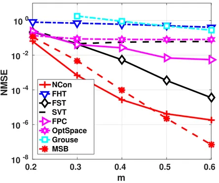
UE has a single (but not limited to) antenna. UEs are assumed to be close to one another (clustered UEs). . . 42 Figure 2.7 – Wireless backhaul scenario. . . 46 Figure 2.8 – Performance of normalized mean square error (NMSE) results with ECU,
MT =MR =32for all algorithms. . . 47 Figure 2.9 – NMSE results for ECU with MT =MR=64for all algorithms. . . 48 Figure 2.10–Performance of NMSE results with DDU,MT=MR=32form∈ [0.1; 0.7]. 48 Figure 2.11–Performance of NMSE results with DDU,MT=MR=64form∈ [0.1; 0.7]. 49
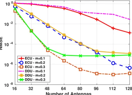
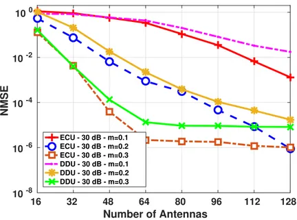
Figure 2.12–NMSE performance for different antennas number for m∈ {0.1, 0.2, 0.3}
for ECU and DDU with SNR equals30dB. . . 49
Figure 2.13–NMSE performance for different antennas number for m∈ {0.1, 0.2, 0.3}
for ECU and DDU with imperfect channel knowledge. . . 50 Figure 2.14–Performance MT =MR =32with ECU. . . 51 Figure 2.15–Performance MT =MR =32with DDU. . . 52 Figure 2.16–Performance for the channel recovery with ECU for UE with MR=100. . . 52 Figure 2.17–Performance for the channel recovery with the ECU, K=5, MR =10, and
Cl =2(rank=2). . . 53 Figure 2.18–Performance for the recovery with DDU and ECU using fast numerical soft
Figure 2.19–Performance for the MRT precoding with estimated channel error, 10 UE,
MR=1, andCl =10(rank=10). . . 54
Figure 2.20–Average BER performance for the channel recovery with ECU, K = 10, MR=1, andCl =10(rank=10). . . 55
Figure 2.21–Comparison for the goodput,10UE, MR=1, andCl =10(rank=10). . . 55
Figure 2.22–Average performance for the BER with estimated channel error, K =10, MR=1, andCl =10(rank=10). . . 56
Figure 3.2 – Performance of optimal solution (MILP), Lagrangean relaxation, ZFBF, MRT and three proposed heuristics with K=4,MT =64and χ=90%. . . . 76
Figure 3.3 – Average number of selected beams for K=4. . . 77
Figure 3.4 – Illustrative example for beams selection and power optimization using MILP, ZFBF and MRT. . . 78
Figure 3.5 – Comparative performance of mixed integer linear programming (MILP) and ZFBF with different sparsity levels for K=4and channel models. . . 79
Figure 3.6 – Performance of optimal solution (MILP), Lagrangean relaxation, ZFBF and MRT to K=4,MT=64and χ=90%. . . 80
Figure 3.7 – Performance of three proposed heuristics to K=4,MT =64with χ=90%. . 81
Figure 4.1 – System withLcells and a single UE. . . 86
Figure 4.2 – Example of transmission frame structure of a communication system. . . 87
Figure 4.3 – Comparison assuming low noise varianceσn2. . . 92
Figure 4.4 – Performance results for MT ∈ {32,64}. . . 92
Figure 4.5 – Performance with different numberMT. . . 93
LIST OF TABLES
Table 2.1 – Description of the Tx and Rx preamble. . . 39 Table 2.2 – Performance of NMSE results with ECU and DDU , MT = MR =32 and64
LIST OF ABBREVIATIONS AND ACRONYMS
3GPP 3rd Generation Partnership Project AGB antenna group beamforming AoA angle of arrival
AoD angle of departure
BDMA beam domain multiple access BER bit error rate
BILP binary integer linear programming BLER block error rate
BnB branch-and-bound BPSK binary phase shift keying BS base station
CS compressed sensing CSI channel state information D2D device-to-device
DDU direct data undersampling DFT discrete fourier transform
ECU estimated channel undersampling FDD frequency division duplexing
FHT fast numerical hard threshold algorithm FPC fixed point continuation
FST fast numerical soft threshold algorithm
Grouse grassman rank-one update subspace estimation i.i.d. independent identically distributed
ILP integer linear programming LA Lagrangean relaxation
LMUI limited multi-user interference LOS line-of-sight
LP linear programming LTE long-term evolution
LTE-A long-term evolution advanced MAC media access control
MC matrix completion
MMSE minimum mean square error MRT maximum ratio transmission MSB minimization split bregman MU multi-user
MUI multi-user interference NCon non-convex algorithm
NMSE normalized mean square error
OFDM orthogonal frequency division multiplexing OptSpace spectral matrix completion
p.d.f. probability density function QoS quality of service
RF radio frequency Rx receiver side
SDP semidefinite programming
SIC successive interference cancellation SINR signal-to-interference-plus-noise ratio SIR signal-to-interference ratio
SNR signal-to-noise ratio
ST-RPS space-time random pilot selection SVD singular value decomposition SVT singular value thresholding TDD time division duplexing Tx transmitter side
LIST OF SYMBOLS
ǫ Tolerance ν Number of bits
C Set of complex-value number N Normal distribution
R Set of real-value number
θ Angle of arrival ϑ Angle of departure
G Beam domain channel matrix L Number of cells
C Constant δ Data rate n Dimension α Fading amplitude µ Incoherency parameter ξ Wavelength
λ Lagrange multiplier
m Total number of the observed entries Cl Number of MU clusters
N Noise matrix S Symbol matrix σn2 Noise variance
ω1 Parameter of the algorithms ρ Transmit power
pr Probability r Rank
MR Number of receive antennas P Number of specular multipaths H Channel matrix
Y Received signal matrix τ Number of pilot sequences σa2 Angle variance
σ Singular value γ Minimum SINR
ds Inter-element antenna spacing χ Sparsity level
Tf Feedback data time
Tus Time required to begin the undersampling T Time required to read the preamble MT Number of transmit antennas Ω Set of the known entries PΩ Sampling operator Po Transmit power Q Target matrix X Matrix of variables
NT Number of transmit signal K Number of users
NOTATIONS
In this thesis the following conventions are used. Italic represents scalar quantities, boldface lower-case letters indicate vectors, and boldface upper-case letters express matrices.
Ri×j set of real-values numbers
(i×j)matrix dimensions
Ci×j set of complex-values numbers(i×j)matrix dimensions xi i-th vector element
|xi| modulus of i-th vector element
xT transpose of vectorx
xH Hermitian transpose of vector x x∗ conjugate of vectorx
kxk ℓ2norm of vectorx
Xi,j (i,j)-th matrix element
X−1 inverse of matrixX IN N×N identity matrix
1N “all ones” vector of dimensionsN
kXkp normpof matrixX
kXk2 spectral norm of matrixX
kXkF Frobenius norm of matrixX
kXk∗ nuclear norm of matrixX |hA,Bi| tr AHB
⊙ Hadamard product ⊗ Kronecker product h.i inner product
k.k∞ ℓ∞norm of a vector
v ec vectorization operator
diag the diagonal operator
O(.) bigOnotation
greater than or equal
E{.} the expectation operator
The collection of vectorsuk∈Rnfor1≤k≤d, denoteuikis thei-th vector element,
TABLE OF CONTENTS
1 INTRODUCTION . . . 21
1.1 Motivation . . . 22
1.2 Main Contributions . . . 24
1.3 Main Assumptions . . . 24
1.4 Thesis Organization . . . 24
1.5 Scientific Production . . . 26
1.5.1 Technical Reports . . . 26
1.5.2 Main Publications . . . 26
1.5.3 Related Publications . . . 27
1.5.4 How to Read This Thesis . . . 27
2 MATRIX COMPLETION AS A SOLUTION FOR A FEEDBACK CHAN-NEL PROBLEM IN MASSIVE MIMO SYSTEMS . . . 28
2.1 Motivation . . . 28
2.2 Objectives and Main Contributions . . . 29
2.2.1 Organization. . . 29
2.3 Proposed Framework to Channel Feedback and Reconstruction . . . 30
2.3.1 Background . . . 30
2.3.2 System Model . . . 31
2.3.3 Matrix Completion Technique . . . 32
2.3.4 Incoherence Property of Massive MIMO Channel . . . 35
2.3.5 General Problem . . . 36
2.3.6 Rx Description . . . 37
2.3.7 Operation Modes . . . 37
2.4 Application Scenarios . . . 40
2.4.1 Application Scenario 1: Wireless backhauling . . . 40
2.4.2 Application Scenario 2: MU . . . 41
2.5 Simulation Results . . . 43
2.5.1 Wireless Backhauling Scenario . . . 45
2.5.2 ECU Recovery with Perfect Channel Knowledge . . . 46
2.5.3 DDU Recovery with Perfect Channel Knowledge . . . 47
2.5.4 ECU and DDU Recovery with Imperfect Channel Knowledge . . . 50
2.5.5 MU Scenario . . . 52
2.6 Summary . . . 56
3 LOW-COMPLEXITY HEURISTICS TO BEAM SELECTION AND RATE ADAPTATION . . . 58
3.2 Main Contributions . . . 58
3.2.1 Organization. . . 59
3.3 Background . . . 59
3.4 System Model and Assumptions . . . 60
3.4.1 General Definitions . . . 60
3.4.2 Independent and Identically Distributed Beam Domain Channel Model . . 62
3.4.3 Geometric-Stochastic Beam Domain Channel Representation . . . 62
3.4.4 Beam Selection . . . 63
3.5 Problem Formulation . . . 65
3.6 Proposed Solution . . . 66
3.6.1 General Definitions . . . 66
3.6.2 Optimal Solution via Beam Selection, Power Beam Optimization and Rate Assignment: A MILP Formulation . . . 66
3.6.3 Lagrangean Relaxation via Dual Subgradient Optimization Algorithm . . 69
3.6.4 Low Complexity Heuristics . . . 72
3.6.5 Heuristic 1 – Minimum-Interference Greedy Assignment . . . 72
3.6.6 Heuristic 2 – Munkres-based Assignment . . . 73
3.6.7 Heuristic 3 – Minimum Interference Greedy Assignment with Munkres Initialization . . . 73
3.7 Simulations Results . . . 74
3.7.1 MCS with Extended Range . . . 78
3.7.2 Heuristics Robustness . . . 81
3.7.3 Complexity Analysis . . . 82
3.8 Summary . . . 83
4 MINIMIZATION OF PILOT CONTAMINATION EFFECT WITH SPACE-TIME PILOT TRANSMISSION SCHEME . . . 84
4.1 Motivation . . . 84
4.2 Main Contributions . . . 84
4.2.1 Organization. . . 84
4.3 Background . . . 85
4.4 System Model . . . 85
4.5 Proposed Solution: ST-RPS . . . 86
4.5.1 Interference Reduction with ST-RPS . . . 89
4.6 Simulation Results . . . 91
4.7 Conclusions and Future Works . . . 94
5 CONCLUSION . . . 95
5.1 Perspectives . . . 96
21
1 INTRODUCTION
T
his thesis is inspired by the problems in the recent technology termed5G or fifth-generation.In this introductory chapter, the main motivation and objectives of this thesis are presented in Sections 1.1 and 1.2, respectively. Section 1.3 describes the main assumption about the channel. Section 1.4 depicts the thesis organization, and, finally, publications are listed in Sections 1.5.2 and 1.5.3.
The world has seen four generations of mobile communications; the first (1G) in 1980s supported only voice; the second (2G) in 1990s added data transmission to voice; the third generation (3G) in 2001 extended the foundation of broadband data communication to support basic Internet services; the fourth generation (4G) in 2009 added the long-term evolution (LTE) system to achieve higher data rates paving the path for the future fifth generation (5G) of mobile communications which is the focus of our work.
The 5G is under development, promising higher data rates and even higher efficiency to mobile broadband communications [1]. However, the scope of5G is much broader than just
further an enhanced mobile broadband communication. Instead, 5G is commonly described as a platform that should enable wireless connectivity for mostly any kind of device or application as presented in Figure 1.1. These are vehicle-to-vehicle (connected cars), massive machine type, device-to-device (D2D), millimeter wave, long-term evolution advanced (LTE-A)/Wi-Fi inte-gration and micro-BS communications. Furthermore, the 5G is assumed to enable connectivity for a much more extensive range of new cases. For example, wireless connectivity for remote control of machinery, wireless connectivity for traffic safety and control, and monitor/control of infrastructure, virtual and augmented reality, tree dimension and ultra-high dimension video and haptic feedback applications, industrial automation and applications in health, such as re-mote surgery, smart cities, data from multiple domains (transportation, public administration, emergency services and weather sensing), and others [2].
The vast range of use cases in 5G means that the capabilities in this generation have to extend far beyond that previous ones. The 5G should support high peak data rates of10Gbits/s.
In urban and suburban environments, the forecast considers100Mbit/s, which means an increase
of factor 10 compared to what can be provided with current technologies. Another aspect is
the lower latency, where the order of 1ms is often mentioned. The extreme reliability is also
considered. It means very different things, for instance, an extremely low error rate (below10−9),
Chapter 1. Introduction 22
Figure 1.1 – Deployment scenario envisioned for 5G cellular system.
Source: Created by the author.
1.1 Motivation
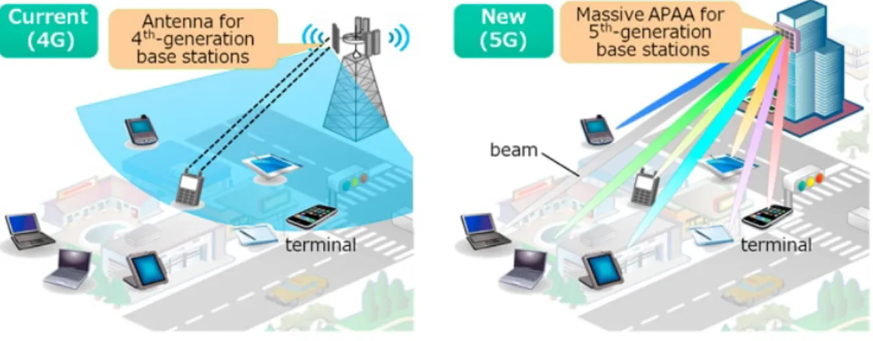
Consider the 4G and 5G networks showed in Figure 1.2. Note that the 4G system can serve one UE1with a broad beam, while the 5G network has narrow beams which can give support to more than one UE simultaneously These beams are provided by the increase on the number of antenna elements at the BS. Thereby, the BS with a large number of antennas is named as massive MIMO BS. It means a large number of antennas is generating narrow beams with potential to light UEs in distinct regions, configuring a MU massive MIMO scenario.
Figure 1.2 – Evolution of a 4G network into 5G Massive MIMO with active phased-array anten-nas (APAA) with massive antenna elements network.
Source: [3].
Massive MIMO is one of the key technologies for the 5G wireless communication
Chapter 1. Introduction 23
systems due to its potential to achieve high data rates and its robustness against interference, fading, hardware imperfections and failure [4]. In his seminal paper, Marzetta [5] showed that when the number of antennas grows very large, the effect of additive noise decreases, as well as the required transmitted energy per bit. The development of the new systems with massive MIMO can work in two operation modes, one based on time operation called time division duplexing (TDD) and another based on frequency operation called FDD. In TDD systems, the uplink and downlink transmissions are carried out using same frequency band, but separated in the time. Therefore, one can offer rely on channel reciprocity to acquire the CSI. However, the channel reciprocity may not hold, in practice, due to the calibration error between the uplink and downlink radio frequency (RF) chains [6, 7].
On the other hand, the uplink and downlink in the FDD systems utilize different frequencies. It is considered to be more effective under symmetric traffic and delay-sensitive applications due to small latency, continuous channel estimation, and backward compatibility. Moreover, the FDD operation mode is employed in most wireless systems of nowadays. However, FDD has a problem related with the channel feedback overhead that grows linearly with the number of BS (transmit) antennas [8]. Then, for practical feedback channels with limited transmission rate, the overhead to obtain the full CSI becomes prohibitively large due to the massive number of antenna elements. Thus, relying on CSI to design the downlink transmission emerges as a bottleneck in FDD systems. Furthermore, to fully utilize the spatial multiplexing and array gains expected for such promising technology, an accurate knowledge of CSI at the BS is essential to apply linear precoders as MRT or ZFBF.
Massive MIMO systems have potential to achieve high data rates mainly when more UEs are allocated the same frequency resource. Under this MU perspective, the systems have a huge potential to decrease the power consumption and to improve the communication system performance [9]. However, when the number of BS antennas is moderate, intra-cell interference among UEs appears and has to be effectively handled. Transmit beamforming is one of the techniques that achieves enhanced performance in MU massive MIMO systems, determining the complex antenna gains that optimize some performance criterion, e.g., the sum rate. The beamforming means that each data signal is sent from all antennas, but with different amplitude and phase to direct the signal spatially as shown in Figure 1.2 (right).
Chapter 1. Introduction 24
the same time/frequency resource than conventional systems which leads to more severe pilot contamination [10].
1.2 Main Contributions
This thesis deals with three key problems of 5G deployment, namely channel feed-back in FDD systems, beamforming design, and pilot contamination. The main contributions of the work can be summarized as follows:
• A general framework for reducing the feedback load in FDD systems using matrix completion;
• A precoder design based on the beam domain channel representation to deal with the intra-cell interference;
• A space-time random pilot selection scheme for minimizing the pilot contamination in a multi-cell scenario.
1.3 Main Assumptions
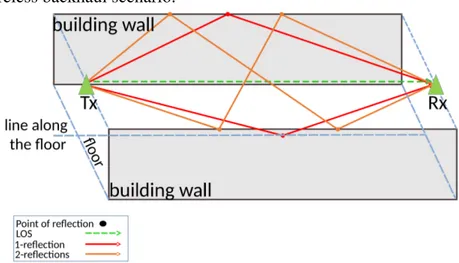
Many discussions about the wireless channel were raised over the last years. This thesis relies on the assumption of poor scattering channel, where the number of dominant multipaths is much smaller compared to the number of antennas. Finite scattering models are usually adopted for millimeter-wave (mmWave) scenarios [11]. For example, of 60 GHz with massive MIMO, the high path loss will lead the primary propagation paths to be only the line-of-sight (LOS) or the first and second order reflections [12, 13].
Other scenarios also present a low number of scatterers. For example, in a scenario where the BS is equipped with a large number of antennas located in an elevated position with few scatterers around (e.g., on the top of a high building, a dedicated tower, or a unmanned aerial vehicle platform), and mainly characterized by rich local scatterers around the UE (e.g., the classical one-ring model [14, 15]). Meanwhile, for arrays with small aperture, antennas are highly directive, further reducing the number of surrounding scatterers. Hence, the angular spread seen by the BS is quite small and the number of incoming signal paths is also limited.
Moreover, several related works assume similar insights [7, 16, 17, 18, 19, 20, 21, 22, 23, 24, 25, 26, 27]. Thereby, for the considered scenarios in this work, the channel matrix is assumed to have low-rank or at least have deficient rank.
1.4 Thesis Organization
Chapter 1. Introduction 25
Chapter 1presented an introduction about the next generation of mobile communi-cations considering the massive MIMO system and raised some problems related with this new technology.
Chapter 2 presents the use of MC technique to reduce the FDD uplink feedback channel overhead exploiting the low-rank structure in the channel matrix for its accurate re-construction from a few feedback information. In this context, a general framework which uses a matrix completion technique is proposed as a solution to the CSI feedback and recon-struction problem. The proposed framework is evaluated in two application scenarios: wireless backhauling communications and a clustered MU scenario uplink scenario.
Chapter 3describes a formulation of a precoder design that exploits the geometric sparsity of the MU massive MIMO channel considering a practical rate assignment based on the modulation and coding scheme (MCS) of the LTE table, beam selection, and power optimization. An optimal solution to capacity following the MRT principle is shown. A heuristic based on Lagrangean relaxation and three additional simple heuristics are presented.
Chapter 4 describes a scheme based on a space-time pilot transmission, named ST-RPS, to mitigate the destructive effect of pilot contamination. The space-time pilot method uses Bernoulli distribution to decide about the transmission. The obtained simulation results show that the scheme leads to improved channel estimation accuracy due the reduction of pilot contamination.
Chapter 5concludes this thesis by summarizing the main conclusions and listing some perspectives for future work.
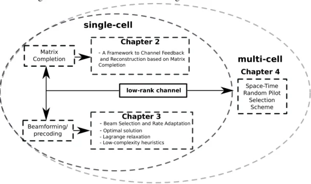
The organization of the thesis is illustrated in Figure 1.3.
Figure 1.3 – Organization of the thesis in a block-diagram.
Chapter 1. Introduction 26
1.5 Scientific Production
The publications produced during the thesis period are listed below. Those publi-cations may be divided into two general categories: main and related publipubli-cations. The main publications served as the basis for this thesis, while the related ones are about correlated topics.
1.5.1 Technical Reports
These are the reports that served as the basis for some problems addressed in this thesis. The first and third parts of this thesis which are related to Chapters 2 and 4, respectively, were developed under the context of Ericsson/UFC technical cooperation projects:
• UFC. 34:Transceiver Design in MIMO Communication Systems: Distributed Pro-cessing and Very-Large-Scale Approaches, February/2014 - August/2014;
• UFC. 41: Distributed Optimization and Very Large-MIMO Transceivers for 5G Wireless Communication Systems, October/2014 - May/2016,
in which a number of four technical reports, one in UFC.34 and three in UFC.41 were delivered:
• VALDUGA, S. T.; ALMEIDA, A. L. F. de.Fourth Technical Report UFC/Ericsson - Channel Estimation in Very-Large Scale MIMO. GTEL-UFC, July 2014; • VALDUGA, S. T.; ALMEIDA, A. L. F. de.First Technical Report UFC/Ericsson
-CSI Feedback and Reconstruction Using Matrix Completion for Massive MIMO Systems. GTEL-UFC, Mar. 2015;
• VALDUGA, S. T.; ALMEIDA, A. L. F. de.Second Technical Report UFC/Ericsson - Feedback Signaling and CSI Reconstruction Using Completion Techniques.
GTEL-UFC, Oct. 2015;
• VALDUGA, S. T.; ALMEIDA, A. L. F. de.Third Technical Report UFC/Ericsson - CSI Feedback and Reconstruction Using Matrix Completion and Tensor
Com-pletion for FDD Uplink Multi User Massive MIMO. GTEL-UFC, Feb. 2016. Also, a request for a patent application namedReduced feedback data using matrix completion for CSI acquisitionwas performed.
1.5.2 Main Publications
The following journal paper and a letter were produced:
Chapter 1. Introduction 27
• VALDUGA, S. T. et al. Minimization of Pilot Contamination Effect with Space-Time Pilot Transmission Scheme, 2018. To be submitted.
The second part of this thesis is related to Chapter 3 which includes a one-year internship at the I3S Laboratory, CNRS, France, under the context of the following I3S/UFC technical cooperation project:
• Massive MIMO Systems: Project and Modeling of the Large Scale MIMO Systems, February/2016 - February/2017.
As a result of this internship, a conference and a journal paper were produced:
• VALDUGA, S. T. et al. Low complexity beam selection for sparse massive MIMO systems. In: PROC. Int. Symp. Wireless Communication Systems (ISWCS). Italy: [s.n.], Aug. 2017. p. 414–419. DOI:10.1109/ISWCS.2017.8108150;
• VALDUGA, S. T. et al. Low-Complexity Heuristics to Beam Selection and Rate Adaptation in Sparse Massive MIMO Systems.Transactions on Emerging Telecom-munications Technologies - ETT, Feb. 2018. Submitted.
1.5.3 Related Publications
Some works were produced during the last years of this doctoral thesis, in the context of codebooks for MIMO systems:
• VALDUGA, S. T. et al. Low-Complexity Codebook-Based Beamforming with Four Transmit Antennas and Quantized Feedback Channel. In: 2014 IEEE Wireless Communications and Networking Conference (WCNC). [S.l.: s.n.], Apr. 2014. p. 1212–1217. DOI:10.1109/WCNC.2014.6952322;
• VALDUGA, S. T. et al. Esquema MIMO Beamforming Otimizado para Canal de Retorno de Baixa Taxa de Transmissão. In: XXXIII Simpósio Brasileiro de Telecomunicações, 2015, Juiz de Fora, Anais do XXXIII SBrT. [S.l.: s.n.], 2015. p. 1–5;
• VALDUGA, S. T. et al. Codebook Design and Performance Analysis of Quantized Beamforming under Perfect and Imperfect Channel State Information.Journal of Communication and Information Systems - JCIS, v. 32, n. 1, p. 161–171, 2017. DOI:10.14209/jcis.2017.16.
1.5.4 How to Read This Thesis
28
2 MATRIX COMPLETION AS A SOLUTION FOR A FEEDBACK CHANNEL PROB-LEM IN MASSIVE MIMO SYSTEMS
T
his chapter investigates the use of MC in order to reduce the FDD uplink feedback channel overhead, called here as the feedback channel problem. Our approach capitalizes on the low-rank structure of the MIMO channel.The MC technique is capable of recovering an unknown low-rank matrix, exactly or approximately, from undersampled observations, with or without noise [38, 39]. Under mild conditions, from the knowledge of a fraction of its entries (the matrix elements [40]) the desired matrix can be recovered by minimizing the nuclear norm (sum of singular values) of the observed matrix. According to the MC theory, only a few randomly chosen entries of the matrix are enough for the recovery of the whole matrix with good accuracy. In this context, there is a vast body of literature on MC theory and algorithmic solvers, as well as on more general matrix approximation problems such as theNetflixproblem [41] (see Figure 2.1), collaborative filtering, target estimation [42], sensor localization [43], machine learning [44], control [45], multi-linear algebra [46], and many others.
Figure 2.1 – Example of matrix completion problem in recommendation systems, e.g., given less than 1% of the movie ratings which the objective is to find missing ratings.
Source: [47]
2.1 Motivation
Chapter 2. Matrix Completion as a Solution for a Feedback Channel Problem in Massive MIMO Systems 29
compatibility. Moreover, in most wireless systems built today the FDD operation mode is gen-erally employed. Consequently, it is important to identify and develop solutions for potential issues arising on FDD-based massive MIMO technique.
2.2 Objectives and Main Contributions
Knowing that the feedback rate is one critical aspect in real-world wireless systems, the aim is to provide a solution to the problem of CSI acquisition at the BS with reduced load in the feedback channel of FDD-based massive MIMO systems. To the best of our knowledge, this work is the first to propose the use of MC in a general CSI feedback and reconstruction framework for massive MIMO systems. In the present work, upon reception of downlink pilots from the Tx, for example a macro BS, the receiver side (Rx), i.e., a micro-BS or a UE undersamples either the received pilot data matrix or the estimated channel matrix (depending on the chosen scheme), and feeds only a fraction of their entries back to the Tx. By capitalizing on MC, the Tx recovers the downlink pilots for subsequent channel estimation, or to directly reconstructs the downlink channel. Thereby, the transmitter is able to design simple linear precoders [48, 49] and beamformers that consider a full-channel knowledge. Our results show that, when the channel matrix has a low-rank structure, the proposed feedback and reconstruction schemes yield accurate CSI estimation with minimal feedback overhead, which translates into a high energy efficiency and low complexity at the Rx, a desired feature for power-limited uplink transmissions.
2.2.1 Organization
Chapter 2. Matrix Completion as a Solution for a Feedback Channel Problem in Massive MIMO Systems 30
2.3 Proposed Framework to Channel Feedback and Reconstruction
2.3.1 Background
In massive MIMO, the spatial focusing of energy into ever-smaller regions of space potentially brings huge improvements in throughput and radiated energy efficiency. Other benefits could also include the extensive use of inexpensive low-power components, low latency communication, simplification of the media access control (MAC) layer, and robustness to intentional jamming [4]. To fully utilize the benefits of such a promising technology, an accurate knowledge of the CSI at the BS is essential to apply linear precoders such as a simple MRT or a ZFBF. Henceforth, we focus on FDD operation. In this context, one well-known problem is that the channel feedback overhead grows linearly with the number of antennas [8, 50, 51, 52]. Then, for practical feedback channels with limited transmission rate, the overhead to obtain full CSI becomes prohibitively large due to the massive number of antenna elements. Thus, relying on CSI to design the downlink transmission emerges as a bottleneck in FDD systems. Furthermore, for practical feedback channels, the rate is limited and it is acceptable not to assume the transmission of full CSI to the BS. In this context, the availability of CSI at the transmitter to design the downlink transmission is a bottleneck in FDD systems. It is worth mentioning that in this thesis, we consider that the uplink feedback channel is error-free. Although this assumption may not hold in practice, good channel coding is usually applied to add robustness on the feedback channel against channel induced errors.
Solutions for reducing the amount of data to be sent via a limited feedback channel usually resort to compressed sensing (CS) techniques. These solutions consider that the channel matrices admit a sparse representation, for instance, because of the shared and limited local scattering. Therefore, due to the sparse channel structure, CS techniques can reduce the training sequence and feedback overheads [20, 53, 54, 55, 56]. In [20], a scheme to exploit the hidden joint sparse structure of channel matrices via CS was proposed. In [53], an adaptive CS-based feedback scheme was proposed, where the feedback structure can be dynamically configured based on channel conditions, while [54] presents and discusses the use of sparsity-inspired CSI acquisition techniques for massive MIMO, as well as the underlying mathematical theory in FDD and TDD modes. In [55], based on the spatial correlation and channel conditions, the authors suggested two compression methods for channel feedback to reduce the feedback overhead. A hybrid limited feedback design is proposed for massive MIMO in [56]. They consider quantized and codebook based feedbacks.
Chapter 2. Matrix Completion as a Solution for a Feedback Channel Problem in Massive MIMO Systems 31
missing elements. Comparing to CS techniques, the authors showed that MC technique can achieve a near-optimal spectral efficiency with significantly lower complexity, since it does not require basis as in CS, and it is immune to array response mismatch, as well.
Another solution is to exploit spatial correlation information. For instance, [58] proposes to design grouping patterns, taking advantage of the spatial correlation mapping of multiple antenna elements to a single representative value, using pre-designed patterns therein referred to as antenna group beamforming (AGB). However, full CSI is not available at the transmitter. Instead, the proposed scheme uses the pattern index to select the antenna group and the codeword index for transmit beamforming, making such a scheme limited. Another solution is presented in [59], which consists of a feedback scheme based on channel vector quantization and beamforming. The authors propose codebooks and UE selection for scheduling based on reliability information, channel quality indicator, channel direction indicator and rate approximation. However, this solution does not provide CSI to the transmitter.
The idea of applying a completion technique to MIMO communication appeared in [60] to obtain direction of arrival (DoA) for colocated MIMO radars. The solution consists of either performing a matched filtering with a small number of randomly selected dictionary waveforms or undersampling the received signal at random sampling instants and forward the results to a fusion center. From the received samples and the sampling scheme, the fusion center applies a MC technique to estimate the full matrix. In [25], the authors proposed a solution to provide the CSI to the Tx for FDD massive MIMO systems. The proposal is to apply an algorithm based on MC concepts. They consider that all scheduled UEs directly feed the full received pilots back to which they apply a low-rank approximation for CSI recovery. Therein, the authors formulate an optimization problem to the estimation of the channel under a low-rank constraint without undersampling. However, full CSI is conveyed back to the Tx, which can be a bandwidth consuming process. The approach of [61] estimates the channel matrix by means of a MC technique. The method is numerically investigated by considering different scattering environments for the MIMO channel model in an indoor scenario. Therein, the authors do not assume a low-rank channel model.
This work advances further than [54, 61] by presenting the problem in detail, while linking it to the massive MIMO paradigm. We also discuss two relevant application scenarios where the proposed approach is appealing.
2.3.2 System Model
Consider a wireless communication system, where a BS represents the Tx and the Rx can be represented by others BSs or the UEs. The Tx and Rx are equipped withMT andMR antennas, respectively.
During the downlink training phase, the BS sends pilot sequences of length NT to the Rx. The received signal at the Rx can be expressed as:
Chapter 2. Matrix Completion as a Solution for a Feedback Channel Problem in Massive MIMO Systems 32
whereH∈ CMR×MT is the channel matrix,S∈N
T×MT contains the pilot sequences, and N∈
CMR×NT the additive white Gaussian noise term.
The channel model is expressed as a sum of a finite (small) number of specular paths, as follows:
H= √1 P
P
Õ
p=1
αpar(θp)aTt(ϑp), (2.2)
wherePdefines the number of paths,αp is the fading amplitude associated with thep-th path, and the steering vector is defined as [62]:
ar(θp),
1, e−j2πdsξcos(θp), . . .,e−j2π (MR−1)ds
ξ cos(θp) T
, (2.3)
at(ϑp),
1, e−j2πdsξcos(ϑp), . . .,e−j2π (MT−1)ds
ξ cos(ϑp) T
, (2.4)
wheredsis the inter-element antenna spacing,ξis the wavelength, andθp,ϑp ∈ [0,π]are the angle of arrival (AoA) and angle of departure (AoD), respectively, associated with the p-th path. Furthermore, the channel model described in Equation (2.2) is a stochastic multipath channel [17].
2.3.3 Matrix Completion Technique
In this subsection, we discuss the low-rank matrix completion technique, following the nuclear norm minimization concept. The nuclear norm is alternatively known by several other names including the Schatten 1-norm, the Ky Fanr-norm, and the trace class norm. See [38, 63, 64] for a detailed discussion, full proofs and theoretical results of the exact and approximate recovery results to MC theory. The results developed in [63] extend the theory of CS to different structures, beyond the sparse structure. Furthermore, the MC theory benefits from the CS theory jointly with probability tools [65].
The problem can be defined as follows. There is a data matrixQ∈ Cn×nwhich we would like to know as precisely as possible. However, only some entries of this matrix are available and there is no way to find the unknown entries of it without imposing additional conditions. Thus, the problem is ill-posed. However, if the matrix has low-rank or has approxi-mately low-rank, then accurate or even exact recovery is possible by nuclear norm minimization [45, 63, 66]. In this case, one may accurately recover a low-rank matrix from relatively few measurements. Some results have shown that this is indeed possible [38, 39, 43, 64, 67].
More specifically, letQbe the desired matrix to be reconstructed. We assume that only a few entries ofQare known. For instance, if a tuple(i, j) ∈Ω, it means that the(i,j)-th entry ofQis known.
To undersampleQ, letPΩ:Cn×n→ Cn×ndenote the sampling operator defined by
PΩ(Q)=
Qi,j, if (i, j) ∈Ω
0, otherwise,
Chapter 2. Matrix Completion as a Solution for a Feedback Channel Problem in Massive MIMO Systems 33
whereQi,j is the(i,j)-th entry ofQ. The sampling operator simply undersamples its input matrix, setting the output matrix entries corresponding to the unknown elements ofQto zero.
For a great enough number of samples, sampling uniformly at random is expected to generate just a low-rank matrix with these samples. The classical problem of finding the best low-rank approximation to a given full matrixQis equivalent to solving the optimization problem:
ˆ
Q=arg min
X rank(X)
s.t.:PΩ(X)=PΩ(Q), (2.6) whereXis the matrix of variables andQˆ is a element-wise reconstruction ofQ[45, 68]. Notice that the constraint in Equation (2.6) makes sure that the entries of X corresponding to the known entries ofQare equal. However, in general, problem in Equation (2.6) is know to be a nondeterministic polynomial-time (NP) hard problem [69]. An alternative method to solve the problem using convex relaxation is proposed [45] as follows:
ˆ
Q=arg min
X kXk∗
s.t.:PΩ(X)=PΩ(Q). (2.7) More specifically, despite the fact that nuclear norm minimization was observed to produce very low-rank solutions in practice [45, 64, 66], theoretical results showed that it produces the minimum rank solution [63].
The nuclear norm is a convex function, and can be formulated using semidefinite programming (SDP). Thereby, given a general matrix Q, which may not be semidefinite or symmetric, the nuclear norm can be formulated in terms of SDP, by rewriting Equation (2.7) as follows:
ˆ
Q=arg min
X,Q1,Q2
tr(Q1)+tr(Q2)
s.t.:PΩ(X)=PΩ(Q), (2.8)
"
Q1 X XH Q2
# 0.
where the optimization variables areX,Q1andQ2. The optimization problem in Equation (2.8) and Equation (2.7) are convex. Thereby, they can be solved using general solvers available in the literature, e.g., [70].
In [67], Candès and Plan proved that if the entries of the matrix are corrupted by noise, it is possible to recover the whole matrix with a few samples. Let us assume a noisy model as follows:
Qi,j=Mi,j+Zi,j (i, j) ∈Ω, (2.9) whereZi,j with(i, j) ∈Ωcontains statistical or deterministic noise. Let us apply the sampling operator
Chapter 2. Matrix Completion as a Solution for a Feedback Channel Problem in Massive MIMO Systems 34
whereZ∈ Cn×n. The matrixMcan be recovered solving the following problem:
ˆ
M=arg min
X kXk∗
s.t.:kPΩ(X−Q)kF ≤ǫ. (2.11)
Assume that kPΩ(Z)kF ≤ǫ, whereǫ means a reconstruction error threshold. Further-more, when the noise is white and Gaussian with variance σ2n, thenǫ2≤ (m+√8m)σ2n with high probability [67], wheremis the undersampling factor. The precision of estimation depends on the structure of the targeted matrix. The singular values need to be sufficiently spread, or incoherent (Candès [63] and Recht [64]) for reconstructingQwith only a few samples. In MC theory [38, 63, 64, 67] the sampling is done uniformly at random, and some simple hypotheses about the matrixQwere developed, which make it recoverable. Let us describe these hypotheses briefly.
Consider the singular value decomposition (SVD) of the rank-PmatrixQ:
Q= P
Õ
i=1
σiuivHi . (2.12)
Consider the SVD ofQdescribed on Equation (2.12),PU andPV as the orthogonal projections onto the column and row space ofQrespectively (singular vectors):
PU= P
Õ
i=1
uiuHi , PV = P
Õ
i=1 viviH.
We define the matrixEas
E,Õ
i
uivHi , PUE=E=EPV, EHE=PV, EEH =PU.
To recover the matrix from part of entries, the vectorsuiandvineed to be “incoherent” (µ) in some sense.
More specifically, the assumptions are as follows:
Assumption 1.There existsµ1>0such that for all pairs(a,a′) ∈n×nand (b,b′) ∈ n×n,
|hea,PUea′i − P
n1
1a=a′| ≤ µ1 √
P
n , (2.13)
|heb,PVeb′i − P
n2
1b=b′| ≤ µ1 √
P
n , (2.14)
where id=sam]eis a canonical vector and1Ethe indicator function of an event E, e.g.1a=a′ is
equal 1 ifa=a′and0ifa,a′.|hA,Bi|is defined astr AHB.
Assumption 2.There existsµ2>0such that for all(a,b) ∈n×n
|Eab| ≤µ2
√
P
Chapter 2. Matrix Completion as a Solution for a Feedback Channel Problem in Massive MIMO Systems 35
If both assumptions hold, we say that the matrixQobeys the strong incoherence property with parameter µ=max(µ1,µ2).
Based on these hypotheses, [38] proposes the following theorem:
Theorem 1 LetQ∈ Cn×nbe a fixed matrix of rank-robeying the strong incoherence property with parameter µ. Suppose we observe m entries of Q with locations sampled uniformly at random. Then, there is a positive numerical constantCsuch that if
m≥Cµ2nrlog10̺ n, (2.16)
where ̺is an integer positive number, then Q is the unique solution to Equation (2.7) with probability at least1−n−3, i.e., with high probability, nuclear norm minimization recovers all the entries ofQwithout error.
2.3.4 Incoherence Property of Massive MIMO Channel
Following [38], the assumptions 1 and 2 ofHwhenr= P=1, can be measured by the singular vector. Comparing Equation (2.2) with the SVD ofH=ÍPi=1σiuiviH, theu1=ar(θ) andv1=at(ϑ)are the singular vectors. Thus, all entries ofPU have the same modulus1/MR and those ofPV have the same modulus1/MT . Whena=a′andb=b′,
hea,PUea′i=[PU]a,a′ =
1 MR , (2.17)
hea,PUea′i − 1
MR
=0, (2.18)
heb,PVeb′i=[PV]b,b′= 1
MT
, (2.19)
heb,PVeb′i − 1
MT
=0. (2.20)
Whena,a′andb,b′,
|hea,PUea′i|=|[PU]a,a|=
1
MR
, (2.21)
|heb,PVeb′i|= |[PV]b,b|=
1
MT. (2.22)
Thus, the incoherence property for assumption 1 and 2 withµ=1is satisfied.
Forr=P≥2, and a sufficiently large number of antennas, the singular vectors of the channel H converge to the steering vectors [57](see [71] for a detailed proof.). Thereby, all entries of the left and right singular vectors have the same modulus 1/√MR and 1/√MT, respectively. Hence,a=a′andb=b′
hea,PUea′i=[PU]a,a= P MR
, (2.23)
heb,PVeb′i=[PU]b,b= P MT
Chapter 2. Matrix Completion as a Solution for a Feedback Channel Problem in Massive MIMO Systems 36
and, fora,a′andb,b′,
|hea,PUea′i|=[PU]a,a′= P Õ
i=1
ui,au∗i,a′ (2.25) ≤ P Õ
i=1
|ui,a||u∗i,a′|=
P MR
, (2.26)
|heb,PVeb′i|=[PV]b,b′= P Õ
i=1 vi,bvi∗,b′
(2.27) ≤ P Õ
i=1
|vi,b||vi∗,b′|=
P MT
. (2.28)
Thus, equalityµ=√Psatisfies the incoherence property for assumptions 1 and 2 when MT,MR are very large. This means that whenHis large, it obeys the strong incoherence property with µ≈√P, and can be recovered with a small number of samples.
2.3.5 General Problem
In this section, we are interested in solving a general feedback problem.
To illustrate this problem, consider a conventional feedback scheme in a MIMO system, where the full channel matrix is conveyed from the Rx back to the Tx. The number of bits to be fed back is given by ν=κlog2(MRMT), where κdepends on the accuracy of channel information at the Rx. Assuming MT =MR =100and κ=3, the Rx needsν=39.8631bits to convey the full CSI to the Tx.
In this context, we resort to MC techniques to solve the feedback overhead problem, by exploiting the low-rank nature of the MIMO channel. The framework of the underlying idea is shown in Figure 2.2. The process is initialized with the Tx sending a forward data to Rx and,
Figure 2.2 – Framework structure.
Forward data Feedback data CSI Undersampling Pre-processing Post- processing
Tx
Rx
Q Completion ^ QSource: Created by the author.
Chapter 2. Matrix Completion as a Solution for a Feedback Channel Problem in Massive MIMO Systems 37
to obtain the CSI is based on pilot symbols, the forward data is a training sequence and the pre-processing block is the channel estimator. The parameter mis introduced to describe the undersampling factor related to the reduced feedback data. This factor is defined as a percentage of entries in the matrixQ(e.g.,m=0.1means that 10% of total entries were sent).
After receiving forward data sent by Tx, Rx may first pre-process such forward data. The result is the matrixQ. Then, Rx undersamplesQand the undersampled data are sent through the feedback channel. Tx receives the data and then applies MC to this matrix. At the end of this step, the matrixQis in turn reconstructed asQ. Finally, after a post-processing (channelˆ estimation), the CSI is made available at Tx.
Basically, there exist an informationa prioriat Tx needed to enable the application of MC. For instance, Tx must know the number of antennas at Rx and the rank of the channel matrix, which in general, are available at the BS [72]. Additionally, in particular applications some information may not be mandatory but beneficial, such as the undersampling factor, which is defined as the percentage of the entries ofYto be fed back, the data feedback mode, if multiple modes are pre-defined, and the data distribution, which can dictate the way the undersampling procedure is performed.
2.3.6 Rx Description
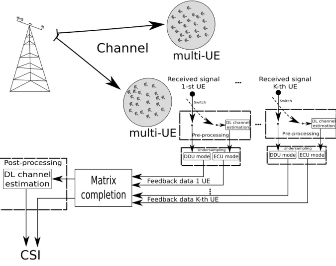
Although the framework is described for a single Rx, it can be extended to the case with multiple receivers, sayK Rxs. For instance, in a wireless backhaul scenario, there might exist K micro-BSs as Rxs. As a second example, there might exist K UEs in a MU scenario, since each one may have different goals. Thus, the framework may be applied individually. On the other hand, the Tx along with multiple receivers may have the same goal. In this case, every Rx would perform equally as they were a single Rx, being the Tx responsible for aggregating the individual feedback data from the Rxs. As a third case, the Tx can make different subsets of Rxs to send back different types of feedback data. Note that, regarding thea prioriinformation at Tx, it must apply for each link Tx-Rx and it is Rx-specific. That is, Tx has to know the number of antennas at each Rx, as well as the rank of each channel matrix.
2.3.7 Operation Modes
Herein, two types of feedback data are visualized: (a) the received signal matrixY, or (b) the estimated channel matrixH. Based on this, we define two operation modes:ˆ
• DDU: in this mode, a fraction of the received signalYis the feedback data, which means that Q=Y. Therefore, there is no pre-processing step. Consequently, Rx operates as a simple sampling device. Tx applies the completion algorithm to re-construct Y. Due to the noise, the matrix Y is actually full-rank. Eventually, Tx obtains a filtered version ofY, from which the channel matrixHˆ is estimated as a
Chapter 2. Matrix Completion as a Solution for a Feedback Channel Problem in Massive MIMO Systems 38
• ECU: in this mode, a fraction of the estimated channel Hˆ is the feedback data,
which means thatQ=H. Therefore, the pre-processing is a channel estimation stepˆ performed by the Rx taking into account the received signalY. At Tx side, there is no post-processing step.
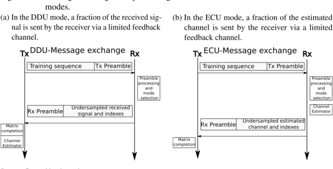
The main steps of the systematic message exchange between Tx and Rx are illustrated in Figure 2.3 for the DDU and ECU operating modes, respectively, and are summarized below:
• Tx sends the training sequence to Rx with a Tx preamble;
• Rx reads the Tx preamble. Then, Rx selects the mode and the undersampling factor. The extracted samples and index set are fed back to Tx along the with Rx preamble;
• Tx reads the Rx preamble. Then, Tx recovers the full data by using a MC algorithm.
Figure 2.3 – Message exchange and processing between Tx and Rx for the DDU and ECU modes.
(a) In the DDU mode, a fraction of the received sig-nal is sent by the receiver via a limited feedback channel.
Training sequence Tx Preamble
Tx Rx
Rx Preamble Undersampled received signal and indexes
Preamble processing
and mode selection
Matrix completion
Channel Estimator
DDU-Message exchange
(b) In the ECU mode, a fraction of the estimated channel is sent by the receiver via a limited feedback channel.
Training sequence Tx Preamble
Tx Rx
Rx Preamble Undersampled estimated channel and indexes
Preamble processing
and mode selection
Matrix completion
ECU-Message exchange
Channel Estimator
Source: Created by the author.
Basically, the preambles contain information about the pre-defined mode selection and undersampling factor, as described in Table 2.1. In Tx preamble a sequence of bits A = [A1, A2, A3] is used to choose between the DDU and ECU modes. A third mode, namely, full mode, is also covered, which coincides with the standard feedback scheme. The Rx preamble contains a sequence of bits B = [B1, B2, B3] to inform Tx what mode is in use. The bits A1 and B1 are reserved for extra modes and possible future implementations.
Chapter 2. Matrix Completion as a Solution for a Feedback Channel Problem in Massive MIMO Systems 39
in the DDU mode the Rx does not need to wait the reception of the entire incoming signal. On the other hand, in the ECU mode, the feedback data is the estimated channel. Thus, the Rx needs to wait the reception of the entire incoming signal to estimate the channel. Therefore, TDDU ≥TECU.
Table 2.1 – Description of the Tx and Rx preamble.
Bits Downlink Bits Uplink
A1 A2 A3 Tx preamble B1 B2 B3 Rx preamble
0 0 Full Mode - Defines that either DDU, ECU or full-CSI feedback (baseline) can be chosen, Rx selects the mode of operation.
0 0 Full Mode - Rx selects whether undersampling is used or not.
0 1 DDU mode - Direct data undersam-pling, Tusis the time required for
trig-gering the undersampling operation, i.e. the minimum value of T corre-sponds to the time required to read the preamble that defines the mode of op-eration.
0 1 DDU mode - Direct data undersampling.
1 0 ECU mode - Estimated channel under-sampling.
1 0 ECU mode - Estimated channel undersampling.
Source: Created by the author.
Figure 2.4 – Difference between DDU and ECU at the time.
Feedback
Data
Feedback
Data
Data
Tf
Training Data
Feedback
Training Data
Feedback
Chapter 2. Matrix Completion as a Solution for a Feedback Channel Problem in Massive MIMO Systems 40
Remark 1 The DDU mode has low computational complexity, low latency, and low energy consumption compared to the ECU mode, since it does not estimate the channel. If a full-duplex capability is available, that is more likely to be beneficial in the wireless backhaul scenario [2], Rx can feedback data to Tx while it is still receiving the signalY. Thus, Tx can obtain CSI more quickly and possibly use the time resources more efficiently by transmitting more data in the same data transmission interval, as illustrated in Figure 2.4. Besides, the computational burden associated with channel estimation is moved to the Tx side, which means that Rx saves energy as it does not need to estimate the channelH. On the other hand, according to Equation(2.1), Y contains an additive white noise term, which turns it a full-rank matrix. Even after a low-rank approximation within the matrix completion procedure, the reconstructed matrixYˆ is still corrupted by the additive noise in the DDU mode, which is adverse for channel estimation. In other words, while the ECU estimates the channel directly fromYand reconstructsH, whichˆ is already a low-rank matrix, DDU makes use of low-rank approximations ofYto estimate the channel from a corrupted version ofY.
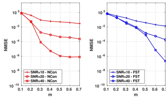
Remark 2 The advantages and disadvantages of the two data feedback modes imply a tradeoff between DDU and ECU. It would be interesting to have a criterion to switch between modes whenever one is more advantageous than the other. For example, in a scenario of very high signal-to-noise ratio (SNR), DDU is no longer affected by noise and it would perform close to ECU (the simulation results confirm this claim). If the NMSE gap between both schemes is tolerable DDU might be preferable due to the considerable energy saving compared to ECU.
In what follows, we illustrate the framework with two application examples: wireless backhauling and a clustered MU scenario.
2.4 Application Scenarios
In this section, we apply the proposed framework in two relevant scenarios. The first is a new problem imposed in massive MIMO systems with heterogeneous networks supporting a macro-cell layer with additional small cells, where wireless backhauling communications take place between the macro-BS and a micro-BS. The second one is related to MU channel estimation in a clustered MU massive MIMO system.
2.4.1 Application Scenario 1: Wireless backhauling
In dense cell deployments, wired backhaul becomes expensive or even infeasible due to the large number of network nodes to be connected. As an alternative to overcome this limitation, millimeter-wave wireless backhaul, e.g., in60GHz, can be adopted [73, 74, 75].