UNIVERSIDADE DO ALGARVE
A Correlation Aware Algorithm for Energy Efficiency Improvement in FiWi
Networks
Shirin Sabzivand Dezfool
Master Thesis in Informatics Engineering
Work done under the supervision of:UNIVERSIDADE DO ALGARVE
A Correlation Aware Algorithm for Energy Efficiency
Improvement in FiWi Networks
Shirin Sabzivand Dezfool
Master Thesis in Informatics Engineering
Work done under the supervision of: Prof. Doutor No´elia Correia
N E T W O R K I N G
Work done at Research Center of Electronics Optoelectronics and Telecommunications (CEOT).
Acknowledgements
I would like to express special thanks to my advisor, Professor Doctor No´elia Correia, for her guidance and support. This work could not have been done without her dedication, suggestions, encouragement and remarkable guidance during the elaboration of this dissertation.
I am also grateful to Professor Doctor ´Alvaro Barradas for all his attentions, ideas and suggestions.
I also address my special thanks to my friends Sergio Sabino and Amin Mohtasham. The discussions I had with them during this work were of great help.
I would like to extend my sincerest thanks to my family, specially my parents, Gholamhos-sein and Shohreh, and my husband Hassan for their support.
Abstract
Energy saving is an important issue that should be taken into consideration when planning telecommunication networks. In FiWi access networks the potential for energy consumption reduction is higher, compared to other architectures. The reason is that different routes toward the optical section can be used by routers at the wireless section. This dissertation focuses on an approach for energy saving in FiWi access networks that uses the variations of packet flows at ONUs as a basis of decision to put ONUs to long sleep. Cross-correlation is used to measure the similarity between the time series containing packet flow information at ONUs, which may reveal that traffic sources are near each other. This happens, for example, when nodes are in each other transmission range, and doing TDM, or when equal-cost multi-path is used by routers for QoS increase. If such similarity is detected one of the ONUs can go to sleep since an alternative ONU can be reached. In this work an approach is proposed which uses cross-correlation function to find the similarity between traffic flows at ONUs. A discrete event simulation model has been developed by using OMNeT++ framework to evaluate the performance of the proposed approach. The simulation results show that the proposed approach is able to detect the similarity, and identify the correlated ONUs, therefore being useful for easy sourcing purposes.
Keywords: Fiber-Wireless Access Network, Wireless Mesh Network, Energy Saving, Cross-Correlation, Quality of Service, Network Simulation.
Resumo
Na altura de se planear uma rede de telecomunicac¸˜oes um dos aspectos mais importantes ´e a eficiˆencia energ´etica da rede. Nas redes de acesso FiWi o potencial de reduc¸˜ao do consumo energ´etico ´e maior quando comparado com outras arquitecturas. A raz˜ao deste aumento de po-tencial ´e que existem v´arios caminhos que podem ligar um utilizador na sec¸˜ao sem fios `a sec¸˜ao ´optica. Esta dissertac¸˜ao debruc¸a-se sobre uma abordagem para poupanc¸a de energia em redes de acesso FiWi que utiliza como base de decis˜ao, para colocar ONUs em modo de hibernac¸˜ao prolongada (long sleep), as variac¸˜oes do fluxo de pacotes nas ONUs. ´E utilizada correlac¸˜ao cruzada para medir a similaridade entre series temporais, com informac¸˜ao do fluxo de pacotes ao longo do tempo, que poder´a indicar a existencia de fontes de tr´afego perto umas das outras. Isto acontece quando n´os est˜ao na ´area de transmiss˜ao uns dos outros, e a fazer TDM, ou quando os n´os est˜ao a utilizar m´ultiplos caminhos de igual custo (equal-cost multi-path) para aumentar a qualidade de servic¸o. Se for detectada similaridade entre ONUs ent˜ao uma das ONUs poder´a ser colocada em modo de hibernac¸˜ao prolongada dado que ´e poss´ıvel alcanc¸ar uma ONU alter-nativa. Neste trabalho ´e proposta uma abordagem que utiliza a func¸˜ao de correlac¸˜ao cruzada para detectar similaridade nos fluxos das ONUs. ´E desenvolvido um modelo de simulac¸˜ao de eventos discretos na framework OMNeT++ para avaliar o desempenho da abordagem proposta. Os resultados das simulac¸˜oes mostram que a abordagem proposta permite detectar similari-dades, tornando-se poss´ıvel a identificac¸˜ao de ONUs correlacionadas, podendo esta informac¸˜ao ser usada para poupar energia.
Palavras chave: Redes de acesso fiber-wireless, redes sem fios em malha, poupanc¸a en-erg´etica, correlac¸˜ao cruzada, qualidade de servic¸o, simulac¸˜ao de redes.
Contents
Statement of Originality ii Acknowledgements v Abstract vi Resumo vii Nomenclature xiii 1 Introduction 11.1 Motivation and Scope . . . 1
1.2 Objectives . . . 2
1.3 Contributions . . . 2
1.4 Thesis Outline . . . 2
2 FiWi Networks 4 2.1 Wireless Access Networks . . . 5
2.2 Optical Access Networks . . . 7
2.3 Enabling Technology . . . 8
2.3.1 FSO . . . 8
2.3.2 RoF . . . 9
2.3.3 R&F . . . 9
2.4 Available FiWi Architectures . . . 9
2.4.1 Architecture Based on EPON and WiMAX Access Networks . . . 9
2.4.2 FiWi Architectures Based on WiFi Technology . . . 12
3 Energy Saving Approaches 18
3.1 Energy Efficiency . . . 18
3.2 Problem Definition . . . 20
3.3 State of the Art . . . 20
3.4 Summary . . . 21
4 Proposed Energy Saving Approach 22 4.1 Cross-Correlation . . . 22
4.2 Correlation in Internet Traffic . . . 25
4.3 The Use of Cross-Correlation for Energy Saving in FiWi Networks . . . 26
4.3.1 Detecting Similarity Between Traffic Flows . . . 28
4.3.2 Summary . . . 30 5 Simulation Model 32 5.1 Network Simulator . . . 33 5.1.1 OLT . . . 33 5.1.2 WRouter . . . 36 5.1.3 WGrouter . . . 37 5.1.4 ClientNode . . . 38
5.1.5 Proposed Approach to Use the Result of the Cross-Correlation Ap-proach to Save Energy . . . 38
5.1.6 Summary . . . 39
6 Simulation Result 40 6.1 Performance Analysis . . . 40
6.1.1 Time Division Subregion A: . . . 42
6.1.2 Time Division Subregion B: . . . 43
7 Conclusions and Future Work 46 7.1 Conclusion . . . 46
List of Figures
2.1 Fiber wireless access network. . . 5
2.2 Wireless mesh networks: a) infrastructure; b) client; c) hybrid [4]. . . 6
2.3 Architectures for the integration of EPON and WiMAX [8]. . . 10
2.4 Multistage integrated broadband access network [8]. . . 12
2.5 Optical unidirectional fiber ring interconnecting WiFi based wireless access point [4]. . . 13
2.6 Two-level bidirectional path-protected ring (BPR) architecture [4]. . . 14
2.7 Optical hybrid star-ring network integrated with WiFi-based wireless access point [4]. . . 15
2.8 Optical unidirectional WDM ring interconnecting using WMN multiple PONs integrated with a WiFi-based wireless mesh network [4]. . . 16
2.9 A Radio and Fiber architecture [5]. . . 17
3.1 OLT-initiated sleep mode signaling [10]. . . 19
4.1 cross-correlation between vector i and j. . . 23
4.2 cross-correlation between vector d and e. . . 24
4.3 cross-correlation between vector n and m. . . 25
4.4 Time division in wireless front-end. . . 30
5.1 Simulated network. . . 33
5.2 (a) OLT and its component, (b) OLT’s NED code. . . 34
5.3 Queue model in detail. . . 35
5.4 Queue’s NED code. . . 36
5.5 WRouter and its components. . . 37
5.6 WGrouter and its component ONU. . . 37
5.7 ClientNode and its component app. . . 38
List of Tables
6.1 Constant parameters adopted in simulations. . . 41 6.2 Results For the Cross-Correlation Detection in Subregion A. . . 43 6.3 Results For the Cross-Correlation Detection in Subregion B. . . 45
Nomenclature
Abbreviations
10G-EPON : 10 Gigabit EPON
4G : Fourth Generation
ATM : Asynchronous Transfer Mode
AOP : Active Optical Network
AP : Access Point
BK : Backoff
BPON : Broadband Passive Optical Network
BS : Base Station
CO : Central Office
CTS : Clear to Send
CW : Contention Window
DCF : Distributed Coordination Function DSL : Digital Subscriber Line
EPON : Ethernet PON
FiWi : Fiber-Wireless
FSO : Free space optical
FTTH : Fiber To The Home
FTTX : Fiber To The Premises
GPON : Gigabit PON
IEEE : Institute of Electrical and Electronics Engineers
IP : Internet Protocol
LOS : Line-of-Sight
MAC : Media Access Control
MANET : Mobile Ad hoc Network
OLT : Optical Line Terminal
ONU : Optical Network Unit
PCF : Point Coordination Function
PHY : Physical
PON : Passive Optical Network
QoS : Quality of Service
RAU : Remote Antenna Unit
RE : Reach Extender
RF : Radio Frequency
R&F : Radio and Fiber
RoF : Radio over Fiber
STA : Subscriber Station
TDMA : Time Division Multiple Access TDMA-PON : Time Division Multiple Access PON
TFR : Traffic Flow Rule
WDM : Wavelength Division Multiplexing WDM-PON : Wavelength Division Multiplexing PON
WiFi : Wireless Fidelity
WiMAX : Worldwide Interoperability for Microwave Access WLAN : Wireless Local Area Network
WMN : Wireless Mesh Network
Variables
Si : Time seri representing the traffic of ONU i.
µi : The mean of Si. i : The variance of Si.
ij : Cross covariance between two time series Siand Sj.
⇢ij : Cross-Correlation Coefficients
T : Predefined time window.
K : Number of time series needed to store traffic of a single ONU in the time window T . L : Length of time series.
: Threshold.
Mij : Maximum of absolute values of cross-correlations among different lags.
C : Cross-Correlation Matrix. cij : components ofC.
C H A P T E R
1
Introduction
1.1 Motivation and Scope
Besides global warming, the continuously increasing cost of energy has strongly contributed for energy-efficient communication networks to become a point of attraction for researchers. Fur-thermore, operators and customers would like to use more environment friendly technologies. One of the most effective ways of decreasing energy consumption in communication networks is to identify the periods of time in which there is a lack or reduction of traffic in order to make a turn off schedule (completely or partially) of devices [1]. These energy consumption methods are known as sleep mode techniques. The impact of such techniques is higher if used at devices that do not aggregate too much traffic, which is the case of devices more near the user. These devices also exist in large number reducing even more the global network energy expenditure [2].
Access networks are the largest part of communication networks. They are the ”last mile” of telecommunication networks connecting the central office (CO) to the end users and, therefore, usually contain a large number of active devices to serve users spread across an area. One of the architectures that has been recently proposed to meet the needs of current and future services is the hybrid fiber-wireless (FiWi). This architecture joins optical and wireless technologies to provide both high bandwidth and ubiquity. In this case the optical network units (ONUs) are the devices where there is more room for energy saving using sleep mode techniques [3]. One of the biggest challenges in using power saving mechanisms is to prevent the decrease in quality of service (QoS). The quality of user experience should remain unchanged while some devices are in sleep mode. Another challenge is to make decisions while avoiding heavy exchange of network state information. The main motivation for this work is to study FiWi access networks and analyze the impact of using a correlation-aware approach for energy saving in FiWi networks. This approach takes QoS into consideration while minimizing network state
1.2. OBJECTIVES information exchange.
1.2 Objectives
The objective of this work is to evaluate if correlation analysis at the optical section can be used to decide which ONUs should enter long sleep mode while ensuring good alternative routes. It includes the following tasks:
• Analysis of FiWi networks.
• Analysis of sleep mode techniques. • Proposal of a correlation aware aproach.
• Development of a simulation model to evaluate the proposed correlation approach. • Proposal of an approach to decide which ONUs should go to sleep mode and when this
should occur.
1.3 Contributions
The main contributions of this work are the following:
• Presentation of a state-of-art on FiWi access networks with focus on the energy saving problem.
• An approach that uses correlation between traffic flows at the ONUs as a basis for sleep mode assignment.
• A simulation model to evaluate the proposed correlation approach. • An approach to use the correlation result in energy saving favour.
1.4 Thesis Outline
This dissertation is organized as follow:
Chapter 1 presents an introduction to the subject, motivation and scope of the work. The objectives are mentioned in this chapter and the contributions are referred.
1.4. THESIS OUTLINE
Chapter 2 provides an overview of FiWi access networks, states the enabling technolo-gies, and the main architectures for enabling FiWi integration are described.
Chapter 3 introduces the energy saving approaches related to FiWi access networks, more specifically the ones that are related to the ONUs, and also presents a state-of-art on the energy efficiency problem.
In chapter 4 an energy efficiency approach is proposed. Mathematical formulation, the use of the proposed approach and the related state-of-art is also presented.
Chapter 5 presents the FiWi simulation model. The model components and their func-tionality are explained in this chapter.
In chapter 6 some scenarios are tested to analyse the proposed energy saving approach. A possible way to use the result of the simulation result is proposed.
C H A P T E R
2
FiWi Networks
One of the biggest challenges for Internet providers is to provide fast Internet that can be ac-cessed at any time, any place and with any device. There is a continuously increasing request for Internet access through different types of devices, in different types of places. So, network providers need to extent their network to cover more places. Wireless and optical technologies are of great help to achieve this goal. They can be used together to complement each other.
Optical fiber provides a large amount of bandwidth but the problem is that the places that it can reach are limited. Even though, it has been used in houses, between cities and even countries, still it is not reachable in some places. On the other hand, wireless access networks are more flexible in the places they can reach. The weak point of wireless networks is that the transmission channel noisy and the bandwidth is very limited.
Fiber-Wireless (FiWi) networks use both technologies to trade-off between accessibility and bandwidth. FiWi access networks consist of two parts, a end and a front-end. The back-end is an optical access network and the front-back-end is a multi-hop wireless mesh network where users connect to have access to the Internet. A widely used technology at the back-end is the optical passive network (PON), which includes one or more optical line terminals (OLTs) at the central office that are connected to many optical network units (ONUs) near the wireless section. The wireless section includes wireless gateway routers for connection to the ONUs at the optical back-end, as shown in Figure 2.1. At the front-end any radio technology can be used, i.e WiMAX or WiFi.
2.1. WIRELESS ACCESS NETWORKS
OLT
ONU1 ONU2 ONU3
Wireless Mesh Router Wireless Mesh Client Fiber Connection Wireless Connection Optical Back-End Wireless Front-End ONU4
Figure 2.1: Fiber wireless access network.
2.1 Wireless Access Networks
Recent advances in wireless communications technology have led to significant innovations that have enabled cost-effective and flexible wireless Internet access, and provided incentives for building efficient multihop wireless networks. A wireless ad hoc network precludes the use of a wired infrastructure and allows hosts to communicate either directly or indirectly over radio channels without requiring any prior deployment of network infrastructure. WiFi technologies such as IEEE 802.11 b/g and IEEE 802.11a standards and WiMAX IEEE 802.16 standards are generally deployed as the main technologies for the wireless part of the FiWi access networks [24]. In WiFi the MAC layer uses distributed coordination function (DCF) as the default tech-nique to access the transmission medium. In DCF the subscriber stations (STAs) associated with the AP use their radio interfaces to sense if a channel is available, and if it is available, the source STA sends its data to the destination through the associated AP [25]. Wireless mesh networks (WMNs), on the other hand, are networks employing multihop communications to
2.1. WIRELESS ACCESS NETWORKS
activities for corporate and personal benefit, but also helps reduce fuel consumption and protect the environment, issues that are becoming increasingly important in our lives [3].
In this article we provide an up-to-date sur-vey of FiWi access networks. After reviewing state-of-the-art wireless and optical access net-works and briefly highlighting future develop-ments in both areas, we focus on enabling technologies and elaborate on emerging FiWi architectures, and also discuss their future chal-lenges. The remainder of the article is structured as follows. The next two sections overview the state of the art of wireless and optical (wired) access networks, respectively. We then describe enabling technologies and various FiWi network architectures. In the following section we address future challenges of emerging FiWi networks. The final section concludes the article.
WIRELESS ACCESSNETWORKS:
STATE OF THEART WIRELESSMESHNETWORKS
Recent advances in wireless communications technology have led to significant innovations that have enabled cost-effective and flexible wireless Internet access, and provided incentives for building efficient multihop wireless networks. A wireless ad hoc network precludes the use of a wired infrastructure and allows hosts to commu-nicate either directly or indirectly over radio channels without requiring any prior deployment of network infrastructure.
Wireless mesh networks (WMNs), on the other hand, are networks employing multihop communications to forward traffic en route to and from wired Internet entry points [4]. In con-trast to conventional WLANs and mobile ad hoc networks (MANETs), WMNs promise greater flexibility, increased reliability, and improved performance. WMNs can be catego-rized into infrastructure, client, and hybrid WMNs (Fig. 1). A router in an infrastructure WMN has no mobility and performs more func-tions than a normal wireless router. Among oth-ers, a router performs mesh functions (routing and configuration) and acts as a gateway. In a
client WMN, clients perform mesh and gateway functions themselves. Efficient routing protocols provide paths through the wireless mesh and react to dynamic changes in the topology, so mesh nodes can communicate with each other even if they are not in direct wireless range. Intermediate nodes on the path forward packets to the final destination. Due to the similarities between WMNs and MANETs, WMNs can apply ad hoc routing protocols (e.g., ad hoc on-demand distance vector [AODV] and dynamic source routing [DSR], among others).
ENABLINGTECHNOLOGIES
New technologies and protocols in the physical (PHY) layer, medium access control (MAC) pro-tocols, and routing protocols are required to optimize the performance of WMNs. In the PHY layer, smart antenna, multi-input multi-output (MIMO), ultra wideband (UWB), and multi-channel interface systems are being explored to enhance network capacity and further enable wireless gigabit transmission. Recently, gigabit transmission resulting from a combination of MIMO and orthogonal frequency-division multi-plexing (OFDM) has been demonstrated. MAC protocols based on distributed time-division mul-tiple access (TDMA) and CDMA are expected to improve the bandwidth efficiency of carrier sense multiple access with collision avoidance (CSMA/CA) protocols [4].
Currently, IEEE 802.11 a/b/g (WiFi) tech-nologies are widely exploited in commercial products and academic research of WMNs due to their low cost, technological maturity, and high product penetration [5]. However, since these protocols were originally designed for WLANs, they clearly are not optimized for WMNs. Proprietary wireless technologies and WiMAX have been proposed. Unlike WiFi, IEEE 802.16 allows for point-to-multipoint wireless connections with a transmission rate of 75 Mb/s and can be used for longer dis-tances.
Additionally, orthogonal frequency-divisiom multiple access (OFDMA) and smart antenna technologies extend the scalability of WiMAX. These technologies are exploited to enhance the capacity, reliability, and mobility of WMNs. !
!
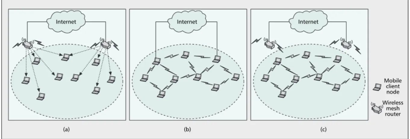
Figure 1. Wireless mesh networks: a) infrastructure; b) client; c) hybrid.
(a) Internet (b) Internet (c) Internet Mobile client node Wireless mesh router
MAIER LAYOUT 1/19/09 2:45 PM Page 161
Figure 2.2: Wireless mesh networks: a) infrastructure; b) client; c) hybrid [4].
forward traffic along a wireless route to/from wired Internet entry points [4].
WMNs consist of mesh routers and mesh clients, where mesh routers have minimal mobility and form the backbone of WMNs. The integration of WMNs with other networks such as the Internet, cellular, IEEE 802.11, IEEE 802.15, IEEE 802.16, sensor networks, etc., can be accomplished through a gateway and bridging functions in the mesh routers. Mesh clients can be either stationary or mobile, and can form a client mesh network among themselves and with mesh routers. WMNs are anticipated to resolve the limitations and to significantly improve the performance of ad hoc networks, wireless local area networks (WLANs), wireless personal area networks (WPANs), and wireless metropolitan area networks (WMANs). They are undergoing rapid progress and inspiring numerous deployments. WMNs will deliver wireless services for a large variety of applications in personal, local, campus, and metropolitan areas [23].
WMNs can be categorized into infrastructure, client, and hybrid WMNs, see Figure 2.2. A router in an infrastructure WMN has no mobility and performs more functions than a normal wireless router. Among others, a router performs mesh functions (routing and configuration) and acts as a gateway. In a client WMN, clients perform mesh and gateway functions them-selves. Efficient routing protocols provide paths through the wireless mesh and react to dynamic changes in the topology, so mesh nodes can communicate with each other even if they are not in direct wireless range. Intermediate nodes on the path forward packets to the final destination. Due to the similarities between WMNs and mobile ad hoc networks (MANETs), WMNs can apply ad hoc routing protocols (e.g., ad hoc on demand distance vector [AODV] and dynamic source routing [DSR], among others) [4].
New technologies and protocols in the physical (PHY) layer, medium access control (MAC) protocols, and routing protocols are required to optimize the performance of WMNs. In the
2.2. OPTICAL ACCESS NETWORKS
PHY layer, smart antenna, multi-input multi-output (MIMO), ultra wideband (UWB), and mul-tichannel interface systems are being explored to enhance network capacity and further enable wireless gigabit transmission. Recently, gigabit transmission resulting from a combination of MIMO and orthogonal frequency-division multiplexing (OFDM) has been demonstrated. MAC protocols based on distributed time-division multiple access (TDMA) and CDMA are expected to improve the bandwidth efficiency of carrier sense multiple access with collision avoidance (CSMA/CA) protocols [4, 23].
2.2 Optical Access Networks
Optical fiber provides incomparable bandwidth potential compare to the wireless and any other known transmission medium. A single strand of fiber offers a total bandwidth of 25, 000 GHz. Optical networks are able to offloading electronic equipment by means of optical bypassing as well as reducing their complexity, footprint, and power consumption significantly while pro-viding optical transparency against modulation format, bit rate, and protocol. Among different architectures that can be deployed for fiber access networks [26], PONs are widely deployed as FTTX access networks.
Typically, PONs are time-division multiplexing (TDM) single-channel systems, where the fiber infrastructure carries a single upstream wavelength channel (from subscribers to a cen-tral office) and a single downstream wavelength channel (from a cencen-tral office to subscribers). IEEE 802.3ah Ethernet PON (EPON) with a symmetric line rate of 1.25 Gb/s, and International Telecommunication Union Telecommunication Standardization Sector (ITU-T) G.984 Gigabit PON (GPON) with an upstream line rate of 1.244 Gb/s and a downstream line rate of 2.488 Gb/s represent current state-of-the art commercially available and widely deployed TDM PON access networks, but standardization efforts have already been initiated in the IEEE 802.3av Task Force to specify 10 Gb/s EPON. GPON offers strong operation, administration, mainte-nance, and provisioning (OAMP) capabilities, and provides security at the protocol level for downstream traffic by means of encryption using advanced encryption standards. Furthermore, GPON efficiently supports traffic mixes consisting not only of asynchronous transfer mode (ATM) cells but also TDM (voice) and variable-size packets by using the GPON encapsulation method (GEM). Adding the wavelength dimension to conventional TDM PONs leads to WDM PONs [4].
In TDM PONs, there are two wavelength channels, one for sending traffic from the ONUs to the OLT, referred as upstream, and one for sending traffic from the OLT to the ONUs,
re-2.3. ENABLING TECHNOLOGY
ferred as downstream. In the upstream, ONUs must declare for bandwidth by exchanging re-quest/response messages with the OLT. Since this is a multipoint to point network, usually time division multiple access (TDMA) techniques are used. WDMA techniques can be used to in-crease network capacity and scalability. In TDMA-PON systems, the bandwidth is shared in time domain, where each ONU has its specific time slot to transmit data packets. OLT synchro-nizes transmission time slots and sends the informations to the ONUs to let them know when to send packets. In the downstream, traffic is broadcast to all the ONUs and an ONU ignores any traffic not intended to it [3]. In this chapter, we provide information about current technologies that allow us to construct FiWi networks and available architectures enabling FiWi integration.
2.3 Enabling Technology
Here we describe three different technologies used to implement FiWi networks [4, 5]: 1) Free space optical (FSO), also known as optical wireless (OW).
2) Radio over fiber (RoF). 3) Radio and Fiber (R&F).
In the next three subsections, we will discuss these technologies.
2.3.1 FSO
FSO is a line-of-sight (LOS) technology approach. It uses invisible beams of lights to provide optical bandwidth connection. It is capable to send up to 25 Gbps of data including simultaneous voice and video communications1. This type of optical connection does not require neither
expensive fiber-optic cable nor securing spectrum licenses for radio frequency (RF) solutions. FSO technology is based on connectivity between FSO-based optical wireless units, each consisting of an optical transceiver with a transmitter and a receiver to provide full-duplex ca-pability. Each optical wireless units uses an optical source and a lens or telescope that transmits light through the atmosphere to another lens receiving the information. FSO can provide point-to-point or point-to-multipoints connection with high data rate. It can be implemented on both ring or star architectures, but the best architecture to maximize the availability is to use the meshed architecture that includes both ring and star architectures.
2.4. AVAILABLE FIWI ARCHITECTURES
2.3.2 RoF
Radio-over-Fiber is another technology that enables us to have the benefits of optical fiber and wireless. RoF allows an analogue optical link to transmit a modulate radio frequency signal [4]. RoF network supports many digital formats and wireless standards (e.g WCDMA,WLAN,GSM).
In this technology wireless signals go from the CO to the remote antenna units in an optical form. Each RAU communicates over a radio link with one or more user mobile stations within the radio range of its base station2.
RoF networks can establish point-to-point or point-to-multipoint connections. A full-duplex RoF system providing 2.5Gb/s data transmission up to 50Km, with less than 2dB power atten-uation, was successfully demonstrated using the millimetre wave band [4].
2.3.3 R&F
Radio-and-Fiber is another technology for the integration of optical and wireless networks. In R&F two different MAC protocols are used, so a translation must be done at the interface of optical and wireless segments by an suitable optical-wireless device, such as optical network unit-base station (ONU-BS) [7, 22], which means that the traffic generated from wireless users (wireless MAC frames) is not moving directly along the optical fiber to be processed at the CO by the OLT. As a result, the negative impact of the propagation delay of the fiber on the MAC protocol (e.g. timeout triggers) will decrease and the performance of the network will increase. This feature removes the possible limitation regarding the optical fiber range which WLAN-based RoF networks have [7, 6, 21].
2.4 Available FiWi Architectures
In this section we present some FiWi network architectures based on different technologies.
2.4.1 Architecture Based on EPON and WiMAX Access Networks
There are many ways to integrate EPON and WiMAX access networks. Here we mention some of them.
2.4. AVAILABLE FIWI ARCHITECTURES Independent Architecture
In this approach, a WiMAX base station can be considered as a generic user that is directly connected to an EPON ONU (Figure 2.3). This independent architecture is very simple. There is no need for special requirements at the interconnection between the two system boxes as long as they support a common standard interface (e.g. Ethernet) and operate independently of each other [8].
Figure 2.3: Architectures for the integration of EPON and WiMAX [8].
Hybrid Architecture
This architecture integrates an ONU and WiMax-BS into a single system, which is called ONU-BS [8].
Because the integrated ONU-BS has the full information on bandwidth request and allo-cation and packet scheduling of both ONU and WiMAX BS, it is possible to employ efficient mechanisms for bandwidth requests in the upstream direction of the EPON system, and band-width allocation and packet scheduling in the downstream direction of the WiMAX system. More specifically, because the ONU-BS has the full information on how WiMAX subscriber stations (SS) request bandwidth from the BS, the ONU-BS can make a better prediction on the bandwidth requirement in the next cycle in the EPON and thus send a more accurate bandwidth request to the OLT. Since the ONU-BS has the full knowledge on the bandwidth that has been
2.4. AVAILABLE FIWI ARCHITECTURES
requested from the EPON for the next cycle of transmission, the WiMAX BS can make an op-timal bandwidth allocation and packet scheduling for SSs in the subsequent WiMAX frames. Thus, compared to the previous independent architecture, the hybrid architecture is expected to achieve better performance in terms of throughput and service QoS. As a disadvantage, the hy-brid architecture is not standardized. Also, a fully-capable ONU-BS may not be cost-effective for situations that require an ONU or a WiMAX BS only.
Unified-Connection-Oriented Architecture
This approach takes into consideration the fact that the overall operational principles of WiMax and EPON, in the perspective of allocation and bandwidth request, are entirely similar. This means that we can have a common bandwidth request and allocation protocol for both of them in an integrated way. More specifically, the unified-connection-oriented architecture is similar to hybrid architecture but here the WiMax control protocol is run in the PON section [8]. Since it is a type of Fixed Mobile Convergence (FMC) in network control and management, it is expected to make operation very simple and have a good performance and QoS support. Microwave-Over-Fiber Architecture
In the previously discussed architectures, both wireless and wired data are transmitted in the fiber baseband but in Microwave-Over-Fiber (MOF) the EPON signal is transmitting on the fiber baseband and the WiMAX signals are transmitted on the optical subcarrier. The WiMAX signal is modulated on a wireless carrier frequency, and is then multiplexed and modulated together with the baseband EPON signal onto a common optical frequency (wavelength) at the ONU-BS. The central node consists of a conventional EPON optical line terminal (OLT) and a central WiMAX BS, called a macro-BS. The OLT processes the baseband EPON signal, while the macro-BS processes data packets originating from multiple WiMAX BS units [4, 8]. Multistage EPON and WiMax Networks
As proposed in[8], besides the above architectures, by using next generation EPON techniques (e.g.10GEPON) and mesh networking of WiMax, we can develop an advanced multi-stage EPON and WiMax integrated system. The covering of huge broadband service area, better network capacity utilization, flexible type of network’s design and operation and support the handover operation across macro-cells, could be mentioned as the advantages of this architec-ture shown in Figure 2.4.
2.4. AVAILABLE FIWI ARCHITECTURES
Figure 2.4: Multistage integrated broadband access network [8].
2.4.2 FiWi Architectures Based on WiFi Technology
Optical Unidirectional Fiber Ring Interconnecting WiFi Based Wireless Access Point In this architecture, as proposed in [4, 9], the CO is connected to multiple WiFi-based wireless access points (WAPs) with an optical unidirectional fiber ring that runs throughout a service area. The CO manages the transmission of data between mobile client nodes (MCNs) and their related WAPs, also acting as a gateway to other networks, see Figure 2.5.
This architecture supports multi-hop relaying, where the two ends of a wireless link are connected via several intermediate relaying mobiles that help to extend the transmission range [4, 9] and help to extend the transmission range. Path diversity is also supported in this ap-proach, where the CO sends information to two different WAPs, which makes the first/last mile of the communication link with mobiles users more reliable.
2.4. AVAILABLE FIWI ARCHITECTURES
Figure 2.5: Optical unidirectional fiber ring interconnecting WiFi based wireless access point [4].
Two-level Bidirectional Path-Protected Ring (BPR) Architecture
In this architecture the CO interconnects Remote Nodes (RNs) through a dual fiber ring [4]. Each RN is connected to many wireless access point throw Concentration Nodes (CN), where each WAP offers services to the MCNs. Each RN has a protection unit and a bidirectional wavelength add-drop multiplexer based on a multilayer dielectric interference filter [27], see Figure 2.6.
The WAP comprises an optical transceiver, a protection unit, up/down RF converters. Each WAP provides channel bandwidth of at least 5 MHz and covers up to 16 MCNs by means of frequency division multiplexing (FDM). Under normal operating conditions, the CO transmits downstream signals in the counter-clockwise direction via RNs and CNs to the WAPs. If a fiber cut occurs between two RNs or between two CNs, their associated controllers detect the failure by monitoring the received optical signal and then switch to the clockwise protection ring. If a failure happens at a WAP, the signals are switched to other optical paths using an optical switch inside the affected WAP. This architecture provides high reliability, flexibility, capacity, and self-healing properties [4].
2.4. AVAILABLE FIWI ARCHITECTURES
Figure 2.6: Two-level bidirectional path-protected ring (BPR) architecture [4].
Optical Hybrid Star-Ring Network
This architecture is a combination of optical star and ring networks. Each fiber ring accommo-dates several WiFi-based WAPs, optical switches connect fiber rings to neighbor fiber rings and to the CO, see Figure 2.7. On traffic demand changing, lightpaths are dynamically reconfigured.
2.4. AVAILABLE FIWI ARCHITECTURES
Figure 2.7: Optical hybrid star-ring network integrated with WiFi-based wireless access point [4].
Optical Unidirectional WDM Ring Interconnecting Using WMN
This architecture consists of an optical WDM backhaul ring with multiple single-channel or multi-channel PONs attached to it. The OLT of each PON connects to the WDM ring by means of an optical add-drop multiplexer (OADM). Wireless gateways are used to bridge PONs and WMNs, see Figure 2.8.
Cost effectiveness bandwidth efficiency, wide coverage, high flexibility and scalability are the advantages of this architecture.
2.4. AVAILABLE FIWI ARCHITECTURES
Figure 2.8: Optical unidirectional WDM ring interconnecting using WMN multiple PONs integrated with a WiFi-based wireless mesh network [4].
In this thesis it is considered a R&F based FiWi access networks. At the optical part a PON technology such as EPON or GPON, in a tree topology with one OLT is assumed. At the wireless part a WMN generally composed by IEEE 802.11 and IEEE 802.16 standards is assumed. Figure 2.9 shows the University of California (UC) Davis R&F testbed integration of two EPONs and an IEEE 802.11g WLAN-based WMN with a maximum transmission rate of 54 Mb/s for voice, video, and data traffic, similar to the one adopted in this thesis.
2.5. SUMMARY
Figure 2.9: A Radio and Fiber architecture [5].
2.5 Summary
This chapter includes an introduction to FiWi access networks . It presents an overview about optical and wireless access networks. Three technologies Rof, R&F and FSO that are used to implement the FiWi networks are presented. Then some available architecture for enabling FiWi integration and their pros and cons are presented. This thesis will assume a R&F based FiWi access networks with a mesh front-end in the following chapters.
C H A P T E R
3
Energy Saving Approaches
3.1 Energy Efficiency
In the context of FiWi access networks, there will be a significant reduction in energy con-sumption if power saving techniques are used at the ONUs. This is so because, in comparison to other PON devices, the number of ONUs is higher and they aggregate less traffic. Also, in PON access networks the downstream traffic is broadcast to all ONUs, which discard traffic not destined to them, meaning that there is unproductive use of energy. This could be avoided if ONUs switch to sleep mode when there is no traffic to send or receive [10]. Any traffic destined to a sleeping ONU (upstream or downstream) needs to be buffered.
In general, ONU power consumption solutions can be classified into [11]: i) ONU power shedding,
ii) ONU dozing, iii) ONU deep sleep,
iv) ONU fast sleep.
The power shedding technique shuts down unused ONU parts, which may be inactive or are non-essential. This technique keeps the optical link fully operational which means that the transmitter and receiver are always active [11]. In the dozing technique the ONU ignores its upstream allocations as long as it has no traffic to send, although the downstream link stays fully operational [11, 12]. In deep sleep technique most ONU functionalities and transceiver remain completely off for the whole duration of the sleep state. The ONU can wake up when the user switches it on or when a local timer expires. This solution reaches maximum power saving [11, 12]. In the fast sleep mode technique the ONU goes through a sequence of sleep and
3.1. ENERGY EFFICIENCY
active periods. During a sleep period the ONU behaves like deep sleep mode, so it is completely powered off and just some timing and detection functionalities remain active. During an active period the ONU works normally. The OLT controls the transitions between these two periods. The ONU goes to sleep mode when it receives a sleeping message from the OLT and wakes up when its timer expires. There is a synchronization state after the ONU has woken up and before going completely to normal operation. The downstream traffic destined to a sleeping ONU is buffered at the OLT and can be delivered as soon as it wakes up [12]. Many new sleep mode scheduling technique have been illustrated to improve the sleeping mechanism and they can be classified in one of the above techniques. In Figure 3.1 a diagram is used to clarify the sleeping and waking up methods.
Figure 3.1: OLT-initiated sleep mode signaling [10].
The optimal length of a sleep period depends on the traffic load, the desired energy saving and the QoS requirements. If scheduling of sleep periods is considered valuable even when the QoS requirements are quite stringent, then short sleep periods are preferable. The QoS re-quirements are met if the sleep state duration does not exceed the maximum tolerable additional queuing delay due to the presence of the sleep mode technique. But the length of sleep periods has a lower bound. This is set by the wake-up time required by the ONU transceiver to return to the active state. In fact, in order to have a benefit in terms of energy conservation, the sleep
3.2. PROBLEM DEFINITION
period must be longer than the wake-up time. On the other hand, if energy saving is the primary objective and QoS impairments are not so stringent, long sleep periods should be scheduled. These long periods worsen delay and jitter performances, thus the QoS requirements set an upper bound for the duration of the sleep state. In conclusion, the length of the sleep period should be determined as a result of the trade-off between QoS requirements and desired energy conservation [12, 28].
3.2 Problem Definition
According to what has been previously stated about FiWi architectures, ONUs can be identified as the devices where a reduction in energy consumption would have a great effect on energy expenditure. Therefore, if some ONUs could be put to long sleep mode, while keeping QoS acceptable, more energy could be saved. Another possibility, besides using the sleep mode techniques previously discussed, is to explore the fact that in FiWi networks any gateway con-nected to an ONU can be used by wireless nodes for traffic forwarding to the Internet. That is, multiple routes exists from wireless node to the optical section. Under these circumstances the routing protocols end up finding alternative routes for wireless traffic delivery toward the Internet. This energy saving (ES) problem, which is the focus of this thesis, can basically be defined as follow:
Definition 3.1 (FiWi-ES Problem): Given a FiWi access network find the ONUs that should go to sleep mode, while ensuring routes from wireless nodes to ONUs with some Quality of Service (QoS).
3.3 State of the Art
Many approaches have been proposed to enter ONUs into sleep mode. The basis of decision for ONUs to go to sleep mode is the level of activity at the network. In [13] a MAC that uses fixed time slots for bandwidth allocation to ONUs is proposed. This is to be applied under light load conditions. The OLT is responsible for monitoring traffic load and when the load is lower than a defined threshold, system enters power saving mode. Within a chosen slot, each ONU wakes up periodically and do its transmission. Outside the slot, the ONU can go back to sleep and just keep user side receiving buffer awake. In [14] when an ONU is lightly loaded and because the OLT can not always determine the next wake up time, a minimum sleep window is assigned
3.4. SUMMARY
to the ONU by the OLT. After expiration of sleep window, the ONU listens to the traffic from the OLT and if there is no traffic the ONU continues in sleep mode. The sleep window grows (double the previous sleep interval) and keeps growing while no traffic arrives to the ONU. In [15], to enable power saving mode, two downstream scheduling algorithms were analyzsed and they propose a scheme to match downstream transmission with upstream slots. In [16] they propose a hybrid mechanism to provide effective power-saving performance according to frame inter-arrival time.
In this work we propose a different approach to enter ONUs to long sleep mode and, there-fore save energy. The approach is based on the correlation analysis at the optical section to decide which ONUs should enter long sleep mode while ensuring good alternative routes.
3.4 Summary
This chapter focuses on energy saving approaches, more specifically at ONU. Four power con-sumption solutions to be applied at the ONUs are presented. At the end, the state of the art about approaches to put ONUs into sleep mode is presented.
C H A P T E R
4
Proposed Energy Saving Approach
In this chapter first we explain the mathematical concept of cross-correlation. This concept is to be used by the approach proposed to solve the energy saving problem. Some examples have been provided to clarify the concept. In the second section, some related work about correlation in Internet traffic will be mentioned. In the third section, we will explain our work using the adopted cross-correlation formula for energy saving purposes.
4.1 Cross-Correlation
Cross-correlation is a statistical measure that is generally used to measure the similarity (having the same pattern) between two time series, called correlation. The range of the cross-correlation result is between -1 and 1. If the cross-cross-correlation is equal to 1, we can say there is a high positive similarity between the two time series, if it is equal to -1, it means we have a high negative similarity. Zero means there is no correlation between time series. One of the features of the cross-correlation is that it can detect similarity even if the time series have been shifted. In the following paragraphs, the mathematical description of cross-correlation is provided. Let Si = {Si(t)} be a stationary time series. This stationary time series has constant mean
µi = E[Si(t)]and constant variance i = E[(Si(t) µi)2]. The cross covariance between two
time series Siand Sj at lag k is defined as follows, see [17]:
ij(k) = E[(Si(t) µi)(Sj(t + k) µj)], k = 0, 1, ... (4.1)
Since ij(k) = ji( k)we define cross covariance function for Si and Sj to be ij(k) for
4.1. CROSS-CORRELATION
Definition 4.1 (cross-correlation coefficient) The dimensionless quantity ⇢ij(k) = ij
(k)
i j
k = 0,±1, ±2, ±3, ... (4.2)
is called cross-correlation between two series Si and Sj at lag k , which is a number between
-1 and 1 [17].
Here, some examples are provided to clarify the concept of the cross-correlation. The Matlab software has been used to plot the results.
Example 4.1 Let i and j be two similar time series with length = 20,
i =
1 3 5 6 4 8 10 7 5 3 2 9 8 11 10 3 4 6 7 8
j =
1 3 5 6 4 8 10 7 5 3 2 9 8 11 10 3 4 6 7 8
As shown in figure 4.1, the value of the cross-correlation is equal to 1 at Lag 0. It complies with the fact that two time series are identical with no shift.
4.1. CROSS-CORRELATION
Example 4.2 Now, consider two identical time series where one them is shifted four times with respect to the other one.
d =
1 3 5 6 4 8 10 7 5 3 2 9 8 11 10 3 4 6 7 8
e =
4 6 7 8 1 3 5 6 4 8 10 7 5 3 2 9 8 11 10 3
Figure 4.2 shows that the value of the cross-correlation is almost equal to 1 at lag 4 which means that the two time series are identical with four units of delay.
Figure 4.2: cross-correlation between vector d and e.
Example 4.3 Let n and m be the following two time series which have no similarities
n =
4.2. CORRELATION IN INTERNET TRAFFIC m =
21 9 5 12 4 80 25 7 51 3 17 90 81 6 19 5 41 36 1 9
Figure 4.3: cross-correlation between vector n and m.
Figure 4.3 shows that the value of cross-correlation is close to zero in all lags. This confirms the fact that there is no similarty betwen two time series m and n.
In order to apply this tool on real data, one needs to set a threshold for the value of the cross-correlation. Two times series having a cross-correlation value above the threshold are considered correlated and the one having a cross-correlation value below the threshold are con-sidered not correlated. The value of the threshold depends on the amount of the data and noises. Our simulations and some previous works done by others1 suggests a threshold of 0.7. If the
data is very noisy, the value 0.5 can be set as a threshold also.
4.2 Correlation in Internet Traffic
Many approaches have been proposed to measure and quantify the correlation between flows in different connections in order to understand, classify and model traffic in the network. In particular, it has been shown that for wide and local-area networks the self similarity (autocor-relation) between traffic flows applies. The correlation between different connections of a wide
4.3. THE USE OF CROSS-CORRELATION FOR ENERGY SAVING IN FIWI NETWORKS
area network which is the French scientific network ”Rentar” is analyzed in [18]. and Random matrix theory (RMT) is used to study the corresponding empirical correlation matrix.
The problem of traffic classification using very few supervised training samples is investigated in [19]. A novel non-parametric approach, traffic classification using correlation (TCC), was proposed to investigate correlation information in real traffic data and incorporate it into traffic classification.
In [20], correlation is used for network security purposes. It is analysed how flow correla-tion helps the adversary to identify the path of the flow and consequently reveal other critical information related to the flow.
As just discussed, correlation in Internet traffic has been used in different ways and in different types of networks. In this work, correlation is used to find the similarity between traffic flows in wireless front-end in FiWi networks. The information extracted from this approach can help us to put some ONUs into long sleep mode which will lead to an increase of energy saving in FiWi networks.
4.3 The Use of Cross-Correlation for Energy Saving in FiWi
Networks
In this section first we describe how the cross-correlation function is to be used to find the correlated ONUs, what does it reveal and how can we use the results of this function to save energy. That is, the approach to find the similarity between traffic flows at the ONUs is presented and then an approach to decide which ONUs, those with correlation, should enter long sleep is discussed. The ONUs to enter long sleep should ensure the existence of an alternative ONU to which wireless nodes can send their traffic, with no significant change in QoS.
In FiWi networks, each ONU sends its traffic to the OLT (upstream) that can keep track of the number of packets and queue sizes of each ONU. The measurement of the amount of packets at uniform time intervals can be used to generate sequences of data points (time series). By analyzing these time series, having delay into consideration, we can extract information about routes/ONUs being used by traffic sources.
The traffic of each ONU i = 1, . . . , n, in a predefined time window T , is stored in K = T L
finite time series Sk
i ={Sik(l)}Ll=1where L is the length of each time series and K is the number
of time slots. The component Sk
i(l)denotes the number of packages received by ONU i at time
(l + kL) where k runs from 0 to (K 1). The mean value and variance of the time series Sk i
are denoted by µk
4.3. THE USE OF CROSS-CORRELATION FOR ENERGY SAVING IN FIWI NETWORKS
and j we will compute the cross correlations ⇢kk0
ij between time series Sikand Sk
0 j . ⇢kkij0 = kk0 ij k i k 0 j k, k0 = 0, . . . , (K 1), (4.3) where k,k0 ij = E[(Sik(l) µki)(Sk 0 j (l) µk 0 j )]. (4.4)
We will use maximum of the absolute of the cross correlations among different lags i.e.
Mij = max
k,k0=0,..,(K 1)|⇢
k,k0
ij |, (4.5)
to detect correlation between ONUs i and j. A threshold is fixed to determine accep-tance/rejection, i.e.
Mij ) time series are correlated
Mij < ) time series are not correlated
For a FiWi network with n ONUs, we will record the correlation information between ONUs in the (n ⇥ n) symmetric matrix C = [cij]where for different ONUs i and j
cij =
(
1 ,if Siand Sj are correlated
0 , otherwise , (4.6)
The proposed approach to detect correlation between ONUs is summarized in following pseudo-code.
4.3. THE USE OF CROSS-CORRELATION FOR ENERGY SAVING IN FIWI NETWORKS
Data: n finite time series Si, number of time slots K and threshold .
Result: n ⇥ n cross-correlation matrix C.
1 for each i = 1, ..., n do
2 divide time series Siin K equal length time series Sik k = 0, ..., K 1 3 end 4 for each i, j = 1, .., n do 5 if i = j then 6 Set cii = 0 7 end 8 if i 6= j then 9 for each k, k0 = 0, ..., K 1do 10 Calculate ⇢kkij0 defined at (4.3) 11 Set Mij = maxk,k0=0,..,(K 1)|⇢k,k 0 ij | 12 end 13 end 14 if Mij then 15 Set cij = 1 16 else 17 Set cij = 0 18 end 19 end
Algorithm 1: Cross-Correlation Function.
In Chapter 5, we will present results of simulations that have been done to calculate the matrixC in different scenarios. Then a proposal on how to use matrix C in order to save energy in FiWi networks is discussed.
4.3.1 Detecting Similarity Between Traffic Flows
In a WMN, high speed routers equipped with advanced antennas, communicate with each other in a multi-hop fashion over wireless channels and form a broadband backhaul [29]. When the nodes are in each other’s interference area they are able to communicate either through a single frequency channel, and time division must occur, or send traffic in parallel by using different channels. In a TDMA wireless section, several nodes time-share a common carrier
4.3. THE USE OF CROSS-CORRELATION FOR ENERGY SAVING IN FIWI NETWORKS
frequency to communicate with the base station (ONUs). TDMA is usually combined with fre-quency division multiple access (FDMA), as different carrier frequencies are used in different nodes. Frequencies are only reused in nodes sufficiently distant in order to minimize interfer-ence [31]. In this work we have just considered the upstream traffic and TDM in upstream direction. This traffic is usually routed using the shortest path. To be able to send traffic toward the optical section in parallel, multiple shortest paths can be considered. A technique named equal-cost-multipath (ECMP) makes this happen. The ECMP can be used to spread load across the network. By maximizing the spreading of load among equal-cost paths, the bandwidth of links can be used more efficiently since network congestion is minimized, improving QoS. The ECMP technique is supported by OSPF (Open Shortest Path First), RIP (Routing Information Protocol) and static routing [30]. When employing cross-correlation coefficient we expect to detect similarity in the following conditions:
Time Division: Whenever nodes are in the same interference area and use the same fre-quency channel, time division will be used. This means that when one ONU receives high traffic flow the other ONU will receive low traffic flow. As a result of using TDM this will keep happening throughout time. So we can use the cross-correlation approach to find the similarity between traffic flows toward the ONUs and expect a negative cross-correlation coefficient. We can say that when nodes are making TDM, in the absence of one of the ONUs, traffic can be rerouted and traffic nodes are able to exchange the traffic to the other ONU, this exchange is possible because the nodes are in the same interference area and are using the same frequency channel. In Figure 4.4 a simple TDM scenario is illustrated. Nodes are connected with one frequency (F1), so they are all in each other’s interference/transmission area and because of that they can not send traffic in parallel. In TDM having fixed-length time slots each node has a specific time to send its traffic. In the table the time slots where nodes can send traffic are set. Equal demand and traffic load is being considered for all the nodes. Node 2 sends its traffic toward ONU1 through node1. In the absence of ONU1 node2 could reroute traffic and send it to the ONU2 through node3.
4.3. THE USE OF CROSS-CORRELATION FOR ENERGY SAVING IN FIWI NETWORKS 1 2 3 Gateway2 Gateway1 F1 F1 F1 F1 F1 F1 F1 F1 Tim eslot Clien t-node 1 2 3 F1 T0 T1 T2
Time division sequences between client nodes. Client-node Routes: 1 -> Gateway1 2-> 1 -> Gateway1 3 -> Gateway2
Node can send traffic Node can not
send traffic
Figure 4.4: Time division in wireless front-end.
ECMP: ECMP technique is helpful to detect the similarity when there is a common traffic source between ONUs. As we said before, when ECMP is used in a network multiple shortest path are used. Thus, when nodes are using multiple-channel communication and there is no time division, they can send traffic in parallel to different ONUs. This can lead to a noticeable simultaneous increase and decrease in traffic flow reaching to the ONUs. In this situation it is possible to say that similarity between traffic can be detected and a positive correlation is expected. It can be assumed that when we have ECMP and there is no time division, and high correlation detected between ONUs, there is/are node(s) in wireless section that has/have multiple routes to the optical part. Thus, if one of the ONUs becomes unavailable there is an alternative route to send the traffic toward the optical section.
In both the above cases, when a negative or positive correlation has been detected between ONUs, one of the ONUs can be put into the long sleep because there is an alternative route that nodes can use and by use of the new route send their traffic to the ONU. This way energy consumption can be decreased as some ONUs can be put into long sleep whenever the network becomes lightly loaded.
4.3.2 Summary
This chapter explains the mathematical concept of cross-correlation. Some examples and the related works is provided to clarify this concept. Some related work about correlation in Internet
4.3. THE USE OF CROSS-CORRELATION FOR ENERGY SAVING IN FIWI NETWORKS
traffic is presented. Finally, it is explained how to use the adopted cross-correlation formula for energy saving purposes is explained.
C H A P T E R
5
Simulation Model
In this chapter the simulation model used to test and evaluate the proposed approach is de-scribed. The model is created using the OMNeT++ simulation platform. OMNeT++ is a discrete-event simulation environment that supports the development of well organized component-based architectures whose components (modules) at the lowest level have to be programmed in C++. These modules are assembled into larger components. A model is contracted using a high-level language (NED). NED stands for Network Description. NED gives the user the abil-ity to declare simple modules, connect and assemble them into compound modules. The whole model, called ”network” in the OMNeT++ framework, is itself a compound module1. The
net-work topology used in this model is the one presented in Figure 5.1 with one OLT, three ONUs and gateways on the border between the optical and wireless sections, and nine wireless routers. The architecture of the model components is described in the following sections.
5.1. NETWORK SIMULATOR
clientNode[6]
clientNode[7]
Figure 5.1: Simulated network.
The organization of this chapter is as follow, Section 5.1.1 describes the OLT and its related sub-models: manager, queue, cross-correlation, and sink. In Section 5.1.2 the WRouter and its sub-models networkLayer and nic are presented. Section 5.1.3 includes, WgRouter with sub module onu. In Section 5.1.4, app submodule from clientNode is presented.
5.1 Network Simulator
5.1.1 OLT
To model this component under the scope of our problem four sub-modules were implemented. The sub-modules manager, queue, cross-correlation, and sink, represented in Figure 5.2, have the following functionalities:
manager: This sub module is responsible for the network set-up process in which frequencies are attributed to radios and connectivity is established determining a certain network topology. This sub module also determines the shortest paths from wireless nodes to ONUs and configures internal routing tables accordingly.
5.1. NETWORK SIMULATOR
(a)
(b)
Figure 5.2: (a) OLT and its component, (b) OLT’s NED code.
queue: This sub module maintains a system of vectors, one vector for each ONU. Every 0.1 simulation time (second) the number of the packets that each ONU sent to the OLT until that time will be accounted and then the numbers are stored in the related vector, see Figure 5.3. These vectors are being called as time series. These time series are generated to be used in cross-correlation module. After the queue model is done with the counting, the traffic will be forwarded to the sink. Figure 5.4 shows the NED code of queue module.
5.1. NETWORK SIMULATOR OLT Manager Sink Cross-Correlation queue
Wgrouter1 Wgrouter1 Wgrouter1 0.1s 0.2s 0.3s 0.4s 0.1s 0.2s 0.3s 0.4s 0.1s 0.2s 0.3s 0.4s V1 V2 V3 0.1s 0.2s 0.3s 0.4s 0.4s 0.4s 0.3s 0.3s 0.2s 0.2s 0.1s 0.1s 1 2 4 3 0 5 3 2 1 4 5 1 Wireless gateway ONU Packet Front-End Back-End Wireless signal
5.1. NETWORK SIMULATOR
Figure 5.4: Queue’s NED code.
cross-correlation: In this sub module the cross-correlation, which has been discussed in section 4.3, is implemented. In this sub module we have a timer, and when this timer expires then the vectors that have been created in queue module, until that time, are considered as input vectors of the cross-correlation function (time series). As we have described in Section 4.3 a threshold is defined to determine if two ONU’s are correlated or not. The result of this module, a symmetric matrix indicating which ONUs are correlated or not, could be used as the input of a sleeping scheduler algorithm at the ONUs. In Section 5.1.5 a sleeping scheduler approach is proposed that uses the result of this sub-model to save energy and decide for the ONUs that should go to long sleep mode. For this purpose the output of this sub-model should go to the manager sub module, as input, for processing. When we have at least two correlated ONUs for a long time, we can put one of them into long sleep mode to save more energy.
sink: This is where the traffic life cycle ends and values for statistical information are collected.
5.1.2 WRouter
This network component, represented in Figure 5.5, is the basis for the ClientNode and WRgat-way modules. The components of this module are presented bellow:
networkLayer: Responsible for routing decisions. Whenever a packets arrives it finds the next hop for the packet so that it can depart toward the next destination.
nic: Models a network adapter through which connections to other nodes in the transmission range and same frequency can be established.
5.1. NETWORK SIMULATOR
Figure 5.5: WRouter and its components.
5.1.3 WGrouter
This module is derived from module WRouter just with an extra sub-module named ONU. It models a wireless gateway of the FiWi access networks. A compound ONU/gateway is being considered in the simulations so that each packet arriving to this module is directly forwarded to the ONUs (Figure 5.6).
5.1. NETWORK SIMULATOR
ONU: This is the module that should enter into long sleep mode to provide energy savings. When it is awake it simply forwards the arriving traffic to the OLT.
5.1.4 ClientNode
This network component, represented in Figure 5.7, models a node at the wireless mesh. Nodes of this type provide the traffic on the network, either traffic coming from their local customers or traffic from neighbouring nodes being forwarded. This module is also an extension from WRouter module with an extra submodule: app.
Figure 5.7: ClientNode and its component app.
app: This is a traffic generator that models the traffic arriving from the local users of the node. This traffic will propagate towards the OLT. By parametrizing this traffic generations, certain demand behaviour can be modelled.
5.1.5 Proposed Approach to Use the Result of the Cross-Correlation
Ap-proach to Save Energy
Here we propose an approach to save energy and put ONUs into long sleep mode. The network will be observed for a period of time, for example 100 time units(seconds). Every 10 seconds a matrix C will be calculated and sent to the managers. The manger starts with an empty n dimensional vector D, each cell associated with an ONU. Every time the manager receives a
5.1. NETWORK SIMULATOR
matrixC, it calculates the sum of the components of the row i = 1, .., n and adds it up to the ith component of the vectorD. The sum of the components of the row i denotes the number
of the ONUs that ONU i is correlated with at the time window in which the matrixC is been calculated. At the end of observation, the manager turns off the ONUs that are correlated the most i.e. the ONUs that are associated with the components of the vector D with maximum value. In the algorithm 2 the proposed approach is illustrated.
1 while T not equal to the maximum simulation time do 2 for each i = 1, ..., n do
3 Count the number of packets received by ONU i every 0.1 second 4 if the running time is a multiple of 10 then
5 for each i = 1, ..., n do
6 Set Sito the time seri made of last 100 counted numbers for i
7 end
8 Run Crosscore function at algorithm 1 for Si, i = 1, ..., n, 9 for each i = 1, ..., n do
10 Set di = di+Pnj=1cij
11 end
12 if the running time is a multiple of 100 then
13 Set I = {i : di = max
1rndr}
14 Print ONUs i where i 2 I are good candidates to be turned off.
15 end
16 for each i = 1, ..., n do 17 Set di = 0and go to line 4
18 end
19 end 20 end 21 end
Algorithm 2: Proposed approach to put ONUs into sleep mode.
5.1.6 Summary
This chapter describes the simulation model and its components used to test and evaluate the proposed cross-correlation approach.
C H A P T E R
6
Simulation Result
6.1 Performance Analysis
The purpose of this chapter is to test the proposed cross-correlation approach to find the corre-lated ONUs. The result of this approach can be used to decide which ONUs should enter long sleep mode while ensuring good alternative routes, with no significant change in QoS. As it has been described in Section 4.3, the output of each scenario is a symmetric (n ⇥ n)-matrix C = [cij]where n is the number of the ONUs. The component cij takes values 1 if there is a
correlation between the traffic received by ONU i and the traffic received by ONU j and the value 0 otherwise. The diagonal components of C are equal to 0. In order to simulate and test the proposed cross-correlation approach, fixed time slots are assigned to nodes for transmission. The size of each time slot was set to 64 ⇥ average size of packets because we want to simulate a IEEE 802.11 based behavior, at the front end, with medium access technique DCF. DCF em-ploys a CSMA/CA MAC protocol with binary exponential backoff (BK) algorithm. BK refers to an algorithm used to space out repeated retransmissions of the same block of data, often as part of network congestion avoidance. The algorithm is commonly used to schedule retrans-missions after collisions. The retransmission is delayed by an amount of time derived from the slot time and the number of attempts to retransmit1. To avoid the collision, stations must choose
a random BK in the range (0,CW 1), Where CW stands for contention window which is in units of a defined time slot. The CW is initially equal to CWmin. CWmin doubles at each
transmission and can not exceed CWmax. The usually defined amounts for CW are: CWmin =
16 or 32 and CWmax = 1024. A small CWmin can be suitable under light traffic conditions, as
packet loss will be small, but as network traffic load increases the throughput rapidly decreases due to an increase in packet loss. This is more serious in multi-hop wireless networks than in
1www.en.wikipedia.org/wiki/Binary-exponential-backoff

![Figure 2.3: Architectures for the integration of EPON and WiMAX [8].](https://thumb-eu.123doks.com/thumbv2/123dok_br/18477578.899758/26.892.169.726.364.707/figure-architectures-integration-epon-wimax.webp)
![Figure 2.4: Multistage integrated broadband access network [8].](https://thumb-eu.123doks.com/thumbv2/123dok_br/18477578.899758/28.892.133.760.172.506/figure-multistage-integrated-broadband-access-network.webp)
![Figure 2.5: Optical unidirectional fiber ring interconnecting WiFi based wireless access point [4].](https://thumb-eu.123doks.com/thumbv2/123dok_br/18477578.899758/29.892.212.682.161.540/figure-optical-unidirectional-fiber-interconnecting-wifi-wireless-access.webp)
![Figure 2.6: Two-level bidirectional path-protected ring (BPR) architecture [4].](https://thumb-eu.123doks.com/thumbv2/123dok_br/18477578.899758/30.892.212.687.164.579/figure-level-bidirectional-path-protected-ring-bpr-architecture.webp)
![Figure 2.7: Optical hybrid star-ring network integrated with WiFi-based wireless access point [4].](https://thumb-eu.123doks.com/thumbv2/123dok_br/18477578.899758/31.892.211.685.163.537/figure-optical-hybrid-network-integrated-wifi-wireless-access.webp)
![Figure 2.8: Optical unidirectional WDM ring interconnecting using WMN multiple PONs integrated with a WiFi-based wireless mesh network [4].](https://thumb-eu.123doks.com/thumbv2/123dok_br/18477578.899758/32.892.210.686.164.543/figure-optical-unidirectional-interconnecting-multiple-integrated-wireless-network.webp)
![Figure 2.9: A Radio and Fiber architecture [5].](https://thumb-eu.123doks.com/thumbv2/123dok_br/18477578.899758/33.892.114.804.167.476/figure-a-radio-and-fiber-architecture.webp)
![Figure 3.1: OLT-initiated sleep mode signaling [10].](https://thumb-eu.123doks.com/thumbv2/123dok_br/18477578.899758/35.892.189.701.461.813/figure-olt-initiated-sleep-mode-signaling.webp)