Project of a 155 mm forest firefighting Projectile João Calado a1, José Borges a2, Luís Reis b
a CINAMIL - Centro de Investigação da Academia Militar, Academia Militar, Lisboa, Portugal b Departamento de Engenharia Mecânica, Instituto Superior Técnico, Lisboa, Portugal
ABSTRACT
Thousands of square meters are burnt every year during fire season. Preventive measures have been proving to be insufficient and the capabilities of firefi-ghting means are conditioned by rough terrain, low visibility conditions and the inability to operate with adverse weather conditions. The introduction of the proposed projected in this thesis aims to fill the void left by these constraints. This project gives continuity to the FIREND® project, which is the latest
evolution of a concept idealized in 2005 that is being developed in a part-nership between Academia Militar and Instituto Superior Técnico.
The knowledge obtained from the literature review of patents, previous FIREND® projects and artillery manuals was complemented with the know-ledge of ballistics and mechanical design to achieve a solid development of a 155mm electronic detonated projectile. The projectile concept is based on micro gas generators that, upon actuation, produce high pressure values within the projectile vessel, therefore ejecting the transported cargo.
The tridimensional capabilities of SolidWorks® software were used for
drawing and computation of weight, volume, inertia moments of the pro-jectile components and the available cargo capacity. This data is crucial for the project to assure its compatibility with the howitzers and tabular firing tables that are in use by the Portuguese Army Artillery.
The result of the present Master Thesis is the project of a firefighting projectile that complies with the conventional 155mm artillery projectiles in terms of weight, external dimensions (length and diameter)and center of mass, which is capable of transporting 7,5 dm3 of cargo and that it has the capability to act on an area with approximately 75 m2.
Keywords: Artillery Shell; Fire Fighting; Mechanical Design; Micro Gas
Generator; Tabular Fire Tables; Reverse Engineering.
1 O presente artigo resultou do trabalho desenvolvido para a Dissertação de Mestrado elaborada pelo autor. 2 Email para contacto: [email protected]
1. INTRODUCTION
There are hundreds of fires every year. Fire prevention has shown to be inefficient and the fire combat means have some limitations so the need to fill some of the gaps left by the existing fire fighting means arises. The solution presented in this Master Thesis has the ability to be launched from a long distance and with all type of weather or visibility conditions. It consists of a projectile designed to be fired from an 155mm howitzer and controlled by an altimetry system actuated electronic fuze. This projectile is an evolution of the 105mm mechanical detonated projectile FIREND from 2012 (Castanheira, 2012) which has been developed since 2005 (Lima, 2005) in a partnership between Academia Militar and Instituto Superior Técnico. The projectile is intended to be fired from an howitzer and then release the load contained in a specified location. The use of the capability, proficiency and training of the military gives the mission of fire fighting high probabilities of success, raises the levels of motivation of both military and fire fighters and also increases the recognition of these by the population. With this master thesis is intend to start a project that aims to achieve an effective and accessible projectile and with gains for the country socio-economical context. The projectile in development will have the capability to carry other loads besides retardant chemical. Figures and techni-cal drawings of the whole project were created using CAD software SolidWorks.
2. FIREND PROJECTILE
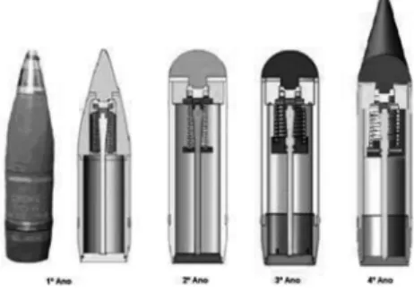
Previous versions were designed based on a 105mm smoke projectile by a reverse engineering process because one of the requisites was that the FIREND should be fully compatible with the howitzers and the tabular firing tables used by the Army (Lima, 2005). In the first year of project the external profile of FIREND was similar to the smoke projectile. The most significant modification from the first projectile was made at the second year of development and was related with the external profile (Dias, 2007). An hemisphere fuze was adapted because of the need of a higher impact area to actuate the mechanical ejection system of the projectile and the body was also adapted to increase inner space, as shown in the Figure 1.
The mechanical mechanism of FIREND works as described:
• The fuze is pushed behind with the impact while the rest of the body maintains its inertia and the generated energy is used to cut a fusible membrane; • The cut of the fusible membrane interrupts the connection between the
main body and the shaft and releases the spring;
• The accumulated elastic energy of the spring is released and is use to eject the projectile cover and the cargo.
3. FIREND FUNCTIONALITY TRIALS
The functionality trials consisted on evaluating the performance of the projectile under real launching conditions. The trials were conducted at Escola Prática de Artilharia in Vendas Novas using a M101 A1 105mm/22 howitzer (Castanheira, 2012). The obtained results give some conclusions: • The chosen rotating band was not adequate because there was an incomplete
obturation;
• The aerodynamic component Dummy (the conical component of Figure 1) is not needed because the projectile has shown stable flight behaviour; • The 1mm fusible membrane was not strong enough to support the launching forces; • The impact dispersion was lower than expected;
• The ejection system was ineffective because the projectiles penetrated in the ground before ejecting the cargo;
• The components are expected to be reused because there was no visible damage on them after the impact.
4. INOVATIONS
This project has three main differences from the FIREND. The projectile caliber was raised from 105mm to 155mm. The fuze was mechanical and now is electronic. And the fuze is now actuated by an altimetry system instead of contact actuation. The caliber raise is justified by a greater cargo capacity, longer range and because 155 shells are more compact since there is no need of cartridge cases. The electronic fuze was implemented to achieve better response times of the ejection system and to increase compatibility with the altimetry system. The altimetry system will allow the ejection’s height adjustment. This implementation enhances the projectile effectiveness because it will eject the cargo before the impact with ground avoiding the projectile ground penetration and the loss of fire
fighting capability and also nullifies the dependence of the ground characteristics. The altimetry system has been developed by other MSc thesis.
The electronic fuze induces other change related to the ejection system. The lack of compatibility between the electronic fuze and the spring justifies the use of other component with accumulated energy. Micro gas generators like the ones used at vehicles airbags were chosen to substitute the spring (see Figure 2). The micro gas generators are capable of producing approximately 1 MPa of pressure (Mosa, 2008) in hundredths of a second (BE, 2008), which can deliver the force to eject the base of the projectile and the cargo. The base is supported by three set screws that are cut by the base when the interior pressure of the projectile increases.
Figure 2 - Gas generator for drivers airbag (Mosa, 2008).
The decision to use gas generators offers some advantages: the gas generators are small and maximize cargo volume, the generated gas is inert and contributes to fire fighting (Yang, 1995) and they are commercial off-the-shelf components. The use of these innovations confers the projectile a cargo volume approximately 7x larger than FIREND.
5. PROJECT REQUIREMENTS AND CONSTRAINS
Some requirements were established in the project of the projectile and their components:
• The projectile design and its ejection system have to be compatible with the altimetry system;
• The projectile has a caliber of 155mm;
• The projectile dimensional and weight characteristics should be very similar to the same characteristics of a conventional projectile, which in this case is a M107 High Explosive Grenade;
• The cargo compartment should be sealed to preserve the cargo and protect the electronic components;
• When possible, commercial components and usual dimensions should be used to reduce production time, costs and waste.
The first requirement related to the altimetry system is justified by the need to improve the projectile effectiveness while the larger caliber in relation to FIREND is justified by the greater cargo capacity.
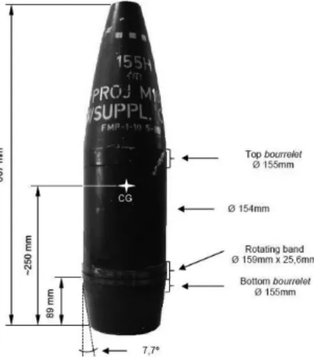
The dimensional and weight characteristics are related to the use of the existing tabular firing tables. These tables help the artillery personnel adjusting the howitzer to correctly aim the target. The tables have some values and the corrections to those values that take into account projectile variations, weather, Coriolis effect and other variables. To use the existing corrections the fire fighting projectile should hav e the same shape, weight and center of gravity of the conventional projectile. It is impossible to have equal characteristics because the fire fighting projectile has a cylindrical shape so the intention is to have the most approximate values of weight and center of gravity relative location. Some external dimensions are equal to the M107 grenade, which was measured by a reverse engineering process (see Figure 3).
Figure 3 - M107 HE Grenade principal external dimensions.
The cargo compartment sealing is essential because the cargo may be a liquid or a fine powder. This type of cargo may pass through the connections between projectile parts and also reach the electronic components located in the fuze compromising the correct operation from the fuze.
6. GENERAL CONCEPT
The projected projectile has the same shape of FIREND but the external dimensions are similar to the M107 HE grenade.
The fire procedures of the fire fighting projectiles are the same of conventional shells firing procedures. Operational differences only appear at the final trajectory phase. The altimetry system monitors the projectile altitude and generates a signal when an established altitude is reached. At that moment the gas generator is triggered the ejections sequence is started. The sudden pressure and temperature raise is transmitted to the cargo and consequently to the base. Finally the set screws are cut and the cargo is ejected.
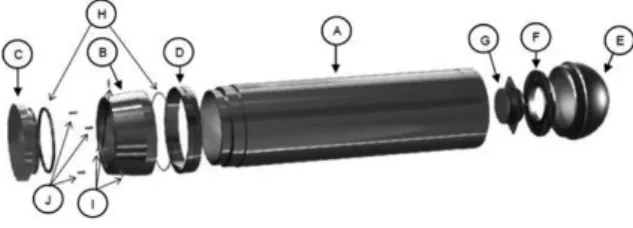
Seven components and three groups of components were defined. As shown at Figure 4 these are: main body (A), secondary body (B), base (C), rotating band (D), fuze body (E), fuze cover (F), gas generator (G), o-ring group (H), screw group (I) and pin group (J).
Figure 4 – Projectile in exploded view.
The AISI 1045 steel was chosen as reference material for components. This option is due to the material good machinability, good mechanical resistance, relatively cheap and available on the market (F. Ramada, 2012).
7. COMPONENTS
Main Body (A) – This component is the frame of the projectile and 90% of cargo is transported in it. The group consisting of main body and secondary body is called the projectile chassis. It was decided to separate the chassis because of the intention to reuse the components. Not all components will suffer plastic deformation. This depends of the soil characteristics and impact velocity. The components will only be reused if certified by a metrological analysis that assures the dimensional tolerances of the parts.
At the front end (see projectile direction) there are thread zone A to assemble the rotating band and thread zone B where the secondary body is linked. At the rear
end there is a bourrelet (Cinta de guiamento) that is a part of the projectile having the same diameter as the bore of the howitzer barrel.
The DIN 20MnV6 steel was chosen as the material to produce this component because is better steel than AISI 1045 and it is available as seamless hollow tube, which respects the requirement related to commercial components.
Figure 5 - Main body in perspective view.
Secondary Body (B) – This component (see Figure 6) belongs to the chassis and is responsible of transmitting the forces applied on the base to the main body. Its shape affects the projectile aerodynamics during flight. According to a research (Timmers, 2004) the ideal shape of this chassis part has ¾ caliber of length and a conicity angle of 7º.
Figure 6 - Secondary body in perspective views.
At the bottom there are three blind holes for alignment pins and three through holes for base supporting set screws.
The material that was chosen to this component is the DIN 20MnV6 steel by the same reasons as the main body.
Base (C) – The base (see Figure 7) has two main functions. First it has to support the developed pressures at firing moment and second it should quickly disassemble of the chassis when the ejection process begins. To comply with these functions the base was dimensioned taking into account the maximum obtained pressure by the M4A2 firing charges in use by
Portuguese Army (DSM-EP, 1987), approximately 304 MPa (US-AARDC, 1980) and was supported by three set screws that will act as mechanical fuses. The base also has three blind holes for alignment pins and three threaded holes for the set screws.
AISI H13 tool-steel was chosen to produce the base because of its thermal and mechanical properties.
Figure 7 - Base in perspective view.
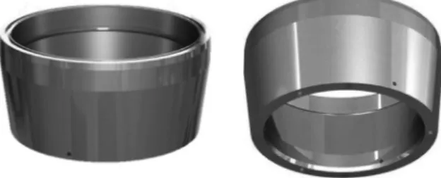
Rotating Band (D) –There are two functions related to this component (see Figure 8). It is responsible for giving the projectile its rotative movement, which is essential for flight stability and is also responsible for howitzer barrel obturation so that all generated gases are availed.
Figure 8 - Rotating band in perspective view.
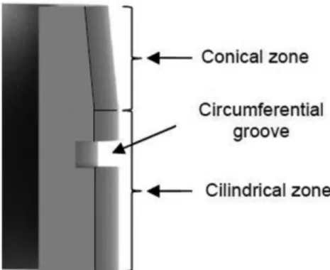
“Because the rotating band is intended to act as a gas seal (obturator) as well as the rotational driver, designs typically exhibit a diameter over the band that is slightly larger than the groove diameter of the weapon. The engraving action of the gun lands and the interference fit in the grooves causes a plastic flow of the band resulting in a pressure on the band seat as well as a developed reaction in the gun wall. This pressure can be greater than the gas base pressure on the projectile” (Carlucci, 2008). This pressure is called the interface pressure and is extremely prejudicial to the barrel. To decrease the stresses caused by this pressure a circumferential groove was cut into the band surface (see Figure 9). This groove allows the band material to flow, which substantially reduces interference pressure. It also as a conical zone to facilitate the entrance in the barrel as shown in Figure 9.
The chosen material was CuZn5 R340 brass.
Figure 9 – Detail of the rotating band.
Fuze Body (E) – Fuze body is the projectile part where the altimetry system is going to be installed. The set of fuze body, fuze cover and altimetry system conjugates the projectile’s fuze. This set has the same functionality of a conventional fuze and this is the reason why the set is also called fuze. The fuze body has the same hemispheric shape of FIREND’s fuze but is hollow to accommodate the altimetry system and has a hole to allow the altimetry system’s measurement group to calculate the distance to the ground (see Figure 10). The chosen material to make the fuze body is AISI 1045 steel.
a) b)
Figure 10 - Fuze componentes: a) Fuze body; b) Measurement group.
Fuze cover (F) – The fuze cover (see Figure 11) is the division between the cargo compartment and the altimetry system compartment. It simultaneously gives support for the gas generator. The division between compartments is completed by the gas generator, which fills the fuze cover hole.
Figure 11 - Fuze cover in perspective view.
Gas Generator (G) – This commercial component is the energy source for the ejecting system. It has to rapidly increase internal pressure and consequently cut the set screws, eject the projectile base and eject the cargo. The gas generator is “plug and play”, which allows to be assembled moments before firing and it is easy replaceable if needed. The chosen gas generator for the projectile is the MOSA MDS-1 (Mosa, 2008) (see Figure 12).
Figure 12 - MOSA MDS-1 gas generator.
O-ring Group (H) – This group is composed of five o-rings. They were included in the project because of the sealing requirement. Each connected part, except the rotating band is improved with an o-ring. The Figure 13 illustrates a group of o-rings.
Screw Group (I) – This group features two different screws. There are 4 DIN 84 slotted cheese head machine screws and 3 DIN 916 socket set screws (see Figure 14).
a) b)
Figure 14 - Screw group: a) DIN 84; b) DIN 916.
The DIN 84 screws are used to fix the gas generator to the fuze cover as shown in Figure 15. It was opted to use a stainless steel class because these screws are in direct contact with the cargo.
Figure 15 - Gas generator fixed with
DIN 84 screws.
The set screws are used to support the projectile base and should be cut at the ejection process (see Figure 16).
Figure 16 - Base with fastened set screws.
Pin group (J) – This group features the alignment components of the base. It is composed of 3 DIN 7dowel pins, which are fixed on the secondary body as shown in Figure 17 to help with the base assemble.
a) b)
Figure 17 – Pin group: a) DIN 7 dowel
pin; b) Assembled pins on secondary base.
8. 155mm Fire Fighting Projectile
The final result of designing and dimensioning of the projectile is shown in Figure 18.
a)
b) c)
Figure 18 – Major dimensions: a) Top
view; b) Bottom view; c) Side view.
Important volume and weight data is presented in Table 1.
The data of Table 1 identifies the weight zone of the fire fighting projectile. The weight zone is a parameter used in the tabular firing tables and is marked directly on the projectile as certain number of squares. These squares are visible in Figure 3 at the top of the M107 TNT grenade and are related to the grenade weight by zones, as shown in Table 2.
Table 2 - Weight zones (DoA, 2003).
9. CONCLUSIONS
This master thesis had a significant contribute to the author’s judgement development about artillery projectile’s mechanical design and had shown the multidisciplinary universe of this topic. It was necessary to have some imagination and ingenuity to improve the effectiveness of FIREND and at some points innovate without completely losing its initial concept. A strong knowledge base of this project was collected and now it allows to continuously improving the 155mm fire fighting projectile.
Although the mechanical detonation of FIREND was unique it has shown not to be the most effective so it was introduced an electronic detonation actuated by an altimetry system, which allows the user to define more precisely when and where the projectile will spread the cargo and substantially reduces the weight and volume associated to the spring system.
The use of 3D CAD software proved to be an enormous help for designing and dimensioning the projectile and its components. SolidWorks allowed to simulate the presence of a cargo and to calculate essential mass properties and
dimensions. The major result was an increase of approximately 7 times more cargo volume. It is estimated that the cargo can actuate on an 75m2 area. As a final conclusion, it is expected that the 155mm projectile provides an effective mean for fire fighting, which can be used in countries with large forests and the ability to fire 155mm artillery shells, such as Portugal. These facts allow us to forecast high economic potential for the project.
REFERENCES
CASTANHEIRA, Carlos (2012). “Fabrico e ensaio Balístico em Condições Reais de Conceito Melhorado de um Projétil de Detonação Mecânica”. Master Thesis, Portuguese Military Academy and Instituto Superior Técnico, Lisboa, Portugal. LIMA, Francisco (2005). “Desenvolvimento de um Projéctil de Detonação
Mecânica”. Master Thesis, Portuguese Military Academy and Instituto Superior
Técnico, Lisboa, Portugal.
DIAS, Eduardo (2007). “Desenvolvimento do Conceito, Fabrico e Ensaio de um
Projéctil Mecânico para Combate a Incêndios Florestais: FIREND”. Master Thesis,
Portuguese Military Academy and Instituto Superior Técnico, Lisboa, Portugal. Mosa. (2008). “MOSA MDS-1 Driver-side AIRBAG Inflator”. Mosa Industrial Corporation. Available online from: http://www.twmosa.com/airbag/pd_mds1.htm. BE (2008). “Airbag Deployment in Slow Motion”. Biodynamics Engineering, Inc. Available online from: http://www.biomechanics.com/
YANG, Jiann C. and GROSSHANDLER, William L. (1995) . “Solid Propellant Gas Generator: An Overview and Their Application to Fire Suppression”. International Conference on Fire Research and Engineering. International Conference on Fire Research and Engineering, Orlando, Florida, USA.
F. Ramada (2012). “Catálogo Interactivo de Aços e Ligas”. Available online from: http://www.ramada.pt.
TIMMERS, Heiko (2004). “Special Topics of Military Physics”. University of
New South Wales, Canberra, Australia.
DSM-EP (1987). “Fichas de Material, Volume 5 - Munições, Explosivos e Artifícios”. Direcção do Serviço de Material, Exército Português, Lisboa, Portugal. US-AARDC (1980). “MIL-C-60395C - Charge, Propelling, 155MM, M4A2,
Loading, Assembling and Packing”. US Army Armament Research and
CARLUCCI, Donald E. and JACOBSON, Sidney S. (2008). “Ballistics: Theory
and Design of Guns and Ammunition”. CRC Press, TAaylor & Francis Group.
Boca Raton, FL, USA.
DoA (2003). “TM 43-0001-28 - Army Ammunition Data Sheets for Artillery
Ammunition”. Technical Report from Department of the Army, Washington, USA.
João Calado is a Lieutenant from the Ordnance Corps of Portuguese Army. He holds a Master degree in Military Mechanical Engineering from the Portuguese Military Academy.
José Borges holds a Professor position with the Portuguese Military Academy where, among several teaching and administrative duties, he is Scientific Coordinator of the Military Mechanical Engineering Master course. He is a Research Associate with CINAMIL.
Luís Reis is an Associate Professor with the Mechanical Engineering Department from Instituto Superior Técnico. He develops his research activities with IDMEC - Institute of Mechanical Engineering.