University of Beira Interior
Computer Science Department
Master of Science Thesis
Towards a formally designed and
verified embedded operating
system: case study using the B
Method
by Andr´
e Brito Passos
Supervisor: Sim˜
ao Melo de Sousa
Co-supervisor: Jos´
e Miguel Faria
Contents
Contents
i
List of Figures
iv
List of Tables
v
1
Introduction
3
1.1
Context
. . . .
3
1.1.1
Motivation
. . . .
3
1.1.2
The choice of the B Method
. . . .
4
1.1.3
Cautionary notes about formal methods
. . . .
5
1.2
Definition of the work
. . . .
6
1.2.1
Objectives
. . . .
6
1.2.2
Contribution
. . . .
6
1.3
Outline
. . . .
7
2
Software Engineering and the B Method
9
2.1
System Modeling and Design
. . . .
9
2.2
Formal Development Life Cycle
. . . 12
2.3
B Method language
. . . 13
2.3.1
Abstract machines
. . . 14
2.3.2
Refinements and Implementations
. . . 15
2.3.3
B Architecture
. . . 15
2.3.4
The B language
. . . 17
2.4
Example
. . . 20
2.5
B tools
. . . 24
2.5.1
ProB
. . . 24
2.5.2
Atelier B
. . . 26
2.5.3
B-Toolkit
. . . 26
2.5.4
Rodin
. . . 27
i
2.5.5
U2B
. . . 27
2.5.6
Brama
. . . 27
2.5.7
Final Remarks
. . . 27
2.6
Summary
. . . 28
3
Secure Partition Kernel
29
3.1
General Overview
. . . 29
3.2
Secure Partitioning kernel Protection Profile
. . . 31
3.3
Secure Partitioning Microkernel
. . . 32
3.3.1
Time Partitioning
. . . 35
3.3.2
Space Partitioning
. . . 35
3.3.3
Security Partitioning
. . . 36
3.4
Proposed Solution
. . . 38
3.5
Prex microkernel
. . . 39
3.6
Summary
. . . 43
4
State of the Art
45
4.1
Verified Microkernels
. . . 45
4.2
The B Method in the Verification of Microkernels
. . . 53
4.3
Summary
. . . 53
5
Formal Development of a Secure Partitioning Microkernel
55
5.1
General strategy
. . . 55
5.2
Formal specification of the Secure Partitioning microkernel
. . . . 56
5.2.1
Machine Ctx
. . . 56
5.2.2
Machine CtxMemory
. . . 58
5.2.3
Machine MemoryManagement
. . . 59
5.2.4
Machine Clock
. . . 62
5.2.5
Machine Messages
. . . 63
5.2.6
Machine PoolForCommunication
. . . 65
5.2.7
Machine KernelCommunication
. . . 66
5.2.8
Machine Scheduling FIFO
. . . 71
5.2.9
Machine Interface
. . . 72
5.2.10 Animation with ProB
. . . 73
5.3
Partition Information Flow Policy
. . . 74
5.3.1
Machine FlowPolicy
. . . 75
5.3.2
Machine Matrix
. . . 77
5.3.3
Machine BASIC IO
. . . 77
5.3.4
Machine FlowPolicy Imp
. . . 78
5.3.5
Machine Matrix Imp
. . . 80
5.4
Prex with Partitioning Information Flow Policy
. . . 81
CONTENTS
iii
5.6
Summary
. . . 84
6
Conclusion
87
6.1
Contribute
. . . 87
6.2
Challenge
. . . 87
6.3
Future Work
. . . 88
Bibliography
89
A B components
95
A.1 Machine Ctx
. . . 95
A.2 Machine CtxMemory
. . . 95
A.3 Machine MemoryManagement
. . . 96
A.4 Machine Clock
. . . 98
A.5 Machine Messages
. . . 99
A.6 Machine PoolForCommunication
. . . 101
A.7 Machine KernelCommunication
. . . 102
A.8 Machine Scheduling FIFO
. . . 105
A.9 Machine InterfaceMachine
. . . 106
A.10 Machine FlowPolicy
. . . 111
A.11 Machine Matrix
. . . 112
A.12 Machine BASIC IO
. . . 113
A.13 Machine FlowPolicy Imp
. . . 114
A.14 Machine Matrix Imp
. . . 116
B Example Configuration File
119
B.1 Config File
. . . 119
1.1
Diagram with the complete work
. . . .
7
2.1
Standard development life cycle and formal development life cycle
. . 12
2.2
Abstract machine representation
. . . 14
2.3
Refinement mechanism
. . . 16
2.4
A B project
. . . 16
2.5
Diagram of Balzer’s software life cycle
. . . 17
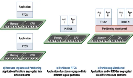
3.1
Evolution of partitioned systems
. . . 30
3.2
Common Criteria certification chain
. . . 32
3.3
Mills architecture
. . . 34
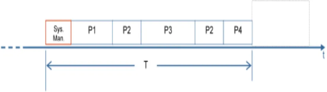
3.4
Static scheduler period
. . . 35
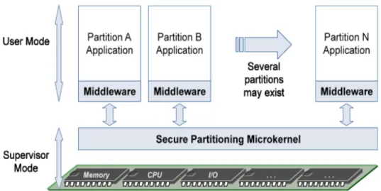
3.5
Secure partitioning microkernel architecture
. . . 36
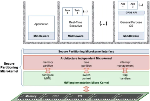
3.6
Prex microkernel structure
. . . 39
3.7
Microkernel memory mapping
. . . 40
3.8
Thread states
. . . 41
3.9
Message passing sequence
. . . 42
3.10 Message transfer in Prex
. . . 43
5.1
Architecture of the abstract model for the secure partitioning
micro-kernel
. . . 56
5.2
States and possible transitions for tasks
. . . 59
5.3
Example of a possible state for the pool for communication
. . . 65
5.4
Behavior of the operation cleanEmptyPorts
. . . 72
5.5
Example of ProB animation
. . . 74
5.6
Partition Information Flow Policy Architecture
. . . 75
5.7
Prex and Partition Information Flow Policy
. . . 81
List of Tables
3.1
CC Evaluation Assurance Levels
. . . 32
3.2
Partition Abstraction
. . . 37
3.3
Least Privilege Abstraction
. . . 38
5.1
Global state of PIFP project
. . . 83
5.2
Possible configurations for two tasks
. . . 84
Acknowledgements
First of all, I would like to thanks to Professor Sim˜ao Melo de Sousa, who always helped me giving me the precise directions to conclude this work.
In second to Critical Software. It was an extraordinary experience the development of this thesis in a company like Critical. In particular I would like to thanks to my co-supervisor and good friend, Jos´e Miguel Faria, for all the support, help and freedom of thinking. To the formal methods team, Pedro and Ricardo, always by my side during the time spent in the developing of this work. A word to Pedrosa for all the time wasted explaining me some doubts about operating systems. To all the colleges in Critical Software, I prefer not to say names because all were outstanding.
To my girlfriend, Marina Taramelo, for all the support and encouragement during these hard times for both. At last, to my friends and my family, namely my mother, Elisabete and father, Daniel, who gave me the opportunity of study.
For all of you: Thanks!
Chapter 1
Introduction
The formal development of software systems is the subject of this thesis. More precisely, the development of a verified microkernel using the formal specification language, B Method. This chapter introduces the main concepts of this work.
1.1
Context
In some contexts formal methods are considered as the best means available for developing safe an reliable systems. One well-known researcher, Bertrand Meyer, express the necessity and efficiency of formal methods when he wrote about software engineering: “It is clear to all the best minds in the field that a more mathematical approach is needed for software to progress much” [29]. The goal and the results of this work can be seen as an other proof of evidence of the previous fact.
1.1.1
Motivation
According to R.W. Butler [23], “formal methods refers to mathematically rigorous tech-niques and tools for the specification, design and verification of software and hardware systems”. The phrase “mathematically rigorous” means that specifications used in formal methods are well-formed statements in a mathematical logic and that the formal verifications are rigorous deductions in that logic (i.e., each step follows from a inference rule and hence can be checked by a mechanical process). A method is formal if it has a sound mathematic basis, typically given by a formal specification language. The value of formal methods is that they provide means to symbolically examine the entire state space of a digital design (whether hardware or software) and establish a correctness or safety property that is valid for all possible inputs. However, this is rarely done in practice today (except for the critical components of safety critical systems) because of the enormous complexity of real systems.
The activities of modeling and formal reasoning are supposed to be performed before under-taking the effective coding of a computer system, so that the software in question can be correct by construction. Formal methods can be very helpful at this point. But, why formal methods are not widely used instead of typically software engineering? Formal methods should be used by people who have realized that the program development process they using is inadequate, or in industry when the customer pretend to use such methodology. Another reason that may
recommend the use of formal methods is that fact that certain standards like Common Criteria (EAL 5-7), EN 50128 (SIL 4) and DO-178B (Design Assurance Level A and B), recommend or requires the use of formal methods. At this stage is possible to question why to bother about formal methods and not use tests and simulation instead. Limitations related to tests, like the problem of how to exactly define a good test and the representativeness are difficult properties of achieve. Nevertheless, exhaustiveness for the general case of all the set of possible values is infinite, so, total coverage is an impossible task. Like W. Dijkstra once said “Program testing can be a very effective way to show the presence of bugs, but is hopelessly inadequate for showing their absence”. Software correctness is the holy grail, being chasing for some time. Formal methods are not the “perfect solution” but can provide an effective help with in the dealing with bugs.
There are cases where the use of formal methods is a requirement, but which formal method should we use? The choice of a formal method is not easy. Partly because there are many. To decide which formal method to use, a number of questions should be posed:
• Is there any theory behind your formal method? • What kind of language is your formal method using?
• Does there exist any kind of refinement mechanism associated with your formal method? • What is your way of reasoning with your formal method?
• Do you prove anything when using your formal method? • Have you got an efficient automatic prover?
These questions should work like a conductive method to help in the quest of the adequate formal approach. Several other criteria should be analyzed, like for example, the experience in the use of a specific formal method. Other important criteria is the usage purpose. Some kind of formal methods have a large and successful experience in specific areas and types of certification. For example, the B Method is used in the Railway System sector and in the process of certification SIL 4 (see for instance [37][7]).
1.1.2
The choice of the B Method
Engineering disciplines require tools for engineers to reason about the possible solutions for their problems. It is very common to see mechanical engineers working with tools to design, make some measures and experiments before passing to the “real world”. These tools are mathematical tools that work with models to make measurements about the work. Strangely, or not, computer science evolution happened very quickly, and some steps were not so well done. Formal methods provide a large variety of tools to help engineers to reason about the system. These tools are used to specify a system’s desired behavioral and structural properties, like done in other engineering disciplines. The reveal of ambiguities, incompleteness and inconsistency in systems are the main objectives in the usage of such tools. Properties that characterize well formal methods are: (i)exhaustiveness, the formal reason over the possibly infinite set of values; (ii)rigor, well established mathematical foundations; and (iii)adequacy, provided tools and techniques are evaluated as adequate means for providing evidences of reliability. The use of formal methods to reason about systems is called formal specification.
The existence of a rather large set of tools with different and more or less restricted domain of application is a convenient property. This means that depending on the purpose of the appli-cation, one or other formalism can be better applied. In the following sequel some considerations will be done about the several formalisms. It is not pretended to make a state of the art in the area, only to give a brief perspective of what exists.
Formal specification can be classified in mostly two families. In algebraic specifications give more importance to the data being manipulated. This means that the behavior of the
1.1. CONTEXT
5
system is expressed by the data of the system, how this data evolutes along the time, or how the different data relates to each other. On the other hand, it is possible give more meaning to the operations of the system. The behavior is expressed by the operations, internal mechanisms or by the system actions. In this type of formalism, the specification is the modifications that operations can perform in the internal state this is called a model based specification. Other types of organization can be given, for example, based on their prime domain of application, i.e., either specialized in sequential programs, or focusing on concurrent and distributed systems.
Z, VDM and B are well established and representatives of specifications based on models. Petri nets, CCS, CSP or event-B are also model based but with their prime domain of application being concurrent and distributed systems. On the other hand, for algebraic specifications, ACT-ONE, CLEAR, OBJ, SPECWARE, etc. can be used for sequential programs and LOTOS, etc. for concurrent and distributed systems.
Temporal requirements plays an important role in some systems. Model based approaches offers a quite variety of solutions for express temporal requirements. However, transitions be-tween states change, requiring a temporal requirement for a transition to proceed. Tools that can be used with this type of formalism are Lustre, Esterel, Scade, UPPAAL, etc..
As previously said, formal methods can be used to achieve correctness. To verify this prop-erty, normally, desired properties are confronted with the specification of the system/algorithm. Correctness of a system can be verified by writing proofs by hand or use more or less automatic tools. Model checkers, Proof systems (also known as theorem provers) and proof assistants are the main groups used to mechanically verify the correctness of a system.
Proof assistances generally require some user intervention. They can check whether a given proof is valid, according to the rules of deduction of the logic concerned, or, given a theorem and its premisses, try to discover a proof such that the theorem follows from that premisses [16]. Examples of proof systems are Coq, HOL, Isabelle and PVS.
Model checking is an alternative to proof systems. They are specially suitable for the analysis (modeling) of concurrent systems. The properties are expressed in temporal logical formulas and the verification is performed exploring the possible transitions of the system. Some of the advantages, comparing with the previous ones, are the automatic demonstration of the properties without any user intervention and the exhibition of a counter-example. The disadvantages are the problem of state space explosion and the fact that model checker do not know how to deal with infinite sets. Examples of model checkers are SMV, SPIN, Kronos, UPPAAL, etc..
Other formalism that in our days is being used for several systems is design-by-contract. The logical annotation of the program using Hoare Logic. Each function is annotated with a pre-condition and a post-condition, like a contract. Then, the source code is confronted with the contract to perform validation. The notion of invariant is also present in this type of formalism, to express the global properties of the complex components of the system. Usually, this type of verification is very connected to the language. With C we have Frama-C (with jessie plug-in), for Java we have JML, for C] we have Spec] and for Ada we have Ada/Spark.
The goal of this work is to start with an high-level abstraction, defining the properties of the system and them refine only part of the system to be developed. It was pretended a methodology that covers all the stages of the development process and the B Method is in concordance with this criteria. Some previous experience and some examples showed that is possible to use the B language to perform such work [?] [22]. The B Method does not deal well with concurrency and real time requirements. However, the microkernel to be developed it is not a real time kernel and the concurrency problems will not be part of the problem to be analyzed.
1.1.3
Cautionary notes about formal methods
Even perfect program verification can only establish that a program meets its spec-ification. [...] Much of the essence of building a program is in fact the debugging
of the specification. [18]
Beware of bugs in the above code; I have only proved it correct, not tried it. By Donald Knuth.
Formal methods provides a close relationship with requirements. Validation can start sooner and more easily auditable. This property really strengthens the role of formal methods in the development process. More sooner the validation starts more quality the final product will have. A typical problem pointed to formal specification is the fact that an abstraction can be proved correct. But is this specification really doing what is supposed to do? Are the properties well defined to that specification? These questions are now, more or less, answered using animators. This type of tools can give to the person which is specifying the system a certain view and understanding of the specification. Animators permits to animate, run the specification. So, it helps solving the problem of what is the specification really doing.
As seen in the previous section1.1.2, different formalisms can be applied in different fields of application. A tool that permits to solve in an efficient and satisfactory way all type of problems is still not known.
1.2
Definition of the work
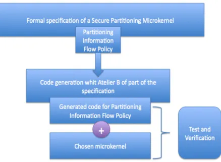
The aim of this work is to produce a embedded microkernel using the B Method. To perform this objective the work was divided into three stages. In the first stage it is necessary to provide a complete requirements analysis and a specification of a secure partitioning microkernel. This is done using the tool Atelier B and ProB for animation.
The second stage is composed by a complete development of part of the secure partitioning microkernel. The chosen part was the partitioning information flow policy (PIFP). Starting with a high level specification, the partition information flow policy is the refined until be possible to generate automatically code.
The third and final part is the integration of the code generated with a chosen microkernel. In this part is necessary to perform a verification/testing over the microkernel with the generated code. Figure1.1illustrates the diagram of the three stages of the work.
1.2.1
Objectives
The overall objective is the complete development of a secure partitioning microkernel using the “correct by construction” paradigm (more precisely the B Method). The other objectives are:
• Perform a complete specification using the B Method; • Use and exploration of the B tools (ProB and Atelier B); • Proof of correctness for the system;
• Reach a level in the development process where it is possible to automatically generate code;
• Integration of part of the microkernel in a real word system;
• Explore the use of the chosen formalism in the context of microkernel development.
1.2.2
Contribution
The microkernel is the principal part of an operating system. Being the operating system, the place where applications run, it becomes easy to understand that a special careful in the
1.3. OUTLINE
7
Figure 1.1: Diagram with the complete work
development of a microkernel is very important. It make essential the usage of formal methods to help in the construction of a microkernel. The contribution of this work is to perform a complete formal development of the microkernel. As secondary contribution, the transfer of knowledge from the university to the companyCritical Software.
1.3
Outline
This thesis is organized in six chapters. Chapter1introduces the main concepts that are subject of study in this thesis. Chapter2gives a brief overview about software engineering with formal methods and presents the B Method. Chapter 4gives an overview about the state of the art involving formal verification for kernels. Chapter 3 presents the work that are to be developed, giving an overview of what is a secure partitioning microkernel and the proposed solution. Chapter 5 presents the work developed, a formal model of the secure partitioning microkernel and the complete development of part. Integration with the target microkernel is also presented. Chapter 6concludes this thesis by describing the most relevant conclusions of the work herein described.
Chapter 2
Software Engineering and the B
Method
In this chapter a description of the B language and methodology will be provided (based on [6]). The aim of this chapter is to prepare the reader for the next following chapters. The goal is not to give a complete overview of the language but only to illustrate the main concepts. For a full description of the language, methodology and mathematical foundations it is recommended to consult [3].
This chapter will be organized in the following way, in the first section a presentation of what is modeling, how to make a good model and other normal descriptions when dealing with this type of formalism. Next, in section2.2, it is described what is the formal development life cycle, showing the different phases.
After talking about the software development process, it is described the B language (section
2.3). Concepts like abstract machine, refinement and implementation will be explained. The B methodology also will be presented.
An example for making more clear the concepts around the language is given in section2.4. It is a quite simple and easy to understand, but at the same time complete enough for show the application of the B Method.
In section2.5it is presented a description of the tools normally used in the B language. Each tool has a different utility in the development life cycle, the usage of each one in the different parts can give a precious help in the development process.
In the end (section2.6), a summary for the all chapter will be given.
2.1
System Modeling and Design
Computer Science, like other engineering disciplines, requires a complete view of what is to be done. Engineering design is used to each a complete view and understanding of the problem.This technique is composed by two concerns. The first one is the world view, how the system should behave in the real world. Normally in this phase we are thinking about the system, about its properties. The second one is how to use the technology to achieve a real world view. In this stage we are already thinking in one possible implementation to solve our problem. A technique that deals with both concerns is called modeling.
Usually, in the classical approach a very competent domain-expert person whose main source of inspiration comes from previous systems that he has done is who makes the engineering design. Preceding experiences brings some strengths but also some weaknesses like old and bad habits. Validation of such studies is accomplished by a number of tests and reports to see if the results are consistent with previously decided criteria. An approach that completes the former is namely based on formal (mathematical) description, refinement techniques, decomposition and mechanized proofs. In this approaches the requirements document sometimes are not a valid input because generally it is a mental implementation of the desired system, one good input is a document with the addition of the expected properties for the system.
The main idea of this new way of study the system consists in using models with a certain correctness criteria, with which we can use mathematical simulation, which is not very different from the usual method of tests, except for its exploitation technique. The difference using mathematical simulation is that we will not look to the result to see if it respects the criteria, but to prove that the model respects it. Like J.R. Abrial refers [23], this change in the mode of exploitation of the “simulation” has a number of interesting consequences:
• Rather than using a simulation language in order to build our model under the form of a simulation program, we are going to use directly a mathematical notation, which will allow us to represent the model in a way that will be more convenient than a simulation program (for expressing the statements and for proving them).
• Rather than limiting ourselves to a single simulation program, as is usually the case, we can very well use a series of embedded models that are supposed to be refinements of each others. In this way, the various criteria to prove can be accumulated and proved immediately at their right level of abstraction: the proof process accompany the model elaboration process.
• Once a model has reached a dangerous level of complexity (so that the proofs might become cumbersome), it will be possible to decompose it into separate model: the architecture is born.
So, what is a model? Everyone has a vague idea of what is a model, but is important to give a precise notion to define a formal construction. Models provide a demonstration of some properties (mathematical properties) of a system without necessarily building the system. Modeling requires an abstraction, at a certain level, of the future system. The idea is to put ourselves mentally above the system and try to imagine what we could observe from there. Simple properties or laws that sometimes are forgotten became obvious and these are the ones that we want to catch at a first view. We can now have our first model, a very simple one dealing only in the basics of the system.
The advantages of modeling in the early stages are quite obvious, mistakes can now be found sooner, so a lot of time can be spared. Another advantage is that we can reach a point in our model where we find some inconsistencies, which can tell us that we are not understanding well the problem possibly because some requirements are missing.
These advantages of modeling are not a surprise inside engineering disciplines. In fact, it is quite normal for a mechanical engineer to make a first model and then make some measure-ments over the model to see if the behavior is the expected one before pass to the phase of building. Models using a mathematical base notation provide us with the capacity of making measurements. Basically what we want to model using mathematical notation is the important characteristics of some “thing” that we will next build or implement, to reveal what our “thing” will look like, to help us understanding how our “thing” will behave, and finally to make sure that our “thing” achieves the required behavior. The main purpose of modeling is to construct correct software by construction and this technique is called software modeling.
Software can go wrong and cause very expensive damages. Ariane 5 is a good example of software failures with expensive results. It took the European Space Agency ten years and
2.1. SYSTEM MODELING AND DESIGN
11
seven billion of Euros to produce Ariane 5, a giant rocket capable of hurling a pair of three-ton satellites into orbit with each launch and intended to give Europe overwhelming supremacy in the commercial space business. A research taken by Le Lann concludes that the real causes of the failure are faults in the capture of the overall Ariane 5 application/environment requirements, and faults in the design and the dimensioning of the Ariane 5 on-board computing system. These faults result from not following a rigorous system engineering approach, such as applying a proof-based system engineering method (for more details see [26]).
In software modeling we are centered only in the expect behavior of the system. Therefore, we try to achieve an abstraction of the system and focus on what we desire for that system and not in how we will implement those desired functionalities. Like mentioned before the notion of abstraction can be seen as observing the system from a higher view. In these observations we need to have two notions: a notion of objects (static notion) and a notion of movement (dynamic notion). The first one refers to the state of the model and the second one the events or operations that may occur and that we are able to observe. The properties connected to the state of the system are called safety properties and those related to events or operations are called liveness properties. The two properties need to be proved; they have no reason, a priori, to be coherent. Software modeling can be differentiated in three phases:
1. Specification: is concerned with what the system should do. There is no requirement that a specification needs to be executable. Specifications model the user or world view of the system, not the internal behavior;
2. Refinement or Design: is the process of transforming the specification towards an implementation. This must be achieved without changing the world view;
3. Implementation: is the final refinement or design step in which we make the model executable. Implementation is concerned with how the system is to be realized.
In order to clarify the three phases presented it will be used an analogy called the parachute paradigm. Suppose that we are suspended in the air by a parachute, we are looking to our system behavior from a upper level. From that view we only see some properties of the system, this properties need to be proved to see if we are thinking correctly. At this time that we finished our proves and we have seen all the properties form that level, we can step down a little bit and thus observe some other interesting things, that is, a more precise properties which we were not able to distinguish before because we are in a too higher level. New properties (safety and liveness) will appear and and these new observations should not invalidate the previous ones, instead they should rather make them more accurate. Now we can step down a little bit more and so on. This is called the parachute paradigm.
What we have just briefly view here is the notion of what we call refinement of our models in order to have a gradually more precise view of all the facts of the system. Comparing with the tree phases of system modeling when we are in the upper level we are dealing with the specification phase. Every time we make our model more precise, we are refining the model, making him more accurate. The last step is the when we are in the lower level, the implementation phase. One import property to stress at this point is that all the properties that are proved at a certain level remain valid along the path leading gradually to the ground. An important fact is when we start modeling a certain system, we are at a higher level of abstraction so is very common to start with a single and very simple model. When we start refining the model, more properties appear and the model starts becoming complex and large. This is the right moment to envisage decomposing the model into several sub-models. The role of the decomposition is clear. Once separated from the main body, a sub-model can be developed further independently from the rest of the system, which becomes its so-called environment. It is important to notice that decomposition is the process used here, this does not mean that composition is impossible, it only means that we cannot compose existing parts without the
supervision of a decomposition process. This is the only way to ensures that some global laws are maintained while decomposing parts are working together.
Abstraction problem is the tentative of achieving a good abstraction level. At the very beginning, when we start modeling, if we are thinking in loops or sequential composition, the best thing to do is stop and start all again. We are going in the wrong direction, not thinking correctly in terms of abstraction. The best way to see if we are in the right level of abstraction is to think about the problem like an interface, this is, do not think in details of how to resolve the problem but think in what to do. Of course that be in the right abstraction level is a difficult task and that most people refers as the major art for modeling correctly.
Modeling is an art, and like other arts we can be good at it or not. I truly believe that getting the write level of abstraction and modeling correctly is a task that, like other, tasks requires a lot of work not because of its difficulty, but because it is different from what is usually done. As a result, it is a question of mentality rather than difficulty.
2.2
Formal Development Life Cycle
To build formally developed applications is necessary to follow a precise and formal de-velopment life cycle, like the one mentioned in [3]. Informal statements should be enriched, structured and formalized progressively. Each phase of the construction progress is carried out according to the needs and constraints of the following phases. Results achieved at each phase can be reused by the next one, which optimizes the process and assures good traceability across the phases.
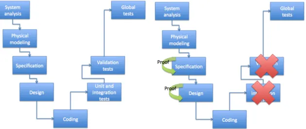
Standard development life cycle and the formal development life cycle (Figure2.1) are ap-parently similar in their form. However, formal development life cycle is shorter in the number of steps. The first phases for both the life cycles are the system analysis and the physical modeling. In this phases, informal requirements are taken into account. The capabilities of the software to be developed and the constraints are described in this phase. In both life cycles the procedures are the same. Although, it is recommend that for the formal software development cycle some requirements should be written in a more formal way. Applying this technique, it becomes more easy to express, in the next phases, the requirements to the formal specification [23]. Going
Figure 2.1: Standard development life cycle and formal development life cycle
2.3. B METHOD LANGUAGE
13
which functions the software must perform in order to have the desired capabilities.The way of dealing in this phase is completely different in the different life cycles. In the formal devel-opment cycle, the analysis of the problem lead us to define an abstract solution that meet the requirements. The solution is organized from the most abstract to the most detailed and con-crete, using a top-down approach. The result is a collection of formal components organized in an architecture describing the dependencies and a decomposition of functions and data. Using this methodology, functions are transformed into operations in the specification language. Data is transformed into variables and operation parameters. Basically, the properties collected from the requirements are decomposed in several parts over the specification. The invariant plays an important role in this process. Properties that are pretend to hold through the all development are specified in the invariant. So, safety and functional requirements are distributed across a set of invariants. In the standard process, it is frequent to found models in UML to help in the specification of the problem. UML can be very helpful to understand and achieve the solution for the problem.[35]
After the specification phase, the objective is the production of an eventual executable program from an implementation programming language. In the standard development process, some code obtained from the UML models is re-utilized. The programmer respects the models generated in UML and implement a solution for the desired functionality. In the formal life cycle, the executable code of the software is obtained by translating, either automatically or manually, the models.
For the testing phase, in the standard development cycle, it can be divided in three sub-phases. It will be described very briefly each one:
• The unit test phase, that checks each procedure of each sub-program; • The integration tests phase, that checks the cooperation of sub-programs;
• The validation tests phase, that checks the adequacy of the program with respect to the requirements.
In the formal development cycle, tests are also divided into three sub-phases. Unitary tests concern exclusively operations of abstract machines not formally refined and implemented and operations that could not be proved completely. Integration tests concern the integrity of for-mally and not forfor-mally developed modules. As in conventional developments the functional tests are performed normally.
One particular aspect is the substitution of unit, integration tests and validation tests by proofs. Validation proofs is carried out at preliminary and detailed design phases by the validation team. Validation may be based on a number of techniques, the two main ones being formal proof and model checking. When proving a system (that it follows a given behavior), the used proof tool can do it automatically or interactively. In both cases a formal proof is constructed. Tools dedicated to automatic proof construction are called theorem provers. Interactive proof systems are usually referred as proof assistants. Proof tools can be used a diferent stages of the development cycle, but their common usage lies in the validation and design stage where they are used o prove that no erroneous behavior can occur.
2.3
B Method language
At present various formal methods exist and new ones are likely to appear. What is the best formal method is a question that in the opinion of the author depends on the purpose and utility of the system. Essentially two approaches have been developed; one is to express the behavior of a program or a system in an abstract way, a model, and then proof mathematically the consistency of the system. The second one is to attempt to prove properties using an already existing code as input. The B Method is based on the first approach.
B is a tool-supported formal method based on Abstract Machine Notation (AMN), used in the development of computer software. It was originally developed by Jean-Raymond Abrial in France and the UK. The B method due to J.R Abrial is a formal method for the incremental development of specifications and their refinements down to an implementation. The method of software development based on B is known as the B Method. It is a model-based approach similar to Z and VDM. At each step of the B development some proof obligations are generated, enabling the verification of refinement as well that of abstract machine consistency.
AMN provides structuring mechanism which support modularity and abstraction in an object-based style, making provable correctness a realistic and achievable goal through system development. The method is based around the concept of layered development, which constructs larger components from collections of smaller ones.
The B notation is strongly marked by simplicity forcing the user to use well-understood program statements, so only the simplest programming statements are included within B. Struc-turing, management and control of large volumes of detail in large software systems is a difficult task.To verify their combination and their relationships is very hard without the notion of re-finement. The structuring mechanisms provided by the B method are also characterized by simplicity, and are designed particularly with verification in mind.
Developing based in invariant assertions provides consistency conditions between compo-nents. These invariants hold the document together and give rise to proof obligations which can be used to guarantee its correctness.
The B language is an extensive language, rich in details and full of proper constructions. The aim of these following sections is not to provide all the details but to give an overview of the different aspects in the language.
2.3.1
Abstract machines
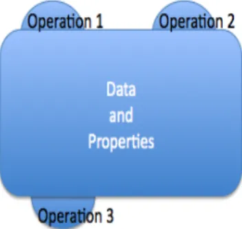
The basic mechanism in the B Method is the abstract machine, it defines in different clauses, data and its properties as well as operations. They represent the base definition of what the pro-gram components will do, i.e. the minimal functionality that satisfies the propro-gram requirements. Various known programing notions, like modules, classes or abstract data types are concepts very close to abstract machines. A machine contain variables and operations. Variables are encapsulated by the machine and operations enable the access and manipulation of machine variables.
Figure 2.2: Abstract machine representation
Mathematical concepts such as sets, relations, functions and sequences are the elements that describe the basic machines. One central concept in abstract machines are the static laws. This concept, defined by predicates, constitute the invariant of the abstract machine. Variables when changed by operations must always obey to the invariant. Operations behavior is specified
2.3. B METHOD LANGUAGE
15
formally using generalized substitutions to change predicates. A given operation can have a pre-condition: it is a predicate expressing the conditions necessary to invoke the operation. Operations can also contain an action: it is a substitution describing how the variables of a machine are manipulated.
Abstract machines belong to the specification phase. Sequencing and loop substitutions are forbidden in this phase. So, the supposed is to describe what an operation should do, not how. A good way of dealing with this limitation is thinking in terms of nondeterminism because it leaves open choices for further developments. Parallel substitutions are used instead of sequencing, order for the application of this type of substitution is no applicable. A mechanism for the verification of the invariant is necessary for guarantee that the substitutions applied by the operations preserve the invariant. Proof obligations are constructed from the formal definition of the substitutions in the abstract machine. If proof obligations are proved then the invariant is always true. This mechanism ensures the correct behavior of the machine ensuring that the predicates defined on the invariant always remain true.
2.3.2
Refinements and Implementations
Refinement is a technique used to transform the “abstract” model of the software system (its specification) into another mathematical model that is more “concrete” (its refinement)[3]. Refinement can be performed in three different ways: the removal of the non-executable el-ements of the pseudo-code (pre-condicions and choice), the introduction of classical control structures of programming (sequencing and loop), and the transformation of mathematical data structures (sets, relations, functions, sequences and trees) into another structures that might be programmable (simple variables, files, or arrays). So, refinement is basically applied to the operations and data of the abstract machine. The refinement can be applied using various steps, this is for guarantee the careful control of the transformations. During each step, the initial abstract machine is entirely reconstructed. It keeps, however, the same operations, as viewed by its users, although the corresponding pseudo-code is certainly modified. In the intermediate refinement steps, we have a hybrid construct, which is not a mathematical model anymore, but certainly not yet a programming module.
The final step in the refinement is the implementation. An implementation is a ultimate level of refinement of an abstract machine. It is written using a B language sub-set called B0 language, which has the following characteristics. The implementation data must be concrete data (scalars, arrays) that are directly implemented in a high level language like C. Also the body of the implementation is made up of concrete and sequential substitutions, called instructions, that are directly executable in a high level programming language.
During each refinement, operations refinements need to be proven compatible with the operation that refine. The proof of refinement guarantees that the code of the refinement will conform to its specification in the abstract machine. A picture showing the refinement mechanism is presented in Figure2.3.
2.3.3
B Architecture
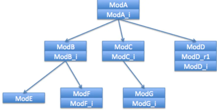
A complete development in B corresponds to a B project. A project enables formally modeling a system of any type. Mechanisms of decomposition and composition of abstract machines are used to accomplish a project. As soon as the level of complexity of the refinement of the abstract machines reaches a point where is too high, it is recommended to decompose it into several, more simple parts. The implementation can then be implemented on the specification of one or more several abstract machines, which are themselves refinable. This is done using the IMPORTS clause and calling the operations of the imported machines. Using this methodology, it is possible to construct a B project gradually, according to an architecture made from layers of
Figure 2.3: Refinement mechanism
abstraction. Figure2.4illustrates a possible example of a B project. It is possible to see in the
Figure 2.4: A B project
picture that the project is composed by several modules. The arrows represents IMPORT links. The modules are made up of B components. A module has the following properties: it always has an abstract machine, representing the module specification. It may have an implementation (components finishing with “ imp”) and possibly some refinements (components finishing with “ r”).
The formal development using the B Method fills exactly in the Balzer Software fife cycle
2.5. A formal specification (in which a mathematical text – the machine – is written prescribing “what” the intended software system should do) is linked to (one or more) implementation. The intended coherence between these two phases is achieved by means of a justification, a mathematical document saying “why” the implementation meets the abstract model. This can be done gradually using a technique called refinement.
2.3. B METHOD LANGUAGE
17
Figure 2.5: Diagram of Balzer’s software life cycle
In essence, the life mentioned life cycle is composed by:
• Informal Specification – The costumer exposes the problem, which is textually defined via informal requirements;
• Formal Specification – The development team builds a mathematical mode of the requirements (several machines in the B Method). This procedure describes the formal understanding of the problem by the team;
• Prototype Machines are animated to see if they correspond to the expected functional behavior. The customer can provide also some input to see if the model correspond to the expectations;
• Formal Specification – If the model does exactly what is expected, then, it is refined and formally verified using proof obligations for check the internal consistency. The B Method uses internal mechanism to verify the correctness;
• Code – After reach an implementation level, the code is automatically generated using the appropriated B tools.
As can be seen by the previous stages, the B Method fulfills all the stages of the Balzer life cycle.
2.3.4
The B language
Basically the B language is a composition of four elements: • Components (abstract machines, refinements, implementations) • Predicates
• Expressions • Substitutions
Components
Like mention before, components can be an abstract machine, a refinement or an imple-mentation. Components are composed by a set of clauses describing the static and dynamic properties of the behavior. The main clauses are:
• MACHINE – declaration of the machine name and parameters if them exists; • REFINEMENT – declaration of the name of a refinement;
• IMPLEMENTATION – declaration of the name of an implementation; • REFINES – clause used to declare the name of the refined component;
• IMPORTS – when a implementation imports an abstract machine, it can use the imported machine operations. However it can not use the imported machine data. This is one of the main principles to achieve decomposition;
• SEES – when a component sees another, it can consult its data and use operations in which do not modify these data;
• INCLUDES – when an abstract machine includes another abstract machine it integrates the data of the included machine;
• PROMOTES – when a component promotes another it is possible to promote operations belonging to machine instances created by the component, this means that the operations promoted from the imported machine pass to belong to the promoting machine; • EXTENDS – special case of the promotes, in which all operations of the imported machine
are promoted;
• DEFINITIONS – declaration of purely syntactic translation. These textual definitions will be expanded in the component before any further analysis. This feature is similar to ]def ine in C and C++, but one definition cannot use another one within the same machine;
• CONSTRAINTS – declaration of properties of the machine’s parameters; • SETS – declaration of abstract and enumerated sets;
• CONCRETE CONSTANTS – declaration of constants, concrete and implementable, which will be kept during successive refinements;
• ABSTRACT CONSTANTS – declaration of abstract constants, which are non-implementable and must therefore be refined. Constants may be members of sets, sets, or functions; • PROPERTIES – declaration of the constants’ properties;
• CONCRETE VARIABLES – declaration of concrete variables, which are implementable and will be kept during the successive refinements. The list of variables is separated by commas. What these variables represent, their types, properties and relationship between them are contained in the invariant clause;
• ABSTRACT VARIABLES – declaration of abstract variables, which are non-implementable and must therefor be refined;
• INVARIANT – declaration of invariant properties of the variables. This is the logical assertion about the system which shall always hold (”a safety constraint”), but, more importantly, defines what the machine really is. Within it, all variables types, properties, and relationships are defined. It is the most difficult part of the specification to produce, since the invariant must be strong enough to hold information about the system without contradict itself;
• ASSERTIONS – declaration of the “facts” that derive from the invariant. They are mostly used to make proof easier;
2.3. B METHOD LANGUAGE
19
• INITIALISATION – initialization of variables. When the “machine” starts the variables initialized in this clause need to stay true and do not break the invariant;
• OPERATIONS – declaration of the operations in the form of a header and a body. This represents the actions that can be performed with the variables.
Predicates
Predicates are a subset of the logic of first logic predicates. They are formulas that can be proved or disproved or that may be part of the assumptions used to determine the proof. Predicates are used to express properties for the components data. An important utilization is in the expression of the invariant clause, in which the predicates express the properties of the variables. Another kind of utilization is in the pre-conditions under which operation can be called (these conditions relate amongst others to input parameters of the operation).
Predicates are also used to express Proof Obligations. Hypotheses under which the proof is made and that can help in the proof or refutation of the goal are also presented in predicates.
The predicates of the B language are grouped in the following families:
• simple propositions (conjunctions, negation, disjunction, implication, equivalence), • quantified predicates (universal, existential),
• comparison predicates between predicates. Expressions
Expressions are formulas describing data. Every datum has a type and a value. The categories of expressions are:
• basic expressions; • boolean expressions; • arithmetic expressions; • expression of couples
• set expressions (empty set, set of integers, boolean, ...); • set construction (set of sub-sets, union, intersection, ...);
• relation expressions (identity, inverse, projection, composition, iteration, domain, ...); • function expressions (injections, surjections, bijections, ...);
• function constructions (constant functions, lambda expressions, ...). Substitutions
Generalized substitutions are mathematical notations defined as predicate transformers. They are used to describe the dynamic behavior of B components, this is, their operations.
The description of the behavior with generalized substitutions is used for abstract ma-chines, refinements and implementations. The specification of the substitutions can be non-deterministic and non-executable if we are in the abstract, refinement level of abstraction. Whereas in the implementation level, substitutions correspond to instructions of a classic com-puting language.
Generalized substitutions are also used for proof obligations construction. This process is automatically achieved using the B components. For example, the proof obligation correspond-ing to the presentation of the invariant durcorrespond-ing the call of an operation is constructed by takcorrespond-ing the invariant as hypothesis and the proof of substitution of the operation applied to the invariant as the goal. The substitutions of the B language are:
• substitution becomes equal, substitution becomes such as, substitution be-comes element of:
x := E;
• pre-condition substitution, to express pre-conditions of operation calls: PRE G THEN S END;
• bounded choice substitution, SELECT substitution: SELECT G THEN S END;
• substitutions AN Y and LET which introduce data verifying certain properties: ANY v WHERE P THEN S END,
LET v BE P IN S END; • V AR substitution which introduces local variables:
VAR v IN S END; • conditional IF and CASE substitutions:
IF P THEN S ELSE Q END, CASE E OF EITHER l THEN S OR m THEN T ... OR n THEN U END END • simultaneous substitution: x, ..., y := E, ..., F, x := E||...||y := F ; • loop substitution
2.4
Example
In oder to illustrate the described methodology, a simple example is presented next. First, an informal specification of the problem is given. Then, a B complete development is build, step by step, showing the different aspects of the B language.
The problem was extracted from [3], and the complete solution was presented in [4]. Sup-posing that an hotel wants to develop a system for control the allocation of their rooms. It is necessary to control the rooms available. The operations require are (i) the reservation of an room, (ii) get the number of available rooms and (iii) free an used room.
The first machine to de specified is the Reservation machine. This machine provides the basic operations for the maintainability of the hotel rooms.
2.4. EXAMPLE
21
MACHINE Reservation(nb max) CONSTRAINTS nb max ∈ 1 .. 1000 DEFINITIONS PLACES= (1 .. nb max)b VARIABLES occupied INVARIANT occupied ∈ F(PLACES) INITIALISATION occupied := ∅ OPERATIONS nb ←− free places = BEGIN nb := nb max − card(occupied) END; place ←− reserve= PRE nb max − card(occupied) 6= 0 THEN ANY pp WHERE pp ∈ PLACES − occupied THENplace , occupied := pp, occupied ∪ {pp} END END; freePlace (place)= PRE place ∈ PLACES ∧ place ∈ occupied THEN
occupied := occupied − {place} END
END
Reservation machine receives a formal parameter called nb max, this is the number of rooms available for the hotel. The property that the formal parameter needs to be between 1 and 1000 is declared in the CONSTRAINTS clause. The formal parameter is also used in the DEFINITIONS clause. Here it is defined the numerated set PLACES, that represent the number of available places that the hotel has.
The variable occupied tells the places that are occupied and the ones that are not. This variable is typed in the INVARIANT clause as a finite set of the type PLACES.
The machine is composed by three operations. The first operation is the free places, that returns the number of free places. It is quite simple to understand how it works, if we subtract the number of places actually used in the hotel, represented by occupied, to the total number of places, we obtain the number of free places. The next operation is reserve. In this operation a pre-condition is presented. It is necessary the hotel to have free rooms to make a reservation.
In the body of this operation is used non-determinism to chose one available room. Selecting a place that belong to PLACES but do not belong to occupied we obtain a free room. Using non-determinism it is possible to think in what we want to do and not in how. This can be very helpful in the specification phase.
The final operation is freePlace. This operation receives an occupied room and free the room for further use. The parameter of the operation needs to be a room belonging to the occupied rooms.
This machine is far away of being an implementable machine. We are using sets, and this type of structure is not implementable in common languages. We are dealing with the specification of the problem. Defining in the abstract machine the properties of our system.
Since we have already defined our properties, we can step down a little bit and try to refine the machine. The firs refinement consists in substituting the free variable representing the number of free rooms by one variable (nb free), the second replacement is change the variable occupied for one function characteristic (state) which associates the places with a boolean. state ( tt ) = TRUE ⇔ pp ∈ occupied
Applying this property to the invariant we obtain the following formula: occupied = state−1[{TRUE}]
The modifications of the operations are simple reformulations which try to complete the changes in the refined variables.
REFINEMENT Reservation r1(nb max) REFINES Reservation DEFINITIONS PLACES= ( 1 .. nb max )b VARIABLES state CONCRETE VARIABLES nb free INVARIANT state ∈ PLACES → B ∧ nb free ∈ 0 .. nb max ∧ occupied = state−1[{TRUE}] ∧ nb free = nb max − card(occupied) INITIALISATION
state := PLACES × {FALSE} k nb free := nb max OPERATIONS nb ←− free places = BEGIN nb := nb free END; place ←− reserve = BEGIN
2.4. EXAMPLE
23
ANY pp1 WHERE pp1 ∈ state−1[{FALSE}] THEN place := pp1 k state (pp1) := TRUE k nb free := nb free −1 END END ; freePlace ( place ) = BEGINstate (place) := FALSE k nb free := nb free + 1 END
END
The final step is to reach implementation. The variable state (total function) can be implemented importing the machine from the basic library provided from B, BASIC ARRAY VAR. This machine accepts two parameters (domain and range) to form a relation. In our case, the domain is the set with the possible values for the number of places (1..nb max) and the range is the set of BOOL. Basically, this machine encapsulates the relation state from the previous refinement using an array. The imported machine provides two operations, STR ARRAY to set a value in the relation and VAL ARRAY to get a value from the relation. To respect the previous refine machine, it is necessary to initialize with FALSE, all the values in the range of the relation of the imported machine.
The invariant clause in the Reservation i implementation, connects the invariant of the refined machine and the invariant of the imported machine. They both are total functions. IMPLEMENTATION
Reservation i(nb max) REFINES
Reservation r1 IMPORTS
BASIC ARRAY VAR(1 .. nb max, B) INVARIANT state = arr vrb INITIALISATION VAR ind IN nb free := nb max ; ind := 1;
WHILE ind ≤ nb max DO STR ARRAY(ind,FALSE); ind := ind + 1
INVARIANT
ind ∈ 1 .. nb max + 1 ∧
(1 < ind ⇒ arr vrb[1 .. ind −1] = {FALSE}) VARIANT
nb max + 1 − ind END
OPERATIONS nb ←− free places = BEGIN nb := nb free END; place ←− reserve = BEGIN VAR ind,bb IN ind := 1; bb ←− VAL ARRAY(ind); WHILE bb = TRUE DO
ASSERT ind < nb max THEN ind := ind + 1;
bb ←− VAL ARRAY(ind) END
INVARIANT
ind ∈ 1 .. nb max ∧ bb = arr vrb(ind) ∧ FALSE ∈ arr vrb[ind .. nb max]
VARIANT nb max − ind END; STR ARRAY(ind,TRUE); nb free := nb free −1; place := ind END END; freePlace ( place ) = BEGIN STR ARRAY(place,FALSE); nb free := nb free + 1 END END
This small example is only intended to show the previous presented concepts. To be a complete example it is necessary to have another machine working like a ”main” machine, providing the operations offered by the Reservation machine. Another important aspect, not presented, is the discharging of the proof obligations. It is necessary to proof at each step that the refinement or implementation respects the refined machine.
2.5
B tools
Tools play an important role in the development and validation of software. The B Method has a large variety of tools that can help in the different phases of the software development. A perspective of the most commonly used is present here.
2.5.1
ProB
ProB is an animator and model checker tool for the B-Method [27]. Due to the fact that is an animator, the user can see the behavior of the models and interact with it. This is an
2.5. B TOOLS
25
important feature because it gives some confidence of what is modeled. On the other hand, model checking, the other feature of ProB, exhaustively explores the model.
To perform animation and exploration of the B machines in ProB, it is necessary to restrict the given sets of the machine into restricted small numeric ranges. Doing this it becomes possible to determine the enabled operations and allows the checking of all the reachable states of the machine with finite types. Manually exploring the B machine many problems can be found, such as invariant violations, deadlocks (states where no operation is applicable) or other unexpected behavior not described in the invariant. Model checking will also notify when all states have been explored; this situation guarantees the absence of errors in that space (restricted space defined by the size of the sets). When no limitation is performed, the exploration of the state space will happen until it finds an error or runs out of memory. The algorithm used by ProB is a mixed from depth-first breath-first strategy. A random factor decides whether a given node will be treated in depth-first or breath-first. Typically two types of errors are found when exploring a first machine:
• Systematic errors inside an operation that occurs in most states. Here is not important to locate a particular state, just to systematically try out all operations for all arguments; • Error when the animation is performed long enough (e.g. deadlock errors). Here it is often not important which particular path is taken, just that the machine is animated long enough.
Typically, depth-first strategy is good picking out errors from the first time, but may fail in the second type. Breath-first strategy works in the reverse way.
Exploring the machine operations it is possible to reach states where the invariant, by some reason, is violated. This is called a counterexample. When a counterexample happens, an alert message and the steps performed to reach that invalid state are showed. This type of consistency checking can be very helpful when used as an complement to interactive proof; the error that result in a counterexample should be eliminated before attempting any iterative proof. Consistency checking detects the following conditions:
• Invariant violation errors;
• Assertion violation errors (assertions are properties of a B Machine that should follow from the invariant);
• Deadlock errors;
• User-specific goal predicate becomes true.
Another useful concept in the use of this tool is for refinement. The B Method requires a gluing invariant to be provided in the refinement. Sometimes the refinement does not hold and it may take a while for the B developer to realize that the proof obligations cannot be proven, resulting in a lot of wasted effort. Whit ProB an automatic refinement checker can be used to locate and understand errors before any formal refinement proof be attempted.
It is important, at this point, to refer the different types of analysis to consistency checking. A consistency checking counterexample is a sequence of operations calls that leads to a violation of an invariant in a single machine. A refinement counterexample is a sequence of operation calls that is allowed in a refined machine but is not allowed in its abstraction.
It is obvious that this tool should be seen as a complement to other tools that permit verification by proof-based. Another important point is that this tool should be seen as a sophisticated debugging and test tool and not a verification tool.
In the last version of ProB, 1.3.0, other features are included. Currently, ProB is included as an additional plug-in to the Atelier B. This was true, sometimes ago, in the Rodin platform. Another additional feature is the possibility to use temporal model checking. ProB provides Linear Temporal Logic (LTL) has an extension to the B language.
2.5.2
Atelier B
Developed by ClearSy, Atelier B, is an industrial tool that allows the operational use of the B Method to develop defect-free proven software. It offers an environment for management of projects in the B language. Main functionalities provided by the tool can be groped in:
• Proof aid. To demonstrate proof obligations using suitable proof tools;
• Development aid. Automatic management of dependences between B components; • User comfort tools. A graphical representation of projects, display of project status and
statistics and project archiving.
Atelier B is a complete framework for the development of complete projects using the B language or Event-B. Type checking is the first phase of the verification of a machine. Syntax analyzer is provided to verify the B files. A grammatical verification is performed and a certain number of contextual verifications including the type control and the control of identifier scopes. Compo-nents need to pass to the type checker before passing to the next phases. Automatic generation of proof obligations is the next phase. A component, specified in B, is only correct when all its proof obligations are demonstrated. Two methods for discharge proof obligations are provided. In proof automatic mode, most of the proof obligations are demonstrated without user interven-tion. The remaining proofs need to be verified using an interactive mode. In this case, the user guides the prover in its proof obligations demonstration using interactive commands (lemma additions, proof by case, etc.). When there are no remaining proofs, i.e. the entire project is proved, the B0 checker enters in action. The function of the B0 checker is carrying out a verification of the specific machine is in the B0 language (a sub-division of the B language), to ensure that a model can be translated to the target language. The version used of Atelier B is version 4.0. This version is free and only permits generation of code to the target language C. On the last phase, the project checker checks all the components of a project to control its architecture (the links between the components). The project must be checked before the final translation of the project.
Additional tools are provided to help in the development phase. For example, BART is an automatic refinement tool. BART permits the refinement and implementation generation using refinement rules expanded by the user. Additional refinement rules can be added for refinement personalization of certain components. To help in the documentation, B models can be saved in pdf, rtf and LaTeX formats.
2.5.3
B-Toolkit
B-Toolkit, the tool provided by B Core, is the concurrent tool for Atelier B in the devel-opment using the B Method. The B-Toolkit comprises a suite of fully integrated software tools designed to support a rigorous or formal development of software systems using the B Method. Like in Atelier B, it is provided a set of functions to help in the management of all associated files, ensuring that the entire development, including code and documentation, is always in a consistent state. The main functionalities can be divided into tree sub-groups, a configuration management of the project, a proof-based mechanism for formal verification and a set of tools for help in the documentation. Configuration management checks the dependency between components. A set of software specification and analysis tools, which includes syntax check-ers, type checkers and a specification animator. For formal verification it is used a proof-based mechanism. This type of mechanism ensures the generation of automatic proof obligations and automatic and interactive prover. A set of documentation generation tools for automatically producing fully cross-referenced and indexed type-set documents from source files. Gathering all this functionalities it is provided a complete framework to the development of complete projects using the B language.