AXIAL BUCKLING LOAD OF PARTIALLY ENCASED
COLUMNS UNDER FIRE
ABDELKADIR FELLOUH
Final thesis presented to
School of Technology and Management
Polytechnic Institute of Bragança
For the fulfilment of the Master degree in
CONSTRUCTION ENGINEERING
AXIAL BUCKLING LOAD OF PARTIALLY ENCASED
COLUMNS UNDER FIRE
ABDELKADIR FELLOUH
Final thesis presented to
School of Technology and Management
Polytechnic Institute of Bragança
For the fulfilment of the Master degree in
CONSTRUCTION ENGINEERING
Supervisor at IPB:
Prof. Paulo Piloto
Supervisor at UHBC: Prof. Nourredine Benlakehal
My thanks go especially to my parents who supported me from the beginning. I also thank the supervisors of the thesis, Dr. Paulo Piloto, coordinator Professor from the Department of Applied Mechanics, School of Technology and Management, Polytechnic Institute of Bragança, and Dr. Nourredine Benlakehal, Department of Civil Engineering, Faculty of Civil Engineering and Architecture, University Hassiba Benbouali of Chlef.
I thank all my professors especially from IPB Dr. Luís Mesquita and Dra. Elza Fonseca and from UHBC Dr Lamri Belkacem and Dr. kada Abdelhak for helping, support and encouragement.
Partially encased columns have significant fire resistant. However, it is not possible to assess the fire resistance of such members simply by considering the temperature of the steel. The presence of concrete increases the mass and thermal inertia of the member and the variation of temperature within the cross section, in both the steel and concrete components. The annex G of EN1994-1-2 allows to calculate the load carrying capacity of partially encased columns, for a specific fire rating time, considering the balanced summation method. New formulas will be used to calculate the plastic resistance to axial compression and the effective flexural stiffness. These two parameters are used to calculate the buckling resistance. The finite element method is used to compare the results of the elastic critical load for different fire ratings of 30 and 60 minutes. The buckling resistance is also calculated by the finite element method, using an incremental and iterative procedure. This buckling resistance is also compared with the simple calculation method, evaluating the design buckling curve that best fits the results.
KEYWORDS
As colunas parcialmente embebidas com betão possuem elevada resistência ao fogo. No entanto, não é possível avaliar a resistência ao fogo de tais elementos simplesmente considerando a evolução da temperatura do aço. A presença de betão aumenta a massa, a inércia térmica do elemento e a variação de temperatura dentro da seção transversal, tanto no aço como nos componentes de betão. O anexo G da EN1994-1-2 permite calcular a capacidade resistente de colunas parcialmente embebidas com betão, para um tempo específico resistência ao fogo, considerando o método da soma pesada das componentes. Novas fórmulas serão utilizadas para calcular a resistência plástica à compressão axial e a rigidez à flexão efetiva. Estes dois parâmetros são utilizados para calcular a resistência à encurvadura. O método dos elementos finitos é utilizado para comparar os resultados da carga crítica elástica para diferentes classificações de resistência ao fogo, 30 e 60 minutos. A resistência à encurvadura também é calculada pelo método dos elementos finitos, por um processo incremental e iterativo. A resistência à encurvadura é também comparada com o método de cálculo simplificado, avaliando a curva de encurvadura que melhor se ajusta aos resultados.
PALAVRAS CHAVE
INDEX
CHAPTER.1 INTRODUCTION ... 1
1-1- Objective and motivation ... 1
1-2- Fire safety ... 2
1-3- Organization of the thesis ... 4
1-4- State of the art ... 5
CHAPTER.2 COLUMN UNDER FIRE ... 9
2-1- Fire curves ... 9
2-1-1- Nominal fire curves ... 9
2-1-2- Natural fire curves ... 10
2-2- Heat transfer ... 14
2-3- Materials properties ... 15
2-3-1- Thermal properties ... 15
2-3-2- Mechanical properties ... 19
CHAPTER.3 SIMPLIFIED METHOD USING EUROCODE 4-ANNEX G ... 25
3-1- Definition of partially encased column ... 26
3-2- Flanges of the steel profile ... 29
3-3- Web of the steel profile ... 30
3-4- Partially Encased Concrete... 30
3-5- Reinforcing bars ... 32
CHAPTER.4 NEW PROPOSAL FORMULAE FOR ANNEX G ... 35
4-1- Introduction ... 35
4-2- Fire effect on the flange component ... 35
4-3- Fire effect on the web component ... 36
4-4- Fire effect on the concrete component ... 38
4-5- Fire effect on the reinforcement component ... 41
CHAPTER.5 NUMERICAL SOLUTION METHOD ... 43
5-1- Elements used in numerical models ... 43
5-1-1- Thermal model ... 43
5-1-2- Structural model ... 45
5-2- Convergence test ... 46
5-3- Thermal analysis ... 47
5-6- Non-linear Buckling analysis ... 54 CHAPTER.6 COMPARISON OF RESULTS ... 57 CHAPTER.7 CONCLUSIONS ... 61
ANNEX
1- SIMPLIFED CALCULATION METHOD………..A-3
2- SUMMATION OF FOUR COMPONENTS………..A-13
3- THERMAL ANALYSIS FOR 3M OF HEIGHT (ANSYS)………..A-23 4- EIGEN BUCKLING ANALYSIS FOR 3M OF HEIGHT……….…A-35 5- EIGEN BUCKLING ANALYSIS FOR 5M OF HEIGHT……….A-57
5- BUCKLING ANALYSIS FOR 3M OF HEIGHT………..A-81
LIST OF FIGURES
Fig. 1 - Definition of risk class. ... 3
Fig. 2 - Height of building h and reference level. ... 4
Fig. 3 - Nominal fire curves... 10
Fig. 4 - Parameters of localized fire. ... 11
Fig. 5 - Natural fire curves... 12
Fig. 6 - Fire event with a class 1 car vehicle simulated by Fluent software. ... 13
Fig. 7 - Specific heat at elevated temperature. ... 16
Fig. 8 - Thermal conductivity at elevated temperature ... 16
Fig. 9 - Density of steel at elevated temperature ... 17
Fig. 10 - Specific heat at elevated temperature. ... 18
Fig. 11 - Thermal conductivity at elevated temperature. ... 18
Fig. 12 - Density of concrete at elevated temperature. ... 19
Fig. 13 - Curve stress-strain of steel under tention. ... 20
Fig. 14 - Reduction factors for the stress-strain ... 20
Fig. 15 - Curve stress-strain of concrete under compression. ... 21
Fig. 16 - Reduction factors for the stress-train ... 21
Fig. 17 - Curve stress-strain of reinforcement under tension. ... 23
Fig. 18 - Reduction factors for the stress-strain ... 23
Fig. 19- Reduced cross-section for structural fire design. ... 26
Fig. 20 - Example of partially encased column. ... 27
Fig. 21 - Partially encased column under fire. ... 28
Fig. 22 - Isothermal criteria in the cross section... 35
Fig. 23 - Average temperature of the flange. ... 36
Fig. 24 - Web height reduction. ... 37
Fig. 25 - Average web temperature for different standard fire resistance classes. ... 38
Fig. 26 - Thickness reduction of the concrete area for HEB and IPE sections. ... 39
Fig. 27 - Average temperature of residual concrete. ... 40
Fig. 28 - Average temperature of rebars. HEB sections (left). IPE Sections (right). ... 41
Fig. 29 - SOLID70 Geometry (ANSYS16.2). ... 44
Fig. 30 - LINK33 Geometry (ANSYS16.2). ... 44
Fig. 31 - SOLID185 Geometry (ANSYS16.2). ... 45
Fig. 34 - Numerical thermal results for column HEB 360. ... 48
Fig. 35 - Elastic modulus for the three materials. ... 50
Fig. 36 - Example of Buckling shape for different fire ratings classes. ... 51
Fig. 37 - Curve stress-strain of steel, concrete and reinforcement. ... 53
Fig. 38 - Plastic straine of HEB360 for R30. ... 53
Fig. 39 - Buckling mode of HEB240 and IPE330 for different fire ratings classes. ... 55
Fig. 40 - Buckling curve using new formulae. ... 57
Fig. 41 - Ratio between critical and plastic resistance for 3m of height. ... 57
Fig. 42 - Ratio between critical and plastic resistance for 5m of height. ... 58
LIST OF TABLES
Table 1 - Minimum fire ratings for structural elements of buildings. ... 3
Table 2 - Risk building category. ... 4
Table 3 - Mechanical characteristics of steel S275. ... 20
Table 4 - Stress-strain relationship for steel at elevated temperatures. ... 20
Table 5 - Mechanical characteristics of the concrete C20 / 25 ... 21
Table 6 - Stress-strain relationship for concrete at elevated temperatures. ... 21
Table 7 - Mechanical characteristics of steel S500. ... 22
Table 8 - Stress-strain relationship for reinforcement at elevated temperatures. ... 22
Table 9 - Reduction coefficients for bending stiffness around the week axis. ... 25
Table 10 - Characteristics of the sections under study. ... 28
Table 11 - Parameters for the flange temperature ... 29
Table 12 - Parameter for height reduction of the web ... 30
Table 13 - Thickness reduction of the concrete area. ... 31
Table 14 - Average concrete temperature... 31
Table 15 - Reduction factor
k
y,tfor the yield pointf
s,yof the reinforcing bars. ... 32Table 16 - Reduction factor
k
y,tfor the modulus of elasticity of the reinforcing bars. . 32Table 17 - Parameters for determining the temperature in the flange. ... 36
Table 18 - Application limits (HEB and IPE profiles). ... 37
Table 19 - Parameters and application limits for HEB and IPE cross sections. ... 38
Table 20 - reduction in thickness of the concrete (HEB). ... 40
Table 21 - reduction in thickness of the concrete (IPE). ... 40
Table 22 - Application limits for average temperature of the concrete. ... 41
Table 23 – Thermal results from ANSYS [°C]. ... 48
Table 24 - Elastic critical load for 3m height. ... 51
Table 25 - Elastic critical load for 5m height. ... 52
Table 26 - Plastic resistance to axial compression ANSYS. ... 54
Latin upper case letters
c
A
Cross-sectional area of the concrete.s
A
Cross-sectional area of the reinforcement.V
A
m Section factor.E Modulus of elasticity.
a
E
Modulus of elasticity of the structural steel at room temperature. ,
a
E
Modulus of elasticity of the structural steel at elevated temperature.c
E
Effective modulus of elasticity of the concrete at room temperature.cm
E
Secant modulus of elasticity of the concrete at room temperature.
sec, ,
c
E
Characteristic value for the secant modulus of concrete in the firesituation.
EI fi,c,z Effective flexural stiffness of the concrete around the z-axis exposed tofire
EI fi,eff,z Effective flexural stiffness of a composite section around the z-axisexposed to fire.
EI fi,f,zEffective flexural stiffness of the flange around the z-axis exposed to fire.
EI fi,w,z Effective flexural stiffness of the web around the z-axis exposed to fire.
EI fi,s,zEffective flexural stiffness of the reinforcement around the z-axis exposed to fire.
s
E
Modulus of elasticity of the steel reinforcement at room temperature.
,
s
E
Characteristic value for the slope of the linear elastic range of thestress-strain relationship of reinforcing steel at elevated temperatures.
t
H Factor.
y
I
Moment of inertia relative to the axis y-y.z
c
Q
Is the convective part of the rate of heat release.
K The element stiffness matrix.
S Geometric stiffness matrix of the element.L Length of the column.
cr
L
Buckling length.z cr fi
N
, , Elastic critical load (≡ Euler buckling load) around the axis Z in the firesituation.
Rd pl fi
N
, , Normal plastic stress resistant exposed to fire.Rd b fi
N
,, Buckling resistant exposed to fire.
,
T Temperature.
pl
W
Plastic section modulus.Latin lower case letters
b Width of the cross section.
w
b
Width of the web element.fi c
b, Neglected external layer of concrete.
horizontal fi
c
b
, , Neglected external layer of concrete in horizontal directions.vertical fi c
b
, , Neglected external layer of concrete in vertical directions.
a
c
Specific heat of steel.
pc
Specific heat of concrete.cd
f
Design value of the yield strength of the steel at room temperature.cm
f
The average design value of the yield strength of the steel at roomtemperature.
sk
f
Characteristic value of the yield strength of the steel reinforcement atroom temperature
ck
f
Characteristic value of the compressive strength of the concrete at roomhardening.
h Total height of a cross section.
1
h Height between web.
net
h Net heat flow per unit area.
c net
h , Net convective heat flux per unit surface area.
d net
h , Design value of the density of heat flow per unit area.
r net
h , Net radioactive heat flux per unit surface area.
fi w
h
, Height reduction of the web.
,
E
k
Reduction factor for the slope of linear elastic range at the steel
temperature
a reached at time t.
c
k Reduction factor for the tensile strength of concrete.
,
p
k
Reduction factor of the yield point of structural steel giving the
proportional limit at temperature
a reached at time t.
,
y
k
Reduction factor for effective yield strength at the steel temperature
areached at time t.
t
Time.f
t
Flange thickness.w
t
Web thickness.u
Geometric mean of the distances u1u2 .1
u u2
Shortest distance between the reinforcing steel centre and inner face of the flange or the nearest end of concrete.
z
Height along the flame axis.Greek upper case letters
t
z y
x d d d d
d
d
Configuration factor.LT
com LT,,
Value to determine the reduction factor LTat elevated temperature.Greek lower case letters
Imperfection factor, thermal elongation coefficient.c
Coefficient of heat transfer by convection. Parameters to take into account the effect of biaxial bending.
Emissivity of material.
c, Thermal strain of concrete.
p, Thermal strain of pressurising steel.
s, Thermal strain of reinforcing steel.f
Emissivity of the fire.m
Surface emissivity of the member.t fi,
Amplitude charging for fire resistance calculation.a
Temperature of steel profile [°C].c
Temperature of concrete [°C].s
Temperature of reinforcement [°C].g
Gas temperature in the vicinity of the element or in the fire compartment.r
Effective radiation temperature of the fire environment.
t c,
Average temperature in the concrete at time t.c f,
Average temperature in the flange at time t.c w,
Average temperature in the web at time t.c s,
Average temperature in the reinforcement at time t.a
) (
Thermal conductivity.LT
Relative slenderness for lateral torsional bending.
Density.
Poisson coefficient in elastic regime.
Stefan Boltzmann constant.x
Principal stress in the x direction.LT
Reduction factor for lateral torsional buckling.
fi LT,
CHAPTER.1 INTRODUCTION
1-1- Objective and motivation
The main objective is to determine the buckling load of partially encased columns (PEC) under fire, using two different methods (simple calculation method and advanced calculation methods), and also to assess the global three dimensional behaviour of PEC.
The study proposes a new formulae for the calculation method of the plastic resistance to axial compression and for the calculation method of the effective flexural stiffness of partially encased sections using the contribution of the four components of the cross sections, and a comparison is made with the simplified calculation method proposed in the standard EN1994-1-2 [1].
The advanced calculation method is based on a four step calculation process. The first step solves the nonlinear transient thermal analysis to define the temperature of the elements under fire. The second step considers a static and Eigen buckling analysis to define the elastic buckling resistance for specific fire rating periods (30 and 60 minutes). The third step considers the nonlinear incremental solution method to find the plastic resistance of the cross section for specific fire rating periods (30 and 60 minutes). The fourth and finally step considers the nonlinear incremental solution method to find the buckling resistance of partially encased columns for specific fire rating periods (30 and 60 minutes).
The thermal analysis is very important to define the thermal effect on the mechanical properties of three different materials (steel, concrete and reinforcement). Specific temperature fields are applied to the four components of partially encased columns, corresponding to the end of each fire rating period.
The static linear analysis is the basis for the eigen buckling analysis. The solution must be found primarily, assuming an arbitrary load on the partially encased column (usually a unit force). The numerical solution of a linear buckling analysis assumes that everything is perfect and therefore the real buckling load will be lower than the calculated buckling load if the imperfections are taking into account.
the incremental displacement in vertical direction and iterative solution method (Newton Raphson) to evaluate the value of plastic resistance.
To determine the buckling resistance, a similar three dimensional model was defined, but using the buckling mode obtained from the second step (eigen buckling analysis) to reproduce the geometric imperfection, according to standards [2]. This solution method is based on the incremental displacement and iterative solution methods (Newton Raphson).
Partially Encased Columns (PEC) are composite elements with specific features that presents some advantages with respects to other material solutions. These elements are considerably stronger than simple steel column, and (PEC) with smaller sections can be used when compared to reinforced concrete columns. One of the weaknesses is related to fire behaviour, so there is a need and interest in defining (PEC) behaviour in these conditions. The results of this study are intended to formulate new proposals for simplified calculation methods and the validation of the numerical models.
1-2- Fire safety
Fire has always been a very destructive natural and accidental phenomenon. The fire risk will always exist because of fire accidents and also it is impossible to use only incombustible products in building.
The primary goal of fire protection is to limit the probability of death and minimise the property losing in an unwanted fire. The most common objective in providing life safety is to ensure safe escape by giving time to people before the collapse of building. To do this, it is necessary to use more fire-resistant materials in construction and protect the structural elements, finally it is important to alert people to provide suitable escape paths and ensure that they are not affected by fire or smoke while escaping through those paths to a safe place.
separating function during the test without letting flames go through the specimen satisfying a well-defined performance criterion. The insulation is the time in completed minutes for which the test specimen continues to maintain its separating function during the test without developing temperatures on its unexposed surface satisfying a well-defined performance criterion. These criteria can be represented graphically in Fig. 1
Fig. 1 - Definition of risk class.
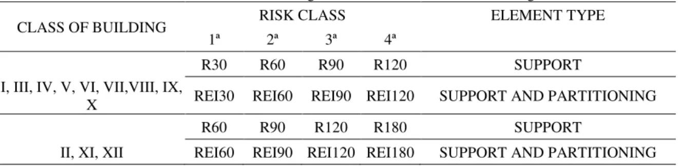
Table 1 presents the fire rating for each building class (I to XII) and risk class (1st to 4th)
Table 1 - Minimum fire ratings for structural elements of buildings.
CLASS OF BUILDING RISK CLASS ELEMENT TYPE
1ª 2ª 3ª 4ª
R30 R60 R90 R120 SUPPORT
I, III, IV, V, VI, VII,VIII, IX,
X REI30 REI60 REI90 REI120 SUPPORT AND PARTITIONING
R60 R90 R120 R180 SUPPORT
II, XI, XII REI60 REI90 REI120 REI180 SUPPORT AND PARTITIONING
Where the class of building is define as: Type I stands for residential; Type II stands for parking places; Type III stands for business buildings; Type IV stands for schools; Type V stands for hospitals and elderly homes; Type VI stands for public shows and meetings; Type VII stands for hotels and restaurants; Type VIII stands for commercial and transport station; Type IX stands for sports and leisure; Type X stands for museums and art galleries; Type XI stands for libraries and archives and finally Type XII stands for industrial and warehouse.
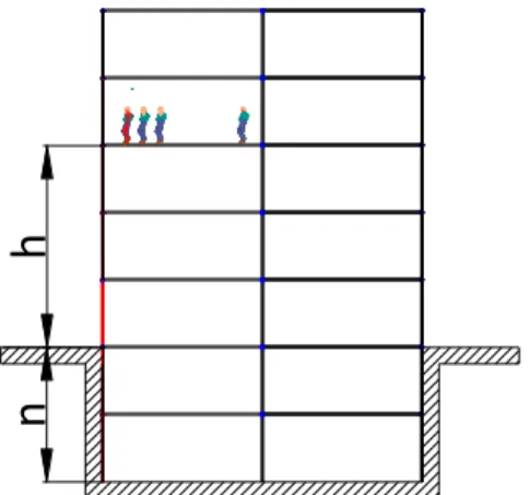
Table 2 - Risk building category. RISK BUILDING
CATEGORY
height of buildings h
Number floors below reference n
1. <= 9 1
2. <= 28 3
3. <= 50 5
4. <= 50 5
Fig. 2 present an explanation of height of building and reference level.
Fig. 2 - Height of building h and reference level.
1-3- Organization of the thesis
The thesis is organised in seven chapters. In the following paragraphs, a brief description of the contents of each is presented.
Chapter 1 is an introduction to the research work presented in this thesis, where the objective and motivation is presented. The state of the art is also included.
Chapter 2 presents the Partially Encased Columns (PEC), with a definition of the mechanical and thermal properties of materials. The fire curves and thermal actions are also explained.
In chapter 3, the simple calculation method is presented and applied to (PEC) when submitted to fire by four sides. This method is based on the weighted summation of four components, according to EN1994-1-2 [1] to determine the buckling resistance of PEC under standard fire ISO834 [4]. The effective flexural stiffness around the weak axis and the plastic resistance of the cross section, are the most important parameters to be calculated.
h
Chapter 4 presents new formulas to be used for the balanced summation method of ANNEX G used to calculate the plastic resistance to axial compression and the effective flexural stiffness. These two parameters are used to calculate the buckling resistance of the columns.
Chapter 5 presents the advanced calculation method for the analysis of the axial buckling Load and the plastic resistance of PEC. Numerical simulations use the finite element ANSYS software with an uncoupled thermal and mechanical analysis.
Chapter 6 presents the results of the advanced calculation method which are compared with the results from new proposed formulae for the simplified method of Eurocode EN1994-1-2 [1].
Chapter 7 presents the main conclusions and proposals for future work.
1-4- State of the art
Partially Encased Columns are usually made of hot rolled steel profiles, reinforced with concrete between the flanges. The composite section is responsible for increasing the torsional and bending stiffness when compared to the same section of the steel profile. In addition to these advantages, the reinforced concrete is responsible for increasing the fire resistance.
Partially Encased Columns have significant fire resistant. However, it is not possible to assess the fire resistance of such members simply be considering the temperature of the steel. The presence of concrete increases the mass and thermal inertia of the member and the variation of temperatures within the cross section, in both the steel and concrete components. The annex G of EN1994-1-2 [1] allows calculating the load carrying capacity of Partially Encased Columns, for a specific fire rating time, considering the balanced summation method.
The behaviour of composite columns made of partially encased steel sections subjected to fire has been numerically investigated by several authors, especially in this decade, but even so only a few experimental studies have been published on these types of columns with restrained thermal elongation. The major part of the experimental studies published until now is on hollow steel columns.
that the concrete cover has a significant effect on the fire resistance, and the lightweight concrete has higher fire resistance compared to normal gravel concrete which has more spalling. Given the fact that the load level is known to play a very important role in the fire resistance of columns.
In 1987, J. B. Schleich [6] was the project leader of an important experimental and numerical campaign developed to test and analyse the behaviour of Partially Encased Columns (PEC) and Beams (PEB) with and without connection to the slab. This project demonstrated the possibilities of the computer code CEFICOSS- which means "Computer Engineering of the Fire resistance for Composite and Steel Structures", able to cover most structural fire applications. This programme CEFICOSS has to be considered as a general thermo-mechanical numerical Computer code allowing to predict the behaviour under fire conditions of structural building parts such as columns, beams or frames. These structural elements could be composed either of bare steel profiles or of steel sections protected by any insulation, either of any composite cross-section type.
Karl Kordina [7] presented tables to be used as fire design guides, based on experiments. These results were verified in PEC and PEB, for certain degree of utilization, supporting conditions and materials.
In 1990 Lie and Chabot [8] tested five concrete-filled circular hollow columns and proposed a mathematical model to predict the temperature distribution within the cross-section and the structural response to fire. The heat transfer analysis is based on a division of the circular section into annular elements, while gas temperature around the section was considered uniform. The effect of moisture in the concrete was considered, by assuming that when an element within the cross section reaches the temperature of 100ºC or above, all the heating to that element drives out moisture until it is dry. This mathematical model was later applied to composite steel-concrete columns with rectangular cross-section and circular composite columns with fiber-reinforced concrete. The same authors presented another study in 1996 on the behaviour of fiber-reinforced concrete-filled hollow columns. The benefits of this type of concrete on the fire resistance of the columns were compared with those of the plain and bar-reinforced concrete.
exposed to high temperatures in the event of a fire. With the currently available data it is not possible to give exact proof of the reliability of the design formulae of the German codes for high strength steel in Partially Encased Composite Columns. Furthermore the extreme weakening of the yield strength under high temperatures severely reduces the efficiency of these columns.
In 2002 Han et al [10] carried out six compressive strength tests on protected and unprotected concrete-filled rectangular hollow columns, after exposure to the ISO 834 fire curve. The unprotected columns were heated in a fire resistance furnace for 90 min while the fire protected ones were heated for 180 min. After cooling down the columns were compressed with centred or eccentric loading in order to determine their residual buckling strength.
In 2006, Brent Pricket and Robert Driver [11] developed a research project to study the behaviour of Partially Encased Columns soaked with normal concrete and high performance concrete. They concluded that the collapse of the columns with high performance concrete took place in a sudden manner compared to normal concrete columns. The ultimate behaviour of high performance columns reinforced with steel fibres was ductile. They also concluded that the bending around the stronger axis reached to the last tensions in the steel but the bending around the weak axis is reached the ultimate stresses in the concrete. This behaviour is justified by the confinement of concrete by fibre profile uprights when subjected to bending around the strong axis.
In 2010 António J.P. Moura Correia and João Paulo C. Rodrigues [12] present the results of a series of fire resistance tests in PEC with restrained thermal elongation. A new experimental set-up, specially conceived for fire resistance tests on building columns, was used for these tests. The experimental set-up was conceived so that the axial and rotational restraint of the columns would be similar to the conditions in a real building. The parameters studied were the load level, the axial and rotational restraint ratios and the slenderness of the PEC. The main conclusion of this work is that for low load levels the stiffness of the surrounding structure has a major influence on the behaviour of the column subjected to fire. Increasing the stiffness of the surrounding structure led to reductions in the critical times. The same behaviour was not observed for the higher load levels.
connections to both types of column, as well as flush endplate connections to partially-encased H-section columns, were studied. The experiments aimed to investigate the behaviour of beam-to-column connections subject to significant tying forces and large rotations in fire situations, and to provide test data for development and validation of simplified component-based connection models. It has been found that reverse-channel connections provide not only high strength, but also the high ductility which is required to reduce the possibility of connection fracture and to improve the robustness of buildings in fire.
In 2013, Paulo A.G. Piloto et al. [14] conducted an experimental investigation using partially encased beams to test its fire resistance and found that the beams attained the ultimate limit state by lateral torsional buckling mode. The results show the dependence of the fire resistance on the load level. The results for critical temperature are also presented. The results have provided essential data to the calibration and validation of new simplified design methods, tabulated data and advanced numerical methods.
CHAPTER.2 COLUMN UNDER FIRE
2-1- Fire curves
2-1-1- Nominal fire curves
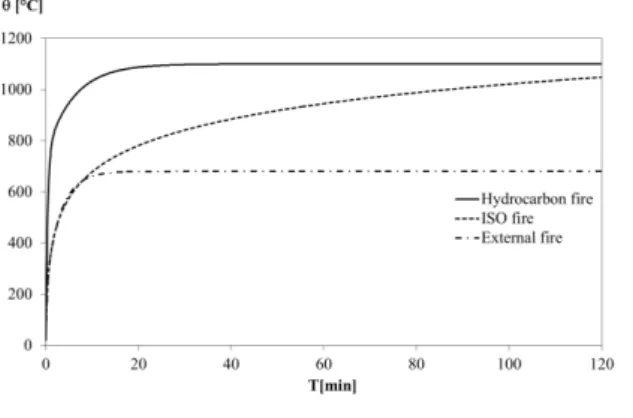
The Standard temperature-time curve ISO 834 [4], also known as the Cellulosic curve and/or the standard nominal fire curve, is used as test method for determining the fire resistance of various elements of construction when subjected to standard fire exposure conditions. The test data thus obtained will permit subsequent classification on the basis of the duration for which the performance of the tested elements under these conditions satisfies specified criteria.
In 1981, Margaret Law [16] presented a paper at the ASCE Spring Convention in New York entitled “Designing fire safety for steel –recent work”, the visionary paper presented a summary of novel work that she and her colleagues at Arup Fire had completed to evaluate the structural fire safety of innovative and architecturally exciting buildings – such as the Pompidou Centre in Paris. Among the many topics covered in this paper, stated a number of criticisms of the standard fire resistance test and proposed the way forward using knowledge-based analytical approaches.
The standard temperature-time curve is not representative of a real fire in a real building. Indeed it is physically unrealistic and actually contradicts knowledge from fire dynamics. The standard temperature-time curve is given according to next expression.
g 20345log108t1 C (1)
Where g is the gas temperature in the fire compartment [°C], t is the time [min], assuming the coefficient of heat transfer by convection equal to c 25
W/m2K
1 0,687. 0,675.
C .660
20 0,32. 0,38.
t t
g e e
(2)Where g is the gas temperature in the fire compartment [°C], t is the time [min] and the coefficient of heat transfer by convection is consider equal toc 25
W /m2K
The hydrocarbon is a nominal temperature-time curve used in case where storage of hydrocarbon materials makes fires extremely severe, the hydrocarbon temperature-time curve is given by:
1 0,325. 0,675.
C .1080
20 0,167. 2,5.
t t
g e e
(3)Where g is the gas temperature in the fire compartment [°C], t is the time [min] and the coefficient of heat transfer by convection is consider equal to c
W m K
2 / 50
Fig. 3 represents the variation of the gas temperature versus time for the nominal fire curves.
. Fig. 3 - Nominal fire curves.
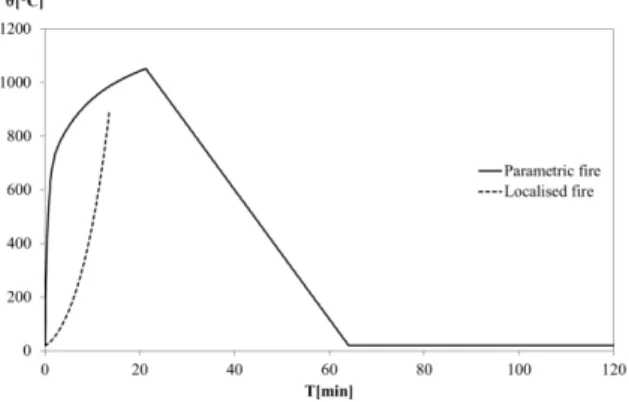
2-1-2- Natural fire curves
localized fire can be assessed using the method Heskestad. Localized fire temperature-time curve may be calculated according to:
530 3 2 25 , 0
20
Qc z z
z
(4)
Where z is the temperature of the plume along the vertical flame axis [°C],
Q
cis the convective part of the heat release rate [W], z is the height along the flame axis and z0 is the virtual origin of the fire, see Fig. 4.
Fig. 4 - Parameters of localized fire.
The gas temperature representing the fire can also be given by the parametric temperature–time curve model given from annex A of EN 1991-1-2 [17]. This annex presents all equations required to calculate the temperature–time curve based on the value of the parameters that describe the particular situation. The model is valid for fire compartments up to 500 m2 of floor area, maximum height of 4 meters without openings in the roof.
Parametric fires provide a simple means to take significant account physical phenomena that can influence the development of a fire in a particular building. As nominal fires, they provide a temperature-time curve, but these curves include some parameters intended to represent some real aspects in fire compartment. These curves have a heating and a cooling phase. The heating and cooling phase can be defined by the next equations.
) 472 . 0 204 . 0 324 . 0 1 .( 1325
20 0,2t* 1,7t* 19t*
g e e e
* *max
max 250t t
g
(6)Where g is the gas temperature in the fire compartment [°C], t is the time [min];
*
t is the time parameter that depends on the time factor, which itself depends on the opening factor and on the thermal absorptivity.
Fig. 5 represents the variation of temperature versus time for natural fire curves.
Fig. 5 - Natural fire curves.
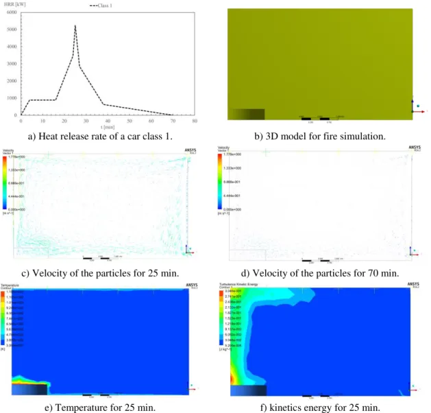
EN 1991-1-2 [17] allows the utilisation of CFD (Computational Fluid Dynamics) models. Although EN 1991-1-2 [17] states under Clause 3.3.2 (2) that a method is given in Annex D for the calculation of thermal actions in case of CFD models, this annex simply gives general principles that form the base of the method and must be respected when establishing a software that allows application of this method in order to estimate the temperature field in the compartment. No guidance is provided on the manner to deduce the heat flux on the surface of the structural elements from the temperatures calculated in the compartment by the CFD model. In fact, this topic is still nowadays a subject of ongoing research activities and is probably premature to layout recommendations in a Code. The Eurocode allows the application of the CFD models in fire safety engineering but, this only can be made by well experienced user. Computational Fluid Dynamics (CFD) may be used to analyse fires in general, solving the Navier-Stokes equations, energy equation, and continuity equation, with special models for turbulence and radiation models. The equation for species can also be activated if the fire source is well established.
compartment assumes the use of symmetry boundary conditions, allowing to model only one quarter of the full compartment. This compartment has two openings on the left side and right side, a concrete slab on the bottom and top floor and a concrete wall in the front and rear façade. The thermal load is defined by the Heat Released Rate. Three types of boundary conditions were applied (fixed wall with thermal conduction through thickness, pressure out let and symmetry). The solution method monitors the residuals for all variables and assumes the convergence of the solution for continuity (residual less than 0,01), velocity components (residual less than 0,001), energy (residual less than 0,00001), turbulence parameters (residual less than 0,001) and radiation parameters (residual less than 0,000001).
a) Heat release rate of a car class 1. b) 3D model for fire simulation.
c) Velocity of the particles for 25 min. d) Velocity of the particles for 70 min.
2-2- Heat transfer
The modes of heat transfer are defined in Eurocode EN 1991-1-2 [17]. The net
heat flux to unit surface area
2
m Whnet is going to be defined on the surface of the element. All surfaces exposed to fire must assume the transfer of heat by convection and radiation, given by the following expression.
2
, ,
, h h W m
hnetd netc netr (7)
The convection heat transfer is the energy that is transferred between a solid and a moving fluid or gas, each being at different temperatures. The rate at which this exchange of energy occurs is given by Newton's law of cooling, shown Eq.(8).
2
, W m
hnetc c g m (8)
Where, cIs the heat transfer coefficient by convection
W m2K
, gis the gastemperature in the vicinity of the fire exposed member
º
C
, and
m is the surfacetemperature of the member
º
C
.The convection coefficient value depends on the velocity of the fluid or gas and should be considered equal to 9, 25 and 50 for cases of non-exposed surface, exposed surface with ISO834 curve [4]and exposed surface with hydrocarbons.
The heat transfer by radiation represents the energy transfer between two bodies through electromagnetic waves. This form of energy transfer is exhibit by all bodies, and requires no medium for the heat to be transferred. It can even occur in a vacuum the amount of energy that can be radiated by a surface is given by the Stefen-Boltzmann law shown in Eq.(9) .
4 4
2
, 273 273 W m
hnetr f m r m (9)
Where represents the view factor; f represents the emissivity of the fire;
m
2 4
8 10 67 ,
5 W m K ;
rrepresents is the effective radiation temperature of the fire environment
º
C
;
m represents the surface temperature of the member
º
C
.The emissivity of the material for steel and concrete is equal tom 0,7. The emissivity of the fire (flames) is assumed f 1,0 and the view factor can be assumed equal to 1,0 when not specified.
2-3- Materials properties
2-3-1- Thermal properties
2-3-1-1- Steel profile and reinforcing
The Specific heat of steel represents the amount of energy that is necessary to
raise the unit mass of steel temperature by
1
C
, it is also the measure of the materialsability to absorb heat. The specific heat of steel Ca defined in accordance to Eurocode EN1993-1-2 [18] as the following:
600
: 20C C
J/kg.k
10
.
22
,
2
10
.
69
,
1
10
.
73
,
7
425
1 a 3 a2 6 a3a
C
(10)
735
: 600C C
J/kg.k
738 13002 666 a a C (11)
900
: 735C C
J/kg.k
731 17820 545 a a C (12)
1200
: 900C C
C
a
650
J/kg.k
(13)
Fig. 7 - Specific heat at elevated temperature.
Thermal conductivity is the coefficient which dictates the rate which heat arriving at the steel surface is conducted through the metal. According to Eurocode EN1993-1-2 [18] the variation of thermal conductivity with temperature is represented in Fig. 8. The thermal conductivity of steel a should be determined from the following:
800
: 20C C
w/mk
10
.
33
,
3
54
2 aa
(14)
1200
: 800C C
a
27
,
3
w/mk
(15)Fig. 8 - Thermal conductivity at elevated temperature
Fig. 9 - Density of steel at elevated temperature
2-3-1-2- Concrete
The specific heat of concrete varies mainly with the moisture content. The
moisture within the concrete causes a peak between
100
C
and
200
C
due to thewater being driven off. Fig. 10 depicts the variation of this property with temperature The pick value depends on the amount of moisture, in this case u3% was assumed, The Eurocode EN 1992-1-2 [19] recommends the following relationship for calculation of concrete specific heat.
100
: 20C C
900P
C (16)
115
: 100C C
2020P
C (17)
200
: 115C CCP
2020
115
/12 (18)
400
: 200C CCP
1000
200
/2 (19)
1200
: 400C CFig. 10 - Specific heat at elevated temperature.
The thermal conductivity depends upon the aggregate type and the temperature of the concrete. The thermal conductivity λc of concrete may be determined between lower and upper limit values. Fig. 11 represent the variation of the upper limit of thermal conductivity with temperature. The following equation defined in Eurocode EN 1992-1-2 [19] recommends the upper limit for normal weight concrete.
2 0.2451
/100
0.0107
/100
2
w/mk
c (21)
Fig. 11 - Thermal conductivity at elevated temperature.
Density is a physical property of matter. In a qualitative manner density is defined as the heaviness of objects with a specific volume. It is denoted as ρ. Common unit of density is kg/m3. Fig. 12 represents the variation of density with temperature. We have CKg/m3, The Eurocode EN 1992-1-2 [19] recommends the following relationship for calculation of concrete density.
115
: 20C C
20C
(22)
200
: 115C C
20C
.
10,02
115
/85
(23)
400
:200C C
20C
.
0,980,03
200
/200
(24)
1200
:400C C
20C
.
0,950,07
400
/800
(25)
Fig. 12 - Density of concrete at elevated temperature.
2-3-2- Mechanical properties
2-3-2-1- Steel profile S275
The nominal resistance of steel profiles is characterized in European standards Eurocode EN1993-1-1 [2] for room temperature and Eurocode EN1993-1-2 [18] for elevated temperatures (the action of fire). The values of the yield and ultimate stress, fy
and
f
u, are defined in this document. Under normal conditions the S275 steel, withthickness less than 40mm, presents the mechanical properties described in Table 3 and Fig. 13 shows the variation of the stress-strain relationship at different temperature levels.
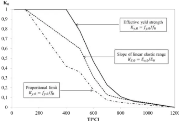
The reduction factors for the proportional limitkp,, to the effective yield strength ky,
and to the slope of the linear elastic range kE, are provided in Fig. 14. The stress-strain
relationship for steel at elevated temperatures is represented in Table 4.
Table 3 - Mechanical characteristics of steel S275.
GPa
E
af
y
MPa
f
u
MPa
G
a
GPa
210 275 430 81 0,3
Table 4 - Stress-strain relationship for steel at elevated temperatures.
Strain range Stress Tangent modulus
p,
E
a,E
a,
p,
y,
5 . 0 2 , 2
, / y
p c b a a
f
2
0.5, 2 , y y a a b
y,
t,f
y, 0
t,
u,f
y,
1
t,
/
u,
t,
-
u, 0,00 -Parameters
p,
f
p,/
E
a,
y,
0
,
02
t,
0
,
15
u,
0
,
20
Functions
, , , , , 2 / a p y py c E
a
2, , , 2 c E c
b
y
p a
, , , , , 2 , ,2 y p
a p y p y f f E f f c
2-3-2-2- Concrete C20 / 25
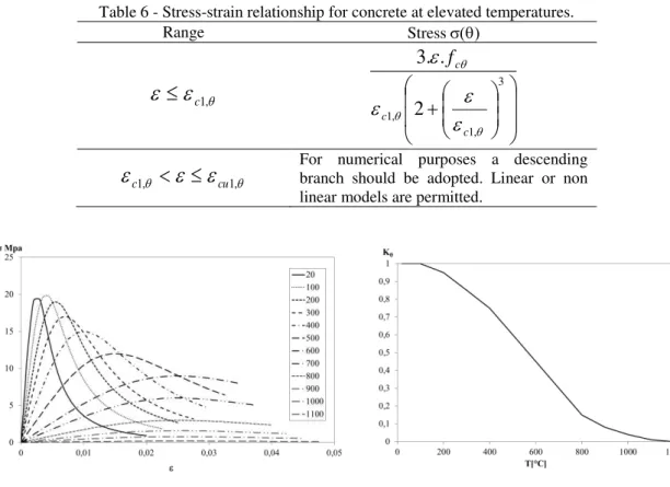
The concrete strength at room temperature is defined in Eurocode EN 1992-1-1 [20]. Eurocode EN1992-1-2 [19] is the reference document for this material under fire conditions.The material properties of concrete C20 / 25 at room temperature are shown in Table 5 the stress-strain relationship for concrete at elevated temperatures is illustrated in Table 6 and Fig. 15 showing the expected nonlinear variation.
The reduction of the characteristic compressive strength of concrete with the
variation of the temperature Τ is allowed by the coefficient
k
c,t , this coefficient isrepresented in Fig. 16.
Table 5 - Mechanical characteristics of the concrete C20 / 25
MPa
f
ckf
ck,cube
MPa
f
cm
MPa
f
ctm
MPa
E
cm
GPa
c1
000
cu1
00020 25 28 2,2 30 2,0 3,5
Table 6represents Stress-strain relationship for concrete at elevated temperatures.
Table 6 - Stress-strain relationship for concrete at elevated temperatures.
Range Stress
c1, 3 , 1 , 1 2 . . 3 c c c f
c1,
cu1, For numerical purposes a descending branch should be adopted. Linear or non linear models are permitted.
Fig. 15 - Curve stress-strain of concrete under compression.
2-4-2-3- Reinforcing steel S500
The characteristics of the steel reinforcement is described in Eurocode EN 1992-1-1 [20]. Steel S500 NR, class B has the properties described in Table 7.
When subjected to high temperatures, Eurocode EN 1992-1-2 [19] defines reduction factors to be applied to the mechanical properties. The value of the yield stress fsy,, the value of proportional limit fsp, and the value of the modulus of
elasticity Es, varies with temperature as can be seen in Fig. 18 the factors are
represented to reduce the effective yield strength, and the modulus of elasticity. The stress-strain relationship for reinforcement at elevated temperatures is defined by Table 8, and Fig. 17 represents the curve variation of stress-strain.
Table 7 - Mechanical characteristics of steel S500.
GPa
E
sf
yk
MPa
f
uk
MPa
G
GPa
k
210 500 540 81 1,08 0,3
Table 8 - Stress-strain relationship for reinforcement at elevated temperatures.
Strain range Stress Tangent modulus
sp,
E
s,E
s,
sp,
sy,
2
0.5 ,2
, / sy
sp c b a a
f
2
0.5, 2 , sy sy a a b
sy,
st,f
sy, 0
st,
su,f
sy,
1
st,
/
su,
st,
-
su, 0,00 -Parameters
sp,
f
sp,/
E
s,
sy,
0
,
02
st,
0
,
15
su,
0
,
20
Functions
, , , , , 2 / s sp sy spsy c E
a
2, , , 2 c E c
b
sy
sp s
, , , , , 2 , ,Fig. 17 - Curve stress-strain of reinforcement under tension.
CHAPTER.3 SIMPLIFIED METHOD USING EUROCODE 4-ANNEX G
Eurocode 4 part 1-2 [1] proposes different methods to determine the fire resistance of Partially Encased Columns under standard fire ISO834 [4]. The tabulated method uses values defined for the most common cross-sections based on experimental and empirical results. These results are generally very conservative and may be used for a preliminary design stage [21].
The simplified calculation method was originally developed Jungbluth [22] and was defined to determine the capacity of the PEC by dividing the section into four components. The current approach of this method is defined in Eurocode 4 part 1.2 [1] and is based on simple formulas and empirical coefficients that seem to be unsafe [23]. For this purpose, a new simple formulae was presented and is being validated [24].
The stability of PEC requires the calculation of the critical load and the effective flexural stiffness. These quantities depend on the temperature effect on the elastic modulus and on the second order moment of area of each component, according to Eq.(26).
EI
fi,eff,z
f,
EI
fi,f,z
w,
EI
fi,w,z
c,
EI
fi,c,z
s,
EI
fi,s,z (26)In this equation EI fi,eff,z represents the effective flexural stiffness of the
composite section in fire, EI fi,f,z represents effective flexural stiffness of the flange,
EI fi,w,z represents effective flexural stiffness of the web, EI fi,c,z represents the
effective flexural stiffness of the concrete and EI fi,s,z represents the effective flexural
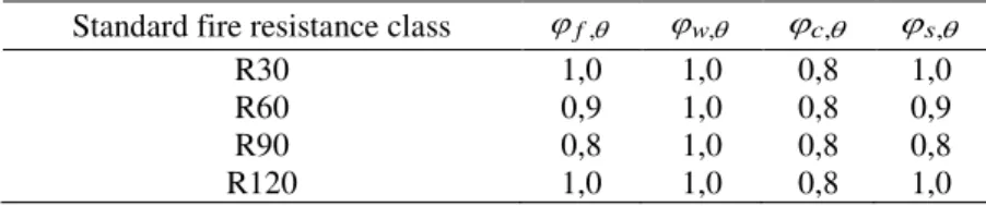
stiffness of reinforcement. The contribution of each part is going to be weighted according to factors, a reduced modulus of elasticity and a reduced cross-section. These values depend on the fire rating, according to Table 9.
Table 9 - Reduction coefficients for bending stiffness around the week axis. Standard fire resistance class f, w, c, s,
R30 1,0 1,0 0,8 1,0
R60 0,9 1,0 0,8 0,9
R90 0,8 1,0 0,8 0,8
The elastic buckling load Nfi,cr,z requires the calculation of the effective flexural
stiffness of the composite section in fire EI fi,eff,z. The non-dimensional slenderness
ratio and Nfi,cr,z are calculated according to Eqs.(27 -(29), when the safety partial
factors are assumed equal to 1.0. The buckling length of the column under fire conditions is represented byL. The calculation of the axial plastic resistance under fire
Rd pl fi
N , , the cross-section is divided into four components according to Eq.(27).
s Rd pl fi c Rd pl fi w Rd pl fi f Rd pl fi Rd pl
fi
N
N
N
N
N
, ,
, , ,
, , ,
, , ,
, , , (27)z cr fi Rd pl fi N
N , , , ,
(28)
fieff z zcr
fi L EI
N , ,
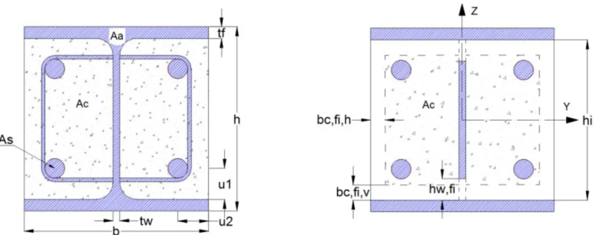
2 2 , , (29)This calculation method takes into consideration the effect of the fire in four components of the cross section. The four components are identified in Fig. 19 and include: the flange component, the web component, the concrete and reinforcement components.
Fig. 19- Reduced cross-section for structural fire design.
3-1- Definition of partially encased column
compared to the same section of the steel profile, the formwork and the connection with the beam is easily when compared with the solution of totally encased column. In addition to these advantages, the reinforced concrete is responsible for increasing the fire resistance.
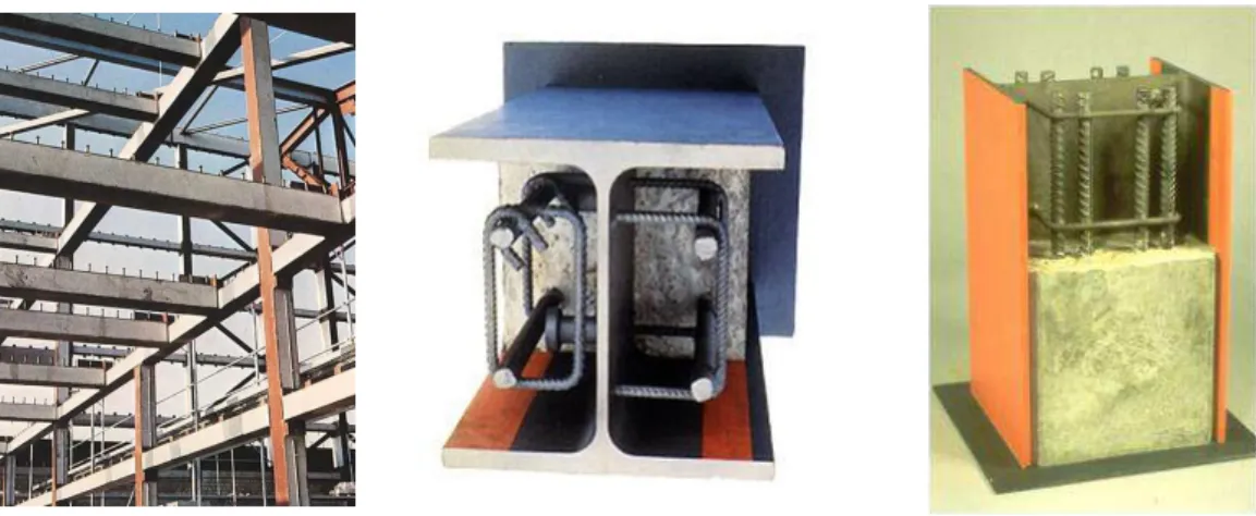
Fig. 20 - Example of partially encased column.
Twenty-four different cross sections were selected to analyse the effect of fire: ten steel IPE profiles ranging from 200 to 500 and fourteen steel HEB ranging from 160 to 500. These columns were tested under standard fire ISO834 [4], using three buckling length explained in Fig. 21 , using 3m and 5m column height. S275 and B500 grades were selected to steel while C20/25 grade was considered to concrete.
a) Buckling deformed shape b) Buckling length in fire c) Finite element approximation Fig. 21 - Partially encased column under fire.
Table 10 presents the main dimensions of the cross section, in particular the number of rebars, the diameter of each rebar, the cover dimensions in both principal directions.
Table 10 - Characteristics of the sections under study.
profile Nº of rebars
mm
sA
2mm
c
A
2mm
1
u
mm
2
u
mm
u
mm
s cs A A A f w t
t
A
mV
1
mm
HEB160 4 12 452 19916 40 40 40 2,22 0,62 3,61
HEB180 4 12 452 25616 40 40 40 1,74 0,61 2,86
HEB200 4 20 1257 31213 50 50 50 3,87 0,60 6,45
HEB220 4 25 1963 37611 50 50 50 4,96 0,59 8,36
HEB240 4 25 1963 45417 50 50 50 4,14 0,59 7,05
HEB260 4 32 3217 53033 50 50 50 5,72 0,57 10,01
HEB280 4 32 3217 62541 50 50 50 4,89 0,58 8,39
HEB300 4 32 3217 72501 50 50 50 4,25 0,58 7,34
HEB320 4 32 3217 77275 50 50 50 4,00 0,56 7,12
HEB340 4 40 5027 80509 50 50 50 5,88 0,56 10,53
HEB360 4 40 5027 85536 50 50 50 5,55 0,56 9,99
HEB400 4 40 5027 95821 70 50 59 4,98 0,56 8,86
HEB450 4 40 5027 108801 70 50 59 4,42 0,54 8,20
HEB500 4 40 5027 121735 70 50 59 3,97 0,52 7,66
IPE200 4 12 452 16823 50 40 45 2,62 0,66 3,97
IPE220 4 20 1257 19730 50 40 45 5,99 0,64 9,34
IPE240 4 20 1257 23825 50 40 45 5,01 0,63 7,92
IPE270 4 25 1963 30085 50 40 45 6,13 0,65 9,47
IPE300 4 25 1963 37848 50 40 45 4,93 0,66 7,43
IPE330 4 25 1963 44854 50 40 45 4,19 0,65 6,43
IPE360 4 32 3217 50988 50 40 45 5,93 0,63 9,42
IPE400 4 32 3217 60715 70 40 53 5,03 0,64 7,90
IPE450 4 32 3217 72779 70 40 53 4,23 0,64 6,57