Lussac Prestes Maia
Environmental model-based time-reversal
underwater communications
University of Algarve
Faculty of Sciences and Technology 2017
Lussac Prestes Maia
Environmental model-based time-reversal
underwater communications
PhD. Thesis in Electronics and Telecomunications (Signal Processing)
Developed under supervision of:
Prof. Doutor S´
ergio Manuel Machado Jesus
Prof. Doutor Ant´
onio Jo˜
ao Freitas Gomes da Silva
University of Algarve
Faculty of Sciences and Technology 2017
Environmental model-based time-reversal
underwater communications
Declara¸c˜ao de autoria do trabalho
Declaro ser o autor deste trabalho, que ´e original e in´edito. Autores e trabalhos consultados est˜ao devidamente citados no texto e constam da listagem de referˆencias bibliogr´aficas inclu´ıda.
Copyright ©Lussac Prestes Maia
A Universidade do Algarve tem o direito, perp´etuo e sem limites geogr´aficos, de arquivar e publicitar este trabalho atrav´es de exemplares impressos repro-duzidos em papel ou de forma digital, ou por qualquer outro meio conhecido ou que venha a ser inventado, de o divulgar atrav´es de reposit´orios cient´ıficos e de admitir a sua c´opia e distribui¸c˜ao com objectivos educacionais ou de investiga¸c˜ao, n˜ao comerciais, desde que seja dado cr´edito ao autor e editor.
`
A querida Jorgia Ao meu filho Theo &
i
Acknowledgements
I would like to thank all those who somehow helped me to get this research work done. In particular I acknowledge for the contributions of my supervisors Prof. S´ergio and Prof. Ant´onio. The discussions I had with them over these four years in the UAlg generated valuable advise and guidance, which contributed to my effort to better understand the most important issues of ocean acoustic propagation in the scope of digital communica-tions. Their large experience both in academic subjects as well as in operational tasks at sea helped me to develop this research work. Thank you.
Thanks to my colleagues of the Signal Processing Laboratory, members and ex-members, for your friendship and good talks: Nelson Martins, Ana Bela, Rog´erio Calazans, Dymtro Maslov, Agni Mantouka, Cristiano Soares, Friedrich Zabel, Paulo Santos, Orlando Ro-driguez e Paulo Felisberto. It was great to have been part of the SiPLAB team.
I would like to thank my designation for this course to the Brazilian Navy, whose current commander is the Admiral Eduardo Bacellar Leal Ferreira. I am honored by the trust placed in me to carry out this challenging course.
Thanks to my parents, D´ecio (in memoriam) and Terezinha, for the love and tireless effort to give me and my brothers a happy life. The family structure that you gave me helped me a lot to overcome my obstacles.
Heartfelt thanks to my wife Jorgia and son Theo. Thank you for the tremendous sup-port, love and patience to accept my absence to devote myself intensely to the studies. You made me strong to overcome all the difficulties and to struggle for my goals. Finally, thank God for this valuable opportunity in my professional life.
This work was funded by the Postgraduate Study Abroad Program of the Brazilian Navy, P.C.Ext., Port.219-09/13/EMA and Port.386/MB-07/13.
iii
Name: Lussac Prestes Maia
College: Faculty of Sciences and Technology University: University of Algarve
Supervisors: S´ergio Manuel Machado Jesus, Professor at Faculty of Sciences and Technology, University of Algarve
Ant´onio Jo˜ao Freitas Gomes da Silva, Associate Professor at Engineer-ing Institute, University of Algarve
Thesis title: Environmental model-based time-reversal underwater communications
Abstract
Advances in underwater acoustic communications require the development of methods to accurately compensate channels that are prone to severe double spreading of time-varying multipath propagation, fading and signal phase variations. Assuming the environmen-tal information as a key issue, this work aims to improve communications performance of single-input-multiple-output transmission systems in such channels through the en-hancement of their estimates used for equalization. The acoustic propagation physical parameters of the environment between the source and the receivers are considered in the process. The approach is to mitigate noise effects in channel identification for Pas-sive Time-Reversal (PTR), which is a low complexity probe-based refocusing technique to reduce time spreading and inter-symbol interference. The method Environmental-based PTR (EPTR) is proposed that, inspired by matched field inversion, inserts physics of acoustic propagation in the channel compensation procedure through ray trace modeling and environmental focalization processing. The focalization is the process of tweaking the environmental parameters to obtain a noise-free numerical model generated channel response that best matches the observed data. The EPTR performance is tested and compared to the pulse-compressed PTR and to the regularized `1-norm PTR. The former is based on classical `2-norm channel estimation and the latter, inspired by compressive sensing, uses weighted `1-norm into the `2-norm estimation problem to obtain improved estimates of sparse channels. Successful experimental results were obtained with the pro-posed method for signals containing image messages transmitted at 4 kbit/s from a source to a 16-hydrophones vertical array at 890 m range during the UAN’11 experiment con-ducted off the coast of Trondheim (Norway). The scientific contributions of this work are (i) the understanding of the process of employing physical modeling and environmental focalization to equalize and retrieve received messages in underwater acoustic communi-cations, thus exploiting the sensitivity of environmental parameters in order to adapt a communications system to the scenario where it is used; and (ii) the presentation of a new PTR-based method that focuses environmental parameters to model suitable noise-free channel responses for equalization and whose real data results were successful for a set of coherent signals collected at sea. The proposed method is a step forward to a better understanding on how to insert physical knowledge of the environment for equalization in digital underwater acoustic communications.
Keywords: Underwater acoustic communications, passive time reversal, equalization, coherent communications, physical modelling, environmental focalization.
v
Nome: Lussac Prestes Maia
Faculdade: Faculdade de Ciˆencias e Tecnologia Universidade: Universidade do Algarve
Orientadores: S´ergio Manuel Machado Jesus, Professor Catedr´atico da Faculdade de Ciˆencias e Tecnologia, Universidade do Algarve
Ant´onio Jo˜ao Freitas Gomes da Silva, Professor Adjunto do Instituto Superior de Engenharia, Universidade do Algarve
T´ıtulo da Tese: Comunica¸c˜oes submarinas de tempo-reverso baseada em modelo do ambiente
Resumo
Nos ´ultimos anos, as aplica¸c˜oes em comunica¸c˜oes ac´usticas submarinas, como ob-servat´orios oceˆanicos, ve´ıculos submarinos aut´onomos e controle remoto na ind´ustria de petr´oleo offshore, entre outros, tˆem despertado o interesse da comunidade cient´ıfica. Avan¸cos nessa ´area requerem o desenvolvimento de m´etodos que visam compensar os efeitos de distors˜ao produzidos pelo canal de transmiss˜ao submarino no sinal recebido. Essa distors˜ao ´e tanto mais importante quanto o cen´ario de comunica¸c˜oes comporta uma zona de ´aguas pouco profundas, com alcance fonte-receptor de alguns quil´ometros e cerca de cem metros de profundidade, os quais s˜ao propensos a um severo espalhamento duplo em tempo-frequˆencia devido a propaga¸c˜ao de m´ultiplos caminhos vari´avel no tempo, desvanecimento e varia¸c˜oes de fase do sinal. A compensa¸c˜ao dessas distor¸c˜oes ´e necess´aria para realizar comunica¸c˜oes submarinas com taxas de transmiss˜ao de, e.g., mais de 2 kbit/s. Este trabalho tem como objetivos: investigar a influˆencia dos parˆametros f´ısicos da propaga¸c˜ao ac´ustica em comunica¸c˜oes submarinas coerentes de alta frequˆencia (∼10kHz-30kHz) em ´aguas pouco profundas, para usar esse conhecimento em prol da melhoria de performance de comunica¸c˜oes com base em modelos f´ısicos e focaliza¸c˜ao ambiental ou “Environmental Focalization” (EF); e projetar um recetor de tempo-reverso baseado em EF cujo desempenho de equaliza¸c˜ao com dados reais possa ser superior ao desempenho de um recetor padr˜ao de tempo-reverso.
A abordagem ´e a de mitigar os efeitos do ru´ıdo na identifica¸c˜ao do canal para o proces-sador Passivo de Tempo-Reverso (PTR), que ´e uma t´ecnica de baixa complexidade de retro-focagem para reduzir a dispers˜ao no tempo e a interferˆencia entre s´ımbolos. Para isso, ´e proposto o m´etodo PTR baseado em modelos do ambiente ou “Environmental-based Passive Time-Reversal” (EPTR), o qual usa EF, inspirado em processamento por ajuste de campo ou “Matched Field Processing” (MFP), e insere um modelo de propaga¸c˜ao ac´ustica sem ru´ıdo no processo para a compensa¸c˜ao do canal, esperando com isso eliminar os efeitos de ru´ıdo nas estimativas ligando assim o ambiente `a resposta do canal. A EF ´e o processo de ajuste dos parˆametros ambientais para obter uma resposta de canal baseada em modelo num´erico sem ru´ıdo que melhor corresponda aos dados observados. O m´etodo proposto tem um car´acter inovador no sentido em que a modelos fisicos, tanto quanto nos ´e dado saber, n˜ao tˆem sido utilizados em comunica¸c˜oes submarinas.
A influˆencia dos parˆametros f´ısicos de propaga¸c˜ao ac´ustica para modelar r´eplicas do canal de comunica¸c˜oes submarinas tem um papel importante na sele¸c˜ao do espa¸co de busca “a priori”, uma vez que alguns parˆametros f´ısicos s˜ao mais influentes na propaga¸c˜ao e portanto tˆem maior efeito sobre as r´eplicas modeladas. Assim, testes simulados de sensibilidade dos
vi
parˆametros f´ısicos na frequˆencia de 14 kHz foram realizados antes do processamento com dados reais. Embora na faixa de baixa frequˆencia (< 2 kHz) a influˆencia dos parˆametros j´a seja bem conhecida na literatura, os efeitos desses parˆametros na ac´ustica oceˆanica em banda de frequˆencia usual de comunica¸c˜oes como, por exemplo, na banda de 10kHz-30kHz, n˜ao est˜ao bem documentados. Espera-se com estas simula¸c˜oes obter informa¸c˜oes sobre os efeitos da distor¸c˜ao de parˆametros geom´etricos e geoac´usticos, contribuindo para projetar um processador que empregue um procedimento de focagem baseado no modelo do ambiente onde o sistema seja usado.
O uso de um modelo f´ısico livre de ru´ıdo provou ser bem sucedido para resolver problemas de MFP com frequˆencia dos sinais usualmente abaixo de 2 kHz como, por exemplo, localiza¸c˜ao de fontes. Essencialmente, o MFP compara, usando alguma fun¸c˜ao objetivo, um campo medido com o conjunto de campos ac´usticos modelados e seleciona a r´eplica modelada sem ru´ıdo com melhor ajuste. Inspirado pelo sucesso do procedimento utilizado em MFP e considerando que as estimativas da resposta impulsiva do canal (CIR) sem ru´ıdo podem evitar uma degrada¸c˜ao severa do desempenho do PTR, o autor foi motivado a projetar o EPTR que, apesar de usar banda de alta frequˆencia (uma frequˆencia de portador de 25,6 kHz foi usada neste trabalho), produziu resultados experimentais bem-sucedidos atrav´es da focaliza¸c˜ao de um espa¸co de busca de parˆametros f´ısicos “a priori”. A focaliza¸c˜ao gera como sa´ıda uma r´eplica de resposta impulsiva “a posteriori” sem ru´ıdo com melhor aptid˜ao na sua fun¸c˜ao objetivo. Um processador linear, que correlaciona as r´eplicas modeladas com uma estimativa de resposta impulsiva, foi usado como fun¸c˜ao objetivo. Assim, o erro na identifica¸c˜ao da CIR causada pelo ru´ıdo ´e substitu´ıdo por algum erro de modela¸c˜ao, que dever´a ser suficientemente pequeno quando a focaliza¸c˜ao ambiental for bem-sucedida, melhorando o desempenho das comunica¸c˜oes.
As simula¸c˜oes, usando uma frequˆencia de portadora de 14 kHz, mostraram que os efeitos do sub-fundo tendem a ser negligenci´aveis devido `a severa atenua¸c˜ao , sendo apenas importante a camada superior de sedimentos. Al´em disso, a velocidade compressional do som nos sedimentos afeta a CIR tanto no espalhamento no tempo como na posi¸c˜ao das chegadas, o que ´e uma caracter´ıstica importante a considerar para escolher candidatos ao espa¸co de busca “a priori” para focaliza¸c˜ao, dado que para a compensa¸c˜ao do canal a precis˜ao no tempo de atraso de chegada ´e mais importante do que a amplitude de chegada. O perfil de velocidade do som (SSP) ´e um parˆametro importante na propaga¸c˜ao ac´ustica, por isso ´e recomend´avel uma medi¸c˜ao in situ com equipamento “Conductivity, Temperature, and Pressure” (CTD) para que as r´eplicas candidatas no espa¸co de busca sejam baseadas em simula¸c˜oes o mais real´ısticas poss´ıveis e possibilitem ao m´etodo EF gerar um modelo equivalente adequado, i.e., um modelo em que embora os parˆametros f´ısicos n˜ao correspondam inteiramente ao parˆametros reais, a compensa¸c˜ao entre parˆametros simulados produza uma CIR que seja pr´oxima `a resposta real do canal. Os parˆametros geom´etricos (i.e., a distˆancia fonte-recetores e as suas profundidades) s˜ao em princ´ıpio os mais importantes, uma vez que causam distor¸c˜ao Doppler severa, muito embora a distor¸c˜ao possa ser significativamente reduzida ao empregar sensores ancorados e t´ecnicas de reamostragem. Para a focaliza¸c˜ao ambiental, os efeitos devidos ao pequeno comprimento de onda sugerem o uso de alta resolu¸c˜ao no espa¸co de busca de parˆametros; a baixa influˆencia dos parˆametros do sub-fundo sugere exclu´ı-los da otimiza¸c˜ao, economizando assim custo computacional sem perda significativa de desempenho de comunica¸c˜oes; e, os efeitos da velocidade compressional do som nos sedimentos sugerem aumentar a amostragem do espa¸co de busca deste parˆametro, visando explorar a caracter´ıstica de mudan¸cas no tempo
vii de atraso de chegada nos picos da CIR.
Os dados reais modulados digitalmente por comuta¸c˜ao-de-fase-em-quadratura (QPSK) recolhidos na experiˆencia de mar “Underwater Acoustic Network’11” realizada em maio de 2011 na costa de Trondheim (Noruega) s˜ao utilizados para testar a performance do m´etodo de equaliza¸c˜ao proposto. V´arias mensagens moduladas contendo uma imagem de baixa resolu¸c˜ao foram transmitidas a 4 kbit/s entre um modem ac´ustico fundeado e uma antena vertical de 16 hidrofones fundeada a uma distˆancia de 890 metros. Os dados s˜ao processados com o m´etodo EPTR, sendo ent˜ao comparadas aos m´etodos PC-PTR padr˜ao e ao RegL1-PTR para an´alise de performance. Os resultados experimentais mostram que o m´etodo proposto supera o PTR padr˜ao, produzindo um ganho robusto (de um total de dez mensagens de 100 mil bits cada, coletadas entre 24 de maio e 27 de maio, sete produziram ganho), em erro quadr´atico m´edio. Comparando os desempenhos, o RegL1-PTR mostrou ser o mais est´avel e efetivo em geral, uma vez que apresentou os maiores ganhos e em todas as mensagens analisadas superou a performance do PC-PTR padr˜ao. O EPTR apresentou os segundos maiores ganhos e em setenta porcento das mensagens analisadas superou a performance do PC-PTR. Em trinta porcento das mensagens o EPTR superou inclusive a performance do RegL1-PTR, gerando o melhor desempenho.
As contribui¸c˜oes cient´ıficas deste trabalho s˜ao: (i) a compreens˜ao obtida no processo de empregar modelos f´ısicos e focaliza¸c˜ao ambiental para equaliza¸c˜ao e recupera¸c˜ao de mensagens recebidas em comunica¸c˜oes ac´usticas submarinas, explorando a sensibilidade dos parˆametros ambientais para adaptar um sistema de comunica¸c˜ao ao cen´ario onde ´e usado; e (ii) a apresenta¸c˜ao de um novo m´etodo baseado em PTR que otimiza os parˆametros ambientais para modelar respostas adequadas de canais sem ru´ıdo para equaliza¸c˜ao, cujos resultados usando dados reais foram bem sucedidos para um conjunto de sinais coerentes coletados em experimento no mar. O m´etodo proposto contribui para um avan¸co no sentido de incorporar o conhecimento f´ısico do meio ambiente no processamento para equaliza¸c˜ao em comunica¸c˜oes digitais ac´ustico submarina.
Palavras-chave: Comunica¸c˜oes submarinas, processamento de tempo-reverso, equaliza¸c˜ao, comunica¸c˜oes coerentes, modelos f´ısicos de propaga¸c˜ao, focaliza¸c˜ao ambiental.
Contents
Acknowledgements i
Abstract v
Resumo vii
List of Acronyms xi
List of Figures xiii
List of Tables xix
1 Introduction 1
1.1 Underwater communications and equalization . . . 1
1.2 State of the Art . . . 7
1.2.1 Short historical underwater communication review . . . 8
1.2.2 Adaptive equalizers . . . 9
1.2.3 Time-reversal processors . . . 11
1.2.4 Environmental focalization and equivalent model . . . 14
1.3 Motivation . . . 16
1.3.1 Promissory perspective . . . 18
1.3.2 Objectives . . . 19
1.4 Thesis outline . . . 19
2 Methodology and data model 21 2.1 Methodology . . . 21
2.2 Communication system data model . . . 23
2.3 Passive time reversal . . . 26
2.4 Pulse-compression channel estimation . . . 29
2.5 Regularized `1-norm channel estimation . . . 30
2.6 Environmental focalization channel estimation . . . 33
2.7 The Environmental-based Passive Time-Reversal . . . 36
3 Physical parameters sensitivity in simulated underwater communications 39 3.1 Shallow water acoustic propagation . . . 39
3.1.1 Waveguide multipath propagation . . . 42
3.1.2 Doppler effect distortion . . . 47
3.1.3 Bottom influence . . . 49 ix
x
3.1.4 Bandwidth limitation in unbounded acoustic propagation . . . 53
3.2 Scenario for parameter sensitivity testing . . . 56
3.3 PTR sensitivity to geoacoustic parameters . . . 58
3.3.1 Sensitivity to the compressional speed in the sediment layer . . . 58
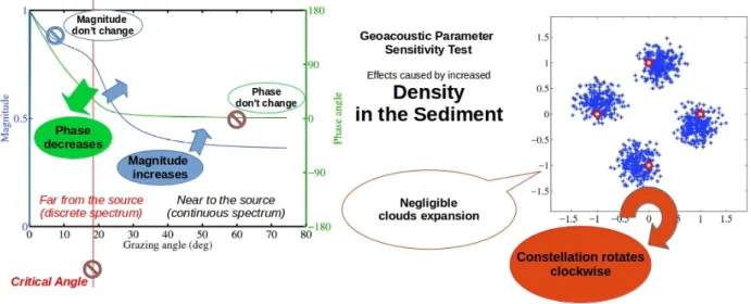
3.3.2 Sensitivity to the density . . . 63
3.3.3 Sensitivity to the compressional attenuation . . . 65
3.3.4 Summary of individual parameter variability effects . . . 67
3.3.5 Joint geoacoustic parameters mismatch test . . . 69
3.4 PTR sensitivity to geometric parameters . . . 75
3.4.1 Sensitivity to the source horizontal velocity . . . 78
3.5 Discussion . . . 82
4 Experimental results 83 4.1 The “Underwater Acoustic Network’11” sea trial . . . 83
4.1.1 General aspects . . . 84
4.1.2 Environmental data . . . 84
4.1.3 Equipment . . . 87
4.1.4 Acoustic data . . . 88
4.2 Experimental results I: comparison of PC-PTR with PC-EPTR . . . 91
4.2.1 Environmental focalization setup . . . 92
4.2.2 “A posteriori” physical parameters . . . 94
4.2.3 Analysis of time-variant CIR data . . . 98
4.2.4 Communication performance analysis . . . 102
4.2.5 Discussion . . . 105
4.3 Experimental results II: introducing the Reg-L1 in the comparison tests . . . 106
4.3.1 Results on communications performance . . . 109
4.3.2 Discussion . . . 111
4.4 Experimental results III: long term analysis . . . 113
4.4.1 Performance analysis . . . 113
4.4.2 Channel identification issues . . . 117
4.4.3 Discussion . . . 119 5 Conclusions 123 5.1 Concluding remarks . . . 123 5.2 Contributions . . . 129 5.3 Future work . . . 130 APPENDICES 132
A Derivation of the minimum variance unbiased estimator 132
B Derivation of the regularized `1-norm estimator 135
C Outliers sensors blocker 138
D Bi-static scattering geometry 141
List of Acronyms
BER Bit Error Rate
BPSK Binary Phase Shift Keying CS Compressed Sensing
CIR Channel Impulse Response
CTD Conductivity, Temperature and Depth DS Doppler Spectrum
DSF Doppler Spreading Function DFE Decision Feedback Equalizer EF Environmental Focalization
EPTR Environmental-based Passive Time Reversal FNO2 Fixed Node 2
FSK Frequency Shift Keying
FsPTR Frequency Shift Passive Time Reversal
BF-FsPTR Beam-forming Frequency Shift Passive Time Reversal ISI Inter-Symbol Interference
IRLS Iterative Reweighed Least Squares
LASSO Least Absolute Shrinkage and Selection Operator LARS Least Angle Regression
LE Linear Equalizer LTI Linear Time-Invariant LMS Least Mean Square
MIMO Multiple-Input-Multiple-Output
MLSE Maximum Likelihood Sequence Estimator xi
xii
MP Matching Pursuit
MFP Matched Field Processing MSE Mean Square Error
MVU Minimum Variance Unbiased estimator OFDM Orthogonal Frequency Division Multiplexer PC Pulse Compression
PLL Phase Locked Loop PTR Passive Time Reversal
16-QAM 16-Quadrature Amplitude Modulation QPSK Quadrature Phase Shift Keying
RLS Recursive Least Squares
RegL1 Regularized `1-norm estimator RIP Restricted Isometry Property SIMO Single-Input-Multiple-Output SNR Signal to Noise Ratio
STU Sub-surface Telemetry Unity SSP Sound Speed Profile
TL Transmission Loss TRM Time Reversal Mirror
TVAPM Time Variable Acoustic Propagation Model UAN11 Underwater Acoustic Network 2011
UANp Underwater Acoustic Network project
uni-SIMO unidirectional Single-Input-Multiple-Output VLA Vertical Line Array
VLF Very Low Frequency 2D two-dimensional
List of Figures
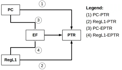
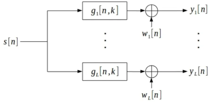
2.1 Methodology to test EPTR and compare performance with PTR: four possi-bilities for channel identification applied to time reversal underwater commu-nications: (i) PTR with pulse compression (PC-PTR), (ii) PTR with `1-norm regularization (RegL1-PTR), (iii) EPTR with pulse compression (PC-EPTR) and (iv) EPTR with `1-norm regularization (RegL1-EPTR). . . 22 2.2 Ocean data model as a Single-Input-Multiple-Output (SIMO) system with L
channels in baseband equivalent representation. Input signal s[n], discrete CIR gl[n, k], noise wl[n] and the output signals yl[n] for the l-th channel. . . 23
2.3 The Passive Time Reversal (PTR) receiver diagram for a SIMO system with L channels in baseband equivalent representation. The received signals yl[n] are
passed through square root raised cosine filters p[n] then through conjugate time-reverse filters ˆgl†[−n] based on discrete CIR estimates ˆgl[n] and then
summed to yield the final PTR output signal z[n]. . . 27 2.4 Snapshot of the hyper-surfaces for `0.5, `1, `2 and `10-norm. . . 31
2.5 Block diagram of the environmental focalizer for EPTR implementation, which is used for obtaining the CIR replica from an “a priori” search space that best matches a CIR snapshot estimate. A set of “a priori” parameters are used to generate the search space of model-based CIR replicas which are optimized, in the sense of best match a CIR estimate, using exhaustive search with a Bartlett processor. The output are the “a posteriori” parameters and the corresponding noise-free CIR replica generated from these parameters. . 34 2.6 Block diagram of a single-input-multiple-output coherent communication
re-ceiver allowing for the implementation of either the standard pulse compressed Passive Time-Reversal or the Environmental-based Passive Time Reversal processors (see text for detailed explanation of the role of each block). . . . 37 3.1 Simplified overview of the acoustic propagation regimes in shallow water
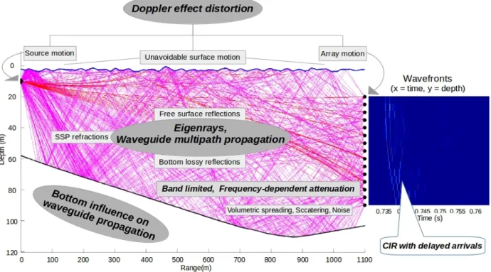
form-ing a waveguide channel after the critical angle and the acoustic propagation physical parameters that affect the waveguide propagation. The envelope of an hypothetic channel impulse response is shown at right. . . 40 3.2 Main issues that affect the propagation in underwater acoustic waveguide
channels. The scenario and its multipath structure (paths in magenta) are shown on the left. The wavefronts are shown on the right (color-plot in blue), showing the hydrophones depth in the vertical axis and time-delayed path arrivals in horizontal axis. . . 43
xiv LIST OF FIGURES
3.3 CIR in 2D representation, obtained from real data of the Underwater Acous-tic Network 2011 (UAN11) sea trial in May 24, 2011, showing 20 snapshots of time-invariant Channel Impulse Response (CIR) estimated with the clas-sical method of pulse compression, each one with a 16 milliseconds duration. Multipath propagation effects are observed as the delayed arrivals along the horizontal time axis. . . 46 3.4 Example of DSF computed from the time-variant CIR, generated with 20
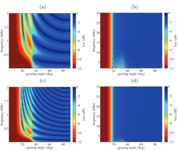
snapshot CIR of 16 ms, of Fig. 3.3. . . 49 3.5 Bottom reflection loss calculated with parameters of Table 3.1 for a
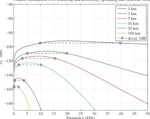
low-frequency regime (a and c) and a high-low-frequency regime (b and d). Sediment layer with 2 m thickness (a and b) and 5 m thickness (c and d). . . 52 3.6 TL (dB) for unbounded media propagation as function of frequency and
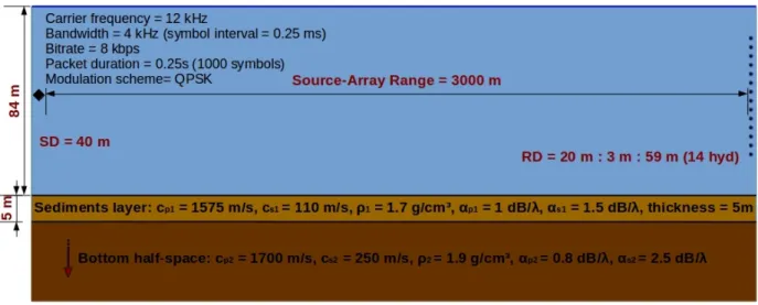
parametrized by source-receiver range. . . 55 3.7 Simulation scenario with the channel physical parameters and the system
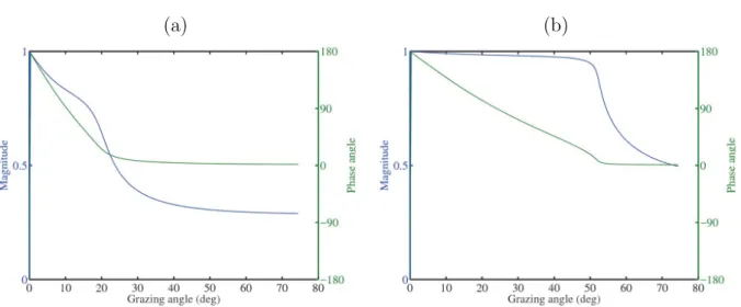
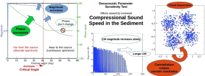
setup parameters. . . 56 3.8 Sound speed profile relative to the scenario for parameter sensitivity testing. 57 3.9 Sediment sound speed effects. The reflection coefficient for a low value (a)
and a high value (b) of sound speed in the sediment layer. . . 60 3.10 Simulated channel impulse responses for a low value 1690 m/s (a), a mean
value 1990 m/s (b) and a high value 2770 m/s (c) of sediment sound speed. . 60 3.11 Variation of compressional sound speed in sediment layer (5m) over bottom
half space (case of cp1 = 1990 m/s shown). . . 61
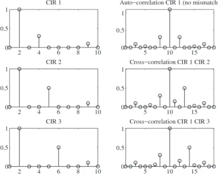
3.12 On the left column are shown an hypothetic CIR, named “CIR 1” and its tap delayed versions “CIR 2” and “CIR3”. On the right column are the auto-correlation of “CIR 1” and its cross-auto-correlation with the tap delayed “CIR 2” and “CIR 3”. The CIR mismatch caused by delayed taps generates a cross-correlation with delayed side lobes, suggesting that some delayed residual side lobe may eventually occurs in the Q-function of PTR. Delayed side lobe in the Q-function would cause phase rotation in the PTR output. . . 62 3.13 Reflection coefficient versus grazing angle for the minimum 1.70 g/cm3 (a)
and maximum 2.65 g/cm3 (b) values in the range for the sediment density
parameter. . . 64 3.14 Density in sediment layer (5m) over bottom half space testing. . . 64 3.15 Reflection coefficients versus grazing angle for the minimum 0.10 dB/λ (a) and
maximum 1.05 dB/λ (b) values in the range for the compressional attenuation parameter. . . 66 3.16 Compressional attenuation in sediment layer (5m) over bottom half space
testing. . . 66 3.17 Reflection coefficient for bottom types: clay, silt, sand, gravel, moraine, chalk,
limestone and basalt, with properties set according to Table 3.2. . . 70 3.18 CIR generated assuming reflection coefficients of Fig. 3.17 for the scenario
described in Sec. 3.2 and for bottom types: clay, silt, sand, gravel, moraine, chalk, limestone and basalt, with properties set according to Table 3.2. . . . 71
LIST OF FIGURES xv
3.19 Receiver constellations computed in a noiseless channel assuming the mis-match between the reference “actual” CIR from sand bottom and each CIR “estimate” of Fig. 3.18 from the reflection coefficients of Fig. 3.17 for bot-tom types: clay, silt, sand, gravel, moraine, chalk, limestone and basalt, with properties set according to Table 3.2. . . 72 3.20 Example of the path structure changing in a simplified waveguide. Bellhop
model eigenrays simulation (launching rays limited to 10 degrees) for source-receiver range of 190 m (a) and 193 m (b). Range-independent transect with 70 m water depth, 1500 m/s isovelocity sound speed profile, 20 m source depth and 50m receiver depth. . . 77 3.21 Normalized CIR modeled for source-receiver range of 190 m (a) and 193 m
(b), with the parameters used in the multipath scenario shown in Fig. 3.20. . 78 3.22 DSF (a,c,e,g and i) and PTR output constellation diagram (b,d,f,h and j) for
a moving source with velocities 0.0 m/s (a,b), 0.3 m/s (c,d), 0.6 m/s (e,f), 0.9 m/s (g,h) and 1.2 m/s (g,h) in the waveguide scenario described in Sec. 3.2. 80 3.23 Trends observed in the results for source horizontal velocity sensitivity testing. 81 4.1 UAN’11 network node position superimposed on the bathymetry map of the
area: FNO# denotes fixed nodes, STU is the Sub-surface Telemetry Unit multichannel array and OBJ# denote AUV mounted mobile nodes. The transect between FNO2 and the STU is 890 m long, and is range-dependent attaining a maximum depth of 100 meters. . . 85 4.2 Sound velocity profiles measured with CTD#4 near the STU location on May
24 (a) and on May 27, 2011 (b). . . 86 4.3 FNO2 - STU transmit-receiver leg during the UAN11 sea trial:
range-dependent transect (890m), source depth 28.2m, 16 hydrophones VLA 4m equally spaced from 14.1m to 74.1m, 5m fluid sediments layer with cp1 1550
m/s, ρ1 1.8 g/cm3 and αp1 0.8 dB/λ, over viscoelastic bottom half-space
with cp2 1550 m/s, cs2 250 m/s, ρ2 2.0 g/cm3, αp2 0.1 dB/λ and αs2 2.5 dB/λ. 86
4.4 Modem Kongsberg cNode-Mini used for single-input-multiple-output acoustic transmissions (left) and a scenario of one transmit-receive leg of the UAN11 sea trial where the modem was used (right). The vertical line array with a yellow subsurface float is the Sub-surface Telemetry Unity (STU) and the source near the shore is the FNO2. . . 88 4.5 Image message used as payload for some of the signals transmitted during the
UAN11 experiment. The Quadrature Phase Shift Keying (QPSK) modulation received signals at 4000 bit/s are processed in this work. . . 89 4.6 Spectrogram of a signal received at hydrophone 1 (deepest, at 74.1 m), with
sound pressure level (SPL) in decibel referred to 1µP a at 1m. Carrier fre-quency 25.6 kHz. The constant stream of 1’s is filling the data packet between seconds 20 and 25. . . 90
xvi LIST OF FIGURES
4.7 Scenario for the transmitter-receivers transect (FNO2-STU): range-dependent 890 m long transect, source depth 28.1 m, 16 hydrophones vertical array 4 m equally spaced from 14.1 m to 74.1 m depth, maximum water depth 100 m, 5 m sediment layer (in dark-yellow color) over bottom half-space (in orange color). The eigenrays are color coded as follows: direct paths in magenta, reflected paths in blue, bottom-reflected paths in red, and surface-bottom-reflected paths in gray. . . 94 4.8 Maximum a posteriori geometric parameters source-receiver range, source
depth and array depth (using the shallowest hydrophone as reference) ob-tained through environmental focalization for each slot of the data set #241 received on May 24 (a) and #275 received on May 27 (b). The three best fit-ness set of parameters are shown: maximum “a posteriori” set (blue circles), second maximum set (red cross) and third maximum set (green cross). . . . 96 4.9 Maximum a posteriori geoacoustic parameters sediment compressional sound
speed, sediment density and sediment compressional attenuation obtained through environmental focalization for each slot of the data set #241 received on May 24 (a) and #275 received on May 27 (b). The three best fitness set of parameters are shown: maximum “a posteriori” set (blue circles), second maximum set (red cross) and third maximum set (green cross). . . 97 4.10 Wavefronts estimated by PC (a) and by EF based on PC (b) for data set
#241 The colorbar shows magnitude in decibel referred to full scale (dBFS). 99 4.11 CIR for the data collected on May 24 for the data set #241 at hydrophone
6 (54.1 m depth) estimated by pulse compression (a) and (b) and modeled through environmental focalization (c) and (d). Time-delay CIR representa-tion (a) and (c) and average magnitude CIR (b) and (d). The colorbar shows normalized magnitude in dBFS. . . 100 4.12 CIR for the data set #275 collected on May 27 at hydrophone 6 (54.1 m
depth) estimated by pulse compression (a) and (b) and modeled through en-vironmental focalization (c) and (d). Time-delay CIR representation (a) and (c) and average magnitude CIR (b) and (d). The colorbar shows normalized magnitude in dBFS. . . 101 4.13 A CIR snapshot comparison: envelope of complex baseband equivalent CIR
obtained by PC estimation (magenta) and by environmental focalization (blue), for hydrophone 6 of the data set #275, slot number 4. . . 101 4.14 Constellation of the data set #241 received on May 24, after being processed
with PC-PTR (a) and PC-EPTR (b), and for the data set #275 received on May 27, after being processed with PC-PTR (c) and PC-EPTR (d). . . 103 4.15 BER results per slot: May 24 data set #241 (upper subplot), PC-PTR
(ma-genta) and PC-EPTR (red); May 27 data set #275 (lower subplot), PC-PTR (cyan) and PC-EPTR (green). The diamond marker denotes an error-free slot. 104 4.16 Mean square error of the received equalized communications signal for the
full array. Results along the 20 slots in the data set #241 on May 24 with PC-PTR (magenta) and PC-EPTR (red), and in the data set #275 on May 27 with PC-PTR (blue) and PC-EPTR(green). . . 104
LIST OF FIGURES xvii
4.17 Channel number 8 estimated CIR from data set #274 with PC (a,b), modeled with environmental focalization by EPTR based on PC (c,d), with RegL1 (e,f) and modeled with environmental focalization by EPTR based on RegL1 (g,h). CIRs time variability (left) and mean power CIRs (right). . . 108 4.18 MSE results of May 27 data (signal identification number 274) with PC
es-timation (blue), RegL1 eses-timation (red), PC environmental focalization (ma-genta) and RegL1 environmental focalization (green). . . 109 4.19 Received symbols along time after processing with the PTR (a),
PC-EPTR (b), RegL1-PTR (c) and RegL1-PC-EPTR (d). The vertical axis denotes the bit pairs corresponding to the angles of recovered QPSK symbols. The horizontal axis is the effective time of payload transmission. . . 111 4.20 Transmitted low resolution image (a), and the recovered image: with
PC-PTR estimation (b), with RegL1-PC-PTR estimation (c), and after processing by EPTR focalization (d ). The corresponding symbol error rates (SER) are given bellow the received images. . . 112 4.21 Mean Square Error (MSE) of soft-decision recovered symbols obtained by
EPTR (green diamonds), Regularized `1-norm estimator (RegL1)-PTR (blue crosses) and Pulse Compression (PC)-PTR (red triangles) along ten data frames between May 24 and May 27. . . 114 4.22 MSE of soft-decision recovered symbols for the data sets #241 and #271 to
#275 after being processed by EPTR (green diamonds), RegL1-PTR (blue triangles) and PC-PTR (red circles). . . 116 4.23 MSE of soft-decision recovered symbols for the data sets #276 to #279 after
being processed by EPTR (green diamonds), RegL1-PTR (blue triangles) and PC-PTR (red circles). . . 117 4.24 Failure in CIR alignment for the hydrophone 8 data set #278. Plots (a), (b)
and (c) show the CIR in 2D representation for PC, RegL1 and EF, respectively. Plot (d) shows the average magnitude CIR computed with PC (red line), RegL1 (blue line) and EF (green line). The first path of EF channel replica wrongly aligned with the second path of PC channel estimate. . . 118 4.25 Correct CIR alignment, in the sense of an accurate time position of the main
path, for the hydrophone 8 data set #274. Plots (a), (b) and (c) show the CIR in 2D representation for PC, RegL1 and EF, respectively. Plot (d) shows the average magnitude CIR computed with PC (red line), RegL1 (blue line) and EF (green line). . . 119 C.1 DSF (a) and the DS (b) relative to a sensor whose the signal has successful
resampling compensation (hydrophone 7 at 50.1 m depth). Ill-posed DSF (c) and DS (d) relative to a sensor with failed compensation (hydrophone 16 at 14.1 m depth). . . 139 C.2 Outliers rejection for PTR for data collected on May 24 (a) and May 27 (b).
Each circle corresponds to the Doppler spectrum maximum peak estimated at each hydrophone. The marks filled with red color denote the outliers and the marks filled with green color denotes the accepted sensors. The two dashed lines shows the thresholds for rejection. . . 140
xviii LIST OF FIGURES
D.1 Bi-static scattering geometry. The transmitter, the point scatterer and the receiver are moving with constant velocity. . . 141 D.2 A simplified underwater waveguide with isovelocity Sound Speed Profile (SSP)
List of Tables
2.1 Procedure of IRLS for solving the quadratic optimization problem (2.21). . . 33 3.1 Geoacoustic parameters used to compute the bottom loss of Fig. 3.5. . . 51 3.2 Geoacoustic properties of continental shelf and slope environments [45]. . . . 59 3.3 Sediment compressional sound speed for the sensitivity simulated test. . . 59 3.4 Sediment density variation range for the sensitivity simulated test. . . 63 3.5 Compressional attenuation variation range for the sensitivity simulated test. 65 3.6 Test for thin sediment layer over half space bottom parameters. . . 68 4.1 Typical geoacoustic parameters in UAN11 area. . . 87 4.2 Frame structure of the transmitted data (size and generator polynomial of
m-sequences). . . 89 4.3 Transmission start times of each UAN11 data frame processed in this work. . 91 4.4 Environmental physical parameters for propagation modeling and focalization 92 4.5 Performance analysis of PC-PTR and EPTR. . . 102 4.6 MSE with PC-PTR, RegL1-PTR and EPTR for ten signals collected in
UAN11 experiment. . . 115 C.1 Blocked sensors per data set in the 16-hydrofones VLA. . . 140
Chapter 1
Introduction
Preview In order to contextualize the main issues in equalization of doubly spread channels, this chapter presents an overview of underwater acoustic communications using wireless sys-tems, reviews the state of the art and shows the motivation of the work for developing a channel compensation method based on inserting acoustic propagation modelling and envi-ronmental focalization in the equalization process. Section 1.1 introduces the issues involved in shallow water acoustic propagation and the consequent requirement for channel equaliza-tion; Section 1.2 reviews equalization for single carrier systems, briefly outlining adaptive equalizers and time-reversal processors. Section 1.3 presents the work motivation and intro-duces the perspective that leads to the proposed environmental-based time-reversal method; and Section 1.4 presents the thesis outline.
1.1
Underwater communications and equalization
Underwater communications is a research area of increasing interest to the scientific com-munity, justified by its potential applications to transmit information for remote control of valves in off-shore oil platforms, ocean research data assessment, telemetry for pollution mon-itoring at sea, communication between divers, control of autonomous underwater vehicles, military underwater communications and underwater acoustic networks, among others.
Cable underwater communication systems are suitable to be used when the transmitter and receiver are assumed static (moored) or when one node is tethered mobile with low
2 Chapter 1. Introduction
tial coverage as, e.g., in the case of underwater Remotely Operated Vehicles (ROV) which have limited mobility. Alternatively, wireless underwater communications could be advan-tageously used to extend the spatial coverage of these mobile devices (or of any other device that may require communication without using wires). Wireless acoustic systems designed for ranges greater than few kilometers tend to have easy operation issues in comparison to cabled devices, in general, due to the absence of a long cable in the underwater scenario. Further, depending on the application, cable and wireless systems may be complementary.
Wireless underwater communications systems use the water medium to propagate signals, which are affected by the physics of underwater propagation. In general, the use of acoustic waves is the standard choice for underwater communications because the attenuation is much lower then that of electromagnetic waves and optical waves are affected by water turbidity [1]. Nonetheless, in some cases electromagnetic or optical waves can also be advantageously employed.
Radio underwater communications can be done from terrestrial transmitters to sub-merged antennas using Very Low Frequency (VLF) band (3-30 kHz), requiring high power land-based transmitters for the signal to cover large maritime areas (few thousands of kilo-meters) and penetrates in sea water with depth in the order of few tens of meters [2]. The Naval Research Laboratory developed several decades ago a frequency-shift keying system which for the first time permitted automatic operation of the Navy’s VLF transmitters at a rate of 60 words per minute with a reasonable degree of reliability for command-control communications with submarines [3]. Since then, systems were significantly improved in terms of data rate although having limited range: for instance, two systems with rate up to 16 kbit/s at distances of 20 meters and rate 1-10 Mbit/s at distances less than 10 meters
1.1. Underwater communications and equalization 3
were developed by Wireless Fiber Systems [4].
Optical underwater communications can operate with very high-rate (order of megabits) and very short range (less than one hundred meters). A modem projected by WHOI [5, 6] for the transmission of information from an ocean observatory has the potential to transfer rates of up to 10 Mbit/s at distances up to 90 meters in clean water with use of a receiver based on photomultiplier tubes and a laser diode emitter. Other examples include one of the newer versions of the AquaOptical [7] modem that achieves transmission rate of 2.28 Mbit/s in clear water at distances of 50 meters or Blueard systems from Sonardyne [8, 9] based on photo-multipliers.
Acoustic waves can propagate to large distances in underwater unbounded media, de-pending on the frequency of operation, and therefore are the solution of choice for underwater communications in applications where wired connection is disadvantageous [1]. For instance, acoustic modems are appropriate in scenarios with ranges greater than one hundred meters in both shallow and deep water. However, transmission loss caused by volume spreading and frequency selective attenuation are factors determining the attainable range and bandwidth in unbounded underwater media, limiting the data rate of acoustic transmission. Moreover, channel impulse response with multipath (which causes time spreading on the received sig-nal) and channel impulse response time-variability (which causes frequency spreading of the received signal) may occur, imposing severe limitations on the system performance.
In severe multipath scenarios it is common to achieve data rates of a few hundred bit/s for coherent communications, at best. In scenarios with mild conditions the data rate can be higher, as described, e.g., in [10], which reported an experiment where a Multiple-Input-Multiple-Output (MIMO) Orthogonal Frequency Division Multiplexer (OFDM)
sys-4 Chapter 1. Introduction
tem achieved a data rate of 125.7 kbit/s over a bandwidth of 62.5 kHz. Two transmitters with 16-Quadrature Amplitude Modulation (16-QAM) and coding were used to reach the results, suggesting that MIMO-OFDM is an appealing solution for high data rate trans-missions over underwater acoustic channels. This scenario had mild conditions because the channel impulse responses in such experiment were, in general, with few multipath delays, extending in a time window of less than 4 ms. Shallow water communication, i.e., when the source-receiver range is several times greater than the water depth, may present long delay time spreading, e.g., more than 15 milliseconds, depending of the scenario, thus causing severe multipath propagation distortion.
This work focuses on shallow water acoustic communication channels, where the acoustic waves propagate with multiple interactions with the boundaries, i.e., the seabed and the sea surface, thus forming a natural waveguide. The acoustic field in such environment is char-acterized by multiple constructive/destructive interferences, yielding a complicated propa-gation pattern that can be predicted by a physical model as, e.g., ray/beam trace model, normal modes model, parabolic equation model, to cite a few. Since the multipath propaga-tion may form channel impulse responses characterized by several delayed arrivals after the first arrival, severe Inter-Symbol Interference (ISI) may occurs, extending to a significant number of adjacent symbols. Therefore, aiming to reduce the ISI and to reach successful message recovery, it is necessary to compensate for the Channel Impulse Response (CIR) distortion in the underwater waveguide by applying a robust coherent channel equalization method, which should be adaptive when in presence of time-variability.
Techniques for underwater channel equalization to mitigate ISI and improve commu-nications performance can be found in several reports in the literature. However, most of
1.1. Underwater communications and equalization 5
them are based mainly on adaptive equalizers, such as, e.g., the Decision Feedback Equalizer (DFE) [1, 11] and/or on time-reversal processors, such as, e.g., the Passive Time-Reversal (PTR) [12, 13, 14], which frequency domain version is known as Phase Conjugation. The DFE principle is to track the inverse channel during a training mode operation to design a adaptive filter which compensates for channel distortions during transmission mode. The PTR principle is to employ the reciprocity property of the wave equation through the use of an array of sensors connected to a multichannel receiver that perform conjugate time-reversal filtering and summing over channels, aiming to compensate for multipath distortion. It re-quires channel estimates for feeding the reverse filters during the message reception period, assuming that the channel is stable in such time interval. More on these techniques are discussed in Sec. 1.2.
Channel identification is a requirement for PTR receivers, where the CIR estimates feed the time-reversal filters. Usually, conventional PTR employs a probe pulse with suitable correlation properties to estimate the channel using pulse compression. However, in real data, the channel estimation with pulse compression method is prone to noise in the received probe signal, decreasing the accuracy of the CIR estimates. The inaccuracy in CIR estimation is an important issue in PTR receivers, that can severely decrease its performance. A different method of channel estimation, that may increase CIR accuracy, is the `1-norm regularization. Since the impulse responses in shallow water channels are characterized by arrival paths and considering that a CIR time window extends sufficiently so that there are few paths with large energy and the other arrivals with very low energy, mostly attributed to noise, then the CIR can be assumed sparse. This assumption opens the opportunity to use the Regularized `1-norm (RegL1) channel estimator, that explore sparse features for increasing the CIR
6 Chapter 1. Introduction
accuracy. It is widely employed in compressive sensing theory [15, 16] and can yield cleaner CIR estimates then pulse compression, due to its higher immunity to noise and path side lobes effects.
This work proposes another different method for CIR identification based on a processor that employs an underwater acoustic propagation model and an environmental focalization algorithm, which is driven by physical information of the environment, to generate the CIR replicas that feed the PTR filters. Whether or not this model-based CIR estimate would be suitable for employment in a real channel compensation problem would depend on the degree of accuracy of the model. Acoustic propagation models require as input a set of physical parameters that represent the environment where the acoustic field is to be predicted. Usually, the parameters are the source/receiver positions and bathymetry (also known as geometric parameters), the density, compressional/shear speed and attenuation of the seabed (also known as geoacoustic parameters) and the sound speed profile of the water column. In a strict sense, such physical parameters are unknown in a real environment. In a wide sense, one may roughly estimate those parameters by assuming that a particular area can be represented by the parameters assessed with some samples collected in-situ with dedicated equipment as, e.g., Conductivity, Temperature and Depth (CTD), thermistor chain, bottom grab, echo sounding and pressure gauge. Also, it may be used knowledge from previous measurements, but this must be carefully addressed to avoid over-outdated environmental data being used so as to no longer adequately represent the scenario.
In real data processing, unfortunately the simple employment of a set of physical parame-ters chosen empirically as input for an acoustic propagation model will hardly represents the actual acoustic field or actual CIR, due to lack of accuracy. It would be necessary to know
1.2. State of the Art 7
the exact parameters that represent the actual environment, which is a hard requirement. However, such requirement can be relaxed through the use of an “a priori” search space of physical parameters which, after optimization, generates the CIR that best matches a noisy observed CIR, in a process named Environmental Focalization (EF). The advantage is to generate a noise-free “a posteriori” CIR replica which, assuming a sufficient accuracy, can substitute the corresponding noisy CIR estimate used as reference during the optimization. As will be shown along this work, to employ the EF method may be a suitable approach to improve the performance of time-reversal communications in shallow water. In this sense, the Environmental-based Passive Time-Reversal (EPTR) is proposed to improve a conven-tional PTR receiver through the insertion of physical information of the environment in the equalization process, using the EF method for CIR identification. The EPTR will be tested with real data and compared with other PTR based receivers using CIR estimation based on Pulse Compression (PC) and sparse CIR estimation based on Regularized `1-norm (RegL1). More on the EF method is discussed in Sec. 1.3 and the EPTR receiver is later described in details in Chap. 2.
1.2
State of the Art
Channel equalization for single carrier systems is reviewed, briefly outlining adaptive equal-izers and time-reversal processors, using as starting point for discussion a short historical review in digital acoustic underwater communications. Further, a discussion on environ-mental focalization and equivalent modelling is done in the context of motivating the need for developing a method that combine acoustic propagation physical modelling and channel equalization.
8 Chapter 1. Introduction
1.2.1
Short historical underwater communication review
Prior to the 1970’s there were a few published reports of acoustic modems. Analog systems were developed as, e.g., an underwater telephone which permitted voice communications between ships and submarines1, but they had no capability for mitigating the distortion introduced by the highly reverberant underwater channel.
During the 1980’s, incoherent systems using Frequency Shift Keying (FSK) modulation were widely employed as the best option in terms of data rate2. Since this modulation scheme is incoherent, it does not require capturing the signal phase to recover the message. At that time, the inability to explore the phase brought the research focus to frequency modulation. Although it has high power efficiency, the bandwidth inefficiency inherent to such systems restricts their use to low data rate transmissions, say less then 1 kbit/sec. The inefficiency is caused by the requirement of sufficiently separate the FSK frequency tones with more than the coherence bandwidth (the inverse of the multipath spread), aiming to avoid frequency aliasing [1]. The search for improving bandwidth efficiency induced to the research on coherent modulation [18].
Several works about coherent underwater communications systems have been published since the 1990’s, e.g.,[12, 18, 19, 20, 21], given that coherent systems are able to overcome the ISI caused by multipath propagation through the employment of equalization algorithms. This more efficient bandwidth scheme contributed to move acoustic telemetry from the well-behaved vertical deep channel (which is a reduced multipath channel) into the more
1The underwater telephone, designated the AN/UQC, was developed by the US Navy, being a suppressed
carrier single side band amplitude modulation (SSB) system operating on a carrier frequency of approxi-mately 8 kHz, as described in [17].
2In fact, note that FSK is still widely used nowadays in applications at which low data rate, e.g. less
1.2. State of the Art 9
ill-posed horizontal shallow water channel (which is a severe multipath channel). Most of the coherent modems used a Linear Equalizer (LE) or a Decision Feedback Equalizer (DFE), coupled with Phase Locked Loop (PLL) for carrier synchronization [11, 21]. Also during the 1990’s, research on time-reversal were developed [12]. In 1996, Kuperman et al., based on an experiment conducted in the Mediterranean Sea, performed an experimental demonstration of an acoustic time-reversal mirror [19]. After, avoiding the high complexity of DFE, the passive time reversal receiver [14] emerged as a low complexity channel compensation method to reduce ISI due to multipath, based on conjugate time-reverse filtering applied to the signals received in a vertical array of hydrophones spanning the water column.
During the 2000’s, time-reversal phase coherent underwater communications was pro-posed [22] and since then used in several works as , e.g., in [23, 24, 25, 26, 14].
Nowadays, channel compensation for coherent communications in shallow water often relies in the combination of adaptive DFE equalization and PTR methods.
1.2.2
Adaptive equalizers
The adaptive DFE is a standard coherent underwater acoustic communications processor, early employed in single-input-single-output transmissions [21]. It originates from earlier stage non-adaptive equalization that aimed to eliminate ISI by designing an inverse filter to revert the distortion caused by the channel, under the assumption that the channel behaved as a FIR filter with additive noise3. As described in [11], this former non-adaptive processor is
the so-called Zero-Forcing Equalizer. The implementation of error minimization of the filter coefficients using the MSE criterion leads to the LE [11]. Depending on the tap spacing,
3In fact, the linear equalizer is a FIR filter while the DFE is a IIR filter due to contain a feedback part
10 Chapter 1. Introduction
which could be the inverse of the symbol interval or a fraction of it, the LE is still called, respectively, symbol spaced equalizer or fractionally spaced equalizer.
The LE is a suboptimal detector that minimizes the MSE using a transversal filter. The optimal detector is the Maximum Likelihood Sequence Estimator (MLSE), in the sense that it minimizes the probability of a sequence error. The MLSE can be implemented with the Viterbi algorithm [27]. The DFE is a sub-optimum detector composed by a forward filter and a feedback filter that aims at a better performance than the LE, which uses only a forward filter. The feedback filter aims at removing the part of the ISI of the present estimated symbol caused by previously detected symbols.
In non-adaptive DFE (and LE) the CIR is assumed known in the receiver [11]. However, since in many communications systems the channel characteristics are unknown and the channel is often time-variant in some degree, then the adaptive DFE or adaptive LE were proposed.
Adaptive equalizers may employ the Least Mean Square (LMS) algorithm or the Recursive Least Squares (RLS) algorithm to iteratively perform error minimization, requiring a probe training sequence to adjust the filter coefficients during training mode. After reaching convergence, the processor performs equalization during a direct-decision mode. Also, equalizers that do not use the probe training sequence are proposed in [11], performing the so-called blind equalization.
The standard adaptive DFE is accurate and broadly used in aerial wireless communi-cations. However, in wireless underwater communications a lack in robustness may occur mainly due to error propagation issues, a problem inherent to the iterative algorithm
con-1.2. State of the Art 11
vergence, specially in long frames [28]. Additionally, the DFE can be used in multichannel instead of the standard single channel configuration, aiming to yield more robust equaliza-tion, as proposed in [29, 30].
1.2.3
Time-reversal processors
Time-reversal processors use for a vertical array of transducers the reciprocity principle of the linear wave equation. Assuming an acoustic signal being transmitted from a source to the array of transducers, if the received signals are time-reversed and retransmitted, the energy of the retransmitted signals concentrates with constructive interference on the position of the source. This principle drives the active Time Reversal Mirror (TRM) in underwater communications [19, 24]. As described by Kuperman [31], the TRM produces a real acoustic image of the probe source (PS) by converting a divergent wave emitted from the acoustic PS into a convergent wave focusing on the PS. A TRM can be realized by an array of transducers. The incident signal is received, time reversed, and retransmitted from an array of sources collocated with the receivers.
The PTR processor, instead of transmitting the time-reversed signal through the ocean channel from the receiver to the source, performs this operation in a computer to filter the incoming transmitted signal. A description of PTR can be found in [14] and in a large body of work in the literature. Despite its simplicity, PTR requires a sufficiently long and dense array to reduce ISI, avoiding poor sampling of the high-order modes [19, 23, 32]. Also, it requires time stationarity which is inherent to the whole PTR process. CIR estimates are required, being typically obtained by correlating each received distorted probe signal with the transmitted probe signal, resulting in a noisy estimate of the channel Green’s function.
12 Chapter 1. Introduction
Such standard CIR estimation technique is equivalent to the pulse compression, commonly used by radar and sonar to increase the range resolution and the signal to noise ratio. The channel must be nearly time-invariant since PTR can not capture time variability until the next probe.
Further, the PTR has much lower complexity than the adaptive DFE, because the former is mostly based on cross-correlation operation. Also, PTR is more robust than the adaptive DFE because the latter can have algorithm convergence issues when using long frames [28]. However, PTR is less accurate than DFE in the sense that significant residual ISI remains in the PTR output signal, as described by Stojanovic in [33].
A processor derived from PTR is the Frequency Shift Passive Time Reversal (FsPTR), proposed in [32]. Although PTR allows for the implementation of a simple communications system, it loses performance in the presence of geometric mismatch between the probe signal and the actual data symbols transmission. Assuming that geometric mismatch, in depth and range, could be partially compensated by applying an appropriate frequency shift in the PTR operator, real data results are presented in [32] with Binary Phase Shift Keying (BPSK) modulation scheme and carrier frequency 3.6 kHz. A gain is expected for FsPTR over PTR due to the fact that the processor in some degree compensates for the channel variability. The results showed FsPTR achieving an overall gain of approximately 4.11 dB over a conventional PTR processor.
Another PTR-based processor is the Beam-forming Frequency Shift Passive Time Re-versal (BF-FsPTR), proposed in [34]. Considering the fact that each multipath wavefront may be assumed independent, the BF-FsPTR apply an independent frequency-shift to each wavefront, aiming to compensate for the channel variability. The wavefront means a surface
1.2. State of the Art 13
containing points affected in the same way by a propagating wave at a given time. It is expected that the BF-FsPTR yields gain over a FsPTR processor because the latter uses just a single frequency shift to all wavefronts, resulting in performance degradation. Real data results are presented in [34], using a frame with bit rate 2 kbit/s and BPSK modulation scheme, showing that the BF-FsPTR, using angular range of the beam-former from -10 to +10 degrees, yielded a mean gain of 2.2 dB over the FsPTR, in terms of mean square error. A probe-based channel estimation method is required by PTR (and by the methods based on it). In its conventional form, the CIR estimates are obtained using Pulse Compression (PC), which is a signal processing technique performed by transmitting a probe pulse and then correlating the received signal with the transmitted pulse. A theoretical derivation of PC can be done from the Minimum Variance Unbiased estimator (MVU) [35], as described in Appendix A. In case the channel is approximately sparse, where the CIR, in a discrete version, is a nearly sparse vector4, the classical PC channel estimation (based on `2-norm)
can be substituted by an approach that includes the Regularized `1-norm (RegL1) in the `2-norm estimation problem. The advantage is to generate sparse CIR estimates less prone to noise effects, making the channel identification process more accurate. Since PTR is very sensitive to errors or inaccuracies in CIR estimates, the RegL1 is an attractive approach to improve the PTR performance.
Furthermore, using an environmental model-based approach for CIR identification, this work proposes to modify a conventional PTR receiver, replacing noisy CIR estimates by noise-free CIR replicas generated by a physical model and optimized by an environmental focalization algorithm. Such method is next discussed in Sec. 1.2.4.
4The vector is assumed sparse whether few elements of the vector have high values and the others have
14 Chapter 1. Introduction
1.2.4
Environmental focalization and equivalent model
In the context of incorporate acoustic propagation physical parameters in the process of equalization of shallow water communication channels, the EPTR uses the Environmental Focalization (EF). The form to include physical parameters in underwater acoustics is via numerical propagation models. Although numerical models have not been used in underwater acoustic communications, they have been proven successful in techniques such as matched-field processing (MFP) for source localization, initially proposed by [36] and [37], (see details in [38] and an overview in [39] and references therein); ocean acoustic tomography (OAT) [40, 41]; and matched-field inversion (MFI) for generic environmental parameter estimation [42, 43]. There exists a large body of work, with a variety of processing techniques with their particularities and application fields, but they all have one common feature: they feed environmental information in numerical models and compare the output to experimental data.
The EF is based on the process of tweaking the “a priori” environmental parameters contained in a search space that, after being optimized under the criterion of a particular objective function, generates the “a posteriori” physical parameter that corresponds to the acoustic field replica that best matches the observed acoustic field. In this work, we are interested in obtain the “a posteriori” CIR instead of an acoustic field. By expanding the number of parameters in the search space to include an additional narrow search over parameters previously known “a priori”, the EF may reach a better adjustment in the objective function, thus making it possible to reduce mismatch between the CIR replicas and the CIR estimate.
1.2. State of the Art 15
Collins et. al. [43] first demonstrated the EF in source localization, showing that the acoustic adjustment was increased if, not only the unknown parameters were included in the parameter space, but also the known parameters, which resulted in that the known ones would vary to slightly different values, improving the acoustic adjustment and thus improving the location of the source. Eventually the search space was adjusted differently to the known and unknown parameters, being more restricted to the first ones and more extended to the second ones.
The EF yields an equivalent model driven by the better combination of parameters that maximizes the acoustic field adjustment. The concept of using a equivalent model is fully described in [44] and essentially consists in employing a set of acoustic propagation physical parameters to generate an environmental model that maximizes a particular objective func-tion, regardless on whether that parameter set in fact represents the actual environment. The environmental model is named “equivalent” in the sense that it better matches with the observed channel under the metrics of the objective function.
The acoustic field is defined by a large set of environmental properties, which vary with space and time. Due to the limitations in observing these quantities with a fine space-time discretization, it is essential to know the degree of dependence of the acoustic field on each of them. Therefore, when aiming to use techniques as matched field processing or environmental focalization, for which the equivalent environmental models are a by product, one of the first steps is to understand the relative importance of each environmental parameter. In this sense, an analysis based on a set of simulations is later performed in Chap. 3 on the sensitivity of physical parameters of the environment.
16 Chapter 1. Introduction
since there is a correlation between the effects of some physical parameters on acoustic propagation. For example, a high density on the seabed is expected to occur along with a high compressional sound speed on the seabed, because both are found on a high reflection seabed (see typical geoacoustic parameters in Table 3.2 [45]). Thus, in this sense, the seabed density and the seabed compressional sound speed are correlated. In [44], Martins presents a study quantifying the compensation between several parameter pair for a transect with 5 km source-receiver range and frequencies multi-tones in the 100-1000 Hz band. Such work clearly shows, for low frequency band, that a significant compensation between different acoustic propagation physical parameters may occurs.
Therefore, in order to obtain an accurate CIR replica in a situation of environmental mismatch, the EF must find a set of environmental parameters that, in some degree, com-pensate for that mismatch. These parameters form the equivalent model obtained from the best combination between the CIR replicas in a given search space and the CIR estimate. Even if this equivalent model does not actually correspond the real environment, the CIR it generates is the closest to the CIR estimate used as a reference for optimization, with the advantage of being noise-free. This noise-free CIR replica can replace a noisy CIR es-timate in PTR, and if the former is sufficiently accurate, communications performance can be increased.
1.3
Motivation
The motivation of this work is based on (i) the need to perform channel equalization in coherent underwater acoustic communications, specially in shallow water, and on (ii) the possibility of including information on the physics of acoustic propagation in the process of
1.3. Motivation 17
channel equalization, because the physical parameters of propagation severely influence the channel impulse response. It is expected that using the environmental focalization method to obtain noise-free modeled CIR estimates for feeding time-reversal filters, we can lead to improved communications performance, assuming that a low level of modeling error is achieved by the EF processor. The method relies on ray trace numerical modelling to compute the impulse response of shallow water waveguides and on an EF algorithm designed to compute the channel impulse response replica that best matches a channel estimate. Also, the method must be validated by successful results of real data processing from a coherent underwater acoustic communication sea trial.
Taking into account that: (i) shallow water communication channels present multipath propagation where the CIR is composed by path delays spread in time, and if not com-pensated or equalized, such channel severely degrades the communication performance; and (ii) inevitably the CIR and its variability in space and time is related to the same variabil-ity of the physical parameters of the channel; we formulate the following set of hypothesis: (i) the use of a physical model driven by a particular set of physical parameters chosen to represent the actual environment can generate a CIR estimate that is accurate enough to perform channel equalization with real communications data; and (ii) the computation of a CIR sufficiently accurate for successful channel equalization can be automatically performed by an optimization algorithm that focalizes, from an “a priori” search space, an accurate “a posteriori” CIR replica to compensate the channel. In this thesis the above hypotheses are extensively tested with the goal of improving communications performance through the inclusion of physical information of the channel, collected from the environment where the system is employed. The Environmental-based Passive Time Reversal (EPTR) processor is
18 Chapter 1. Introduction
proposed in this context, and its expected advantages are two fold: increase communications performance through noise effects mitigation in CIR estimates; and make the communica-tions system more robust because the physics of the channel where the system is located is included in the equalization process.
1.3.1
Promissory perspective
This work proposes to incorporate physical information of the environment where the com-munication signals propagate, through the use of physical numerical models, in the process of equalization of shallow water communication channels based on a PTR receiver. The EF (as well as MFP) feeds environmental information in a numerical model and compare the output to real data. In that sense this technique is called as “model-based” as opposed to “data-driven” only.
Many studies carried out with model-based techniques refer the difficulties to favorable compare modeled and experimental data in the high frequency range, say, above 2 kHz. This seems to be the reason why, to the best of the author’s knowledge, there are no reports on the usage of physical numerical models to design CIR replicas for channel equalization of real underwater acoustic communications data. In our case we are not interested in phys-ical parameter estimation (as would be the case of MFP), but solely in CIR modeling for the EPTR. The physical models Bellhop and Bounce [46, 47] are used as forward acoustic propagation models for generating CIR candidate replicas search space. EPTR has a draw-back of expending more computational cost than PTR. In spite of that, the advantages of EPTR over the conventional PTR are to achieve noiseless CIR estimates and perform chan-nel compensation together with a (secondary) physical parameters assessment. The noiseless