Abstract
This paper is focused on experimental evaluation and comparison of progressive damage behaviors in adhesively bonded single lap and double butt lap joints between aluminum and glass fiber reinforced plastic (GFRP). The effect of joint design and dissimilarity of ad-herents on damage evolution of adhesive bonding under tensile quasi static loading is analyzed. Bonding was created by toughened epoxy adhesive as one of the most important and widely used structural adhesives in aerospace, automobile and marine industries. Due to structural behaviour complexity of adherents and adhesive, the frac-ture takes place under mixed mode and the failure mechanism is characterized by the de-bonding area for the proposed joints. The results show that single lap joint could carry up to 30% more tensile load than the double butt lap joint with the same material proper-ties while a combined failure mechanism could be observed and the most dominant ones were yielding of aluminum substrates, adhesive failure at bond-line on aluminum surface and cohesive failure of up-per mat layers of composite material.
Keywords
Adhesive bonding; progressive damage; fracture; cohesive failure; lap joint.
An experimental investigation of static load capacity of AL-GFRP
adhesively bonded single lap and double butt lap joints
1 INTRODUCTION
Different light weight materials such as glass fiber reinforced plastic (GFRP) and aluminum have been used widely in many applications such as marine and aerospace industries in recent years due to their high strength to weight ratio. Using dissimilar materials inevitably necessitates connections of the composite to the metals. The joining of GFRP/Al, which mainly includes both adhesive bond-ing and traditional mechanical connections, is attractbond-ing more and more attentions. Compared with the traditional mechanical connection, adhesive bonding has the unique advantages of reducing the
Rouhollah H. Goudarzia Mohammad Reza Khedmatib
aPhD Candidate, Department of Marine
Technology, Amirkabir University of Technology, Tehran, Iran
bAssociate Professor, Department of
Ma-rine Technology, Amirkabir University of Technology, Tehran, Iran
Corresponding author: a[email protected]
http://dx.doi.org/10.1590/1679-78251760
weight, increasing the fatigue life of joints, having better environmental resistance and wide adapta-bility to the materials. As an example, adhesive bonding will replace the traditional mechanical double butt connection by a double butt connection between GFRP and Al. There are many applications in the marine field for the adhesives such as for the bonding of the hull to the deck, the channels running through the deck, the sea chests, the exhaust system, engine compartment (Diez de Ulzurrun et al., 2007; Baur et al., 2004; Cao and Grenestedt, 2004).
The mechanical relationships and the failure processes of adhesive joints are typically very com-plex. The joint strength is influenced by many properties such as type of adhesive, type of adherents, the bonding length and thickness (Di Bella et al., 2013; Baldan, 2004; Da Silva and Adams, 2006). Failure initiation will usually occur under mixed mode loading in adhesive joints and non-linear effects have to be included. These effects should be better understood in dissimilar adhesively bonded joints because of the adherent different material properties.
It is appropriate to develop reliable integrity assessment methodologies and testing procedures in order to deal with damage and fracture events occurring during loading of adhesive joints. Analytical tools obtained from closed-form solutions have been well developed (Da Silva et al., 2009), particularly for the structural analysis of some single/double strap lap adhesive joints, providing the solutions for the displacement, strain and stress fields for both the adherents and the adhesive. In cases where complex geometries and non-isotropic materials are present, accompanied with material and geometry non-linearity, numerical solutions are mostly preferred. Under the framework of Finite Element Meth-ods (FEM), fracture mechanics can be utilized to assess the structural integrity of adhesively bonded joints (Li et al., 2006; Khoshravan and Mehrabadi, 2012). Most of these approaches are based on comparisons of a parameter (a function of load and geometry), usually the strain energy release rate Gi or Ji (i = Mode I, II and III), with the fracture toughness (Gci or Jci). The limitation of traditional fracture mechanics techniques is that an initial crack must be predefined in the adhesive layer or at the adhesive-adherent interface and self-similar crack growth is assumed. Recent numerical develop-ments in this area are focused on cohesive zone modelling (CZM) techniques, which utilize damage and fracture mechanics, in a way that prediction of crack initiation and subsequent non-self similar progression of cracks has been made possible (Liljedahl et al., 2006; Li et al., 2005; Gustafson and Waas, 2009). Cohesive elements can be embedded at the adhesive–adherent interface to predict in-terfacial fracture, or in the bulk adhesive to predict cohesive fracture. Cohesive zone models require a constitutive law for the adhesive layer and it is necessary for modelling the de-cohesive behaviour of any adhesive or laminated system, it is also necessary to consider the assumptions that are made in computing these values from experimental results.
In literature many models have been proposed that try to cover all effects playing role in adhesive bonded joints, but up to now the failure load and damage propagation assessment of adhesive joints is still not fully understood and the experimental approach is usually conducted in order to understand the behaviour of bonded joints.
Progressive damage behaviours in adhesively bonded single lap and double butt lap joints between aluminum and glass fiber reinforced plastic (GFRP) are studied experimentally in this article. The effect of joint design and dissimilarity of adherents on damage evolution of adhesive bonding under tensile quasi-static loading is analyzed. Structural toughened paste two component epoxy adhesive is used in order to bond the connections.
2 ADHESIVELY BONDED FAILURES
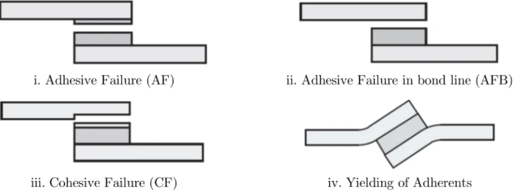
An overloaded adhesive joint can exhibit failure in several different modes. Yielding of adherents due to their low strength or de-lamination which is typical in fiber reinforced plastics or failure in the adhesive bond itself can occur, whereas a cohesive failure in the adhesive is the most common type of adhesive bond failures. It is typically connected with damage initiation and propagation close to the bond-line interfaces. An adhesive failure in the bond line of adhesive and adherent is more likely to occur when the bond-line is weakened in the manufacturing or by environmental degradation. Figure 1 shows different possible types of failures to occur in adhesively bonded joints. In many situations a combination of the given failure modes will occur in a failure process of an adhesive joint. An example for that is a lap joint which initially shows yielding of the adherents, then it leads to cohesive failure of the adhesive due to increased peel stress in the changed geometry (Fig. 1 (iv)) (WeiSgraeber and Becker, 2013).
i. Adhesive Failure (AF) ii. Adhesive Failure in bond line (AFB)
iii. Cohesive Failure (CF) iv. Yielding of Adherents
Figure 1: Failure types of adhesive joints (WeiSgraeber and Becker, 2013).
The response within an adhesive layer is very similar to that in a co-cured interface. The stresses governing a de-bonding process are the normal tensile stress perpendicular to the adhesive plane and the shear stresses parallel to the adhesive plane, which are also responsible for de-lamination. Hence, the de-bonding mechanisms of an adhesive joint can be classified in the well known de-lamination modes: mode I normal opening, mode II sliding shear, and mode III scissoring shear as illustrated in Fig. 2.
Mode I Mode II Mode III
Figure 2: Different modes of fracture.
3 EXPERIMENTAL WORK
3.1 Materials
The specifications of the materials used in the experiments are as follows:
Aluminum parts are cut from plate of cold rolled aluminum alloy 5083-H32 with a thickness of 4 mm. Al Alloy 5083-H32 is known for its exceptional performance in extreme environments and is highly resistant to the attack by both seawater and industrial chemical environments, besides retaining exceptional strength after welding.
GFRP parts are cut from composite sheets of 4 mm thickness. Layers of woven fibers (0/90) of Plane-Eglass type and Epolam 2015 epoxy resin with Epolam 2018 hardener are used to make com-posite sheet by pressing them for 8 hours in a furnace under 80°C. The laminate consists of four layers of 100 g/m2, three layers of 400 g/m2 and four layers of 825 g/m2 woven fibers.
All substrates except the composite laminate were degreased in acetone. After the overlap, area of all the substrates has been treated mechanically with abrasive paper (P180). The residual particles remaining after mechanical abrasion were removed by pressurized air and again cleaned by acetone. Adhesive was the Araldite 2015 A/B from Huntsman Advanced Materials GmbH, Switzerland. Araldite 2015 is a two component toughened epoxy, room temperature curing adhesive giving a resil-ient bond. It is particularly suitable for dissimilar substrates bonding. The weight ratio of the epoxy A with the hardener B was 100:100. Once reticulated, this adhesive has a density of 1.4 g/cm3, a Young's modulus of 2 GPa, a shear modulus of 0.9 GPa, a lap shear strength of 16 MPa and a tensile strength of 30 MPa (according to the manufacturer) at room temperature. The Araldite 2015 com-ponents A and B were mixed and the curing cycle was a 72 hours isotherm at room temperature 25°C and 95% RH.
3.2 Adhesively joint samples
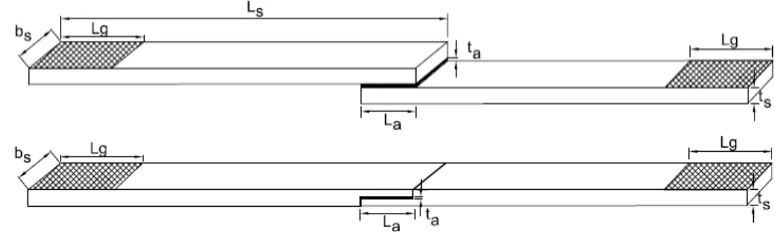
Single lap joint is generally the simplest and cheapest of all joints to manufacture due to its simple design and easy assembly. It was chosen for the test according to the standard ASTM D1002 for determination of joint shear strength. The double butt lap joint has the benefit of keeping the total thickness of the joint at a same value along the substrates and minimizing the bending effects due to straight load line. It has good resistance due to keeping in touch the frontal surface of substrates in the same manner of butt joints and because of that, this kind of joints may also be known as double butt lap joints. Configuration and dimensional properties of these joints are shown in Fig. 3. Length (Ls) and width (bs) of the total substrates were 224 mm and 25 mm, respectively. The bonding
length (La) was 25 mm. The griping length (Lg) on both sides of each base material was 46 mm.
The adhesive thickness was maintained at 0.3 mm. To do this for single lap joints, a dummy of same dimension as base material was aligned in front of one of the first base material and fixing them from lateral movement by some blocks. Then a filler of desired thickness was put along dummy base material. While the bonding areas on both base materials are saturated by adhesives, the second base material was fitted above filler. For double butt lap joint, filler was attached temporary to one of the base material and both of them were aligned on a flat surface while touching face to face. Five specimens of each type was prepared according to this procedures.
Figure 3: Configuration of single lap joint and double butt lap joint.
(a) Single lap joint
(b) Double butt lap joint
Figure 4: Typical AL-GFRP specimens.
The average shear stress is obtained by the formula
P A
(1)
where P is the tensile load and A is the joint overlap area. Since the stress state along the adhesive
bond line is complex, maximum elastic shear stress for lap joints can be evaluated by Volkerson’s formula (Da Silva et al., 2009) as follows;
max 1
coth tanh
2 2 1 2
(2)
where,
1 1
2 2
E t E t
(3)
and,
22
1 1
1 a
a
G l E t t
(4)
where ti and Ei (i 1, 2) are the thickness and elastic modulus of substrates, respectively. Also, ts
be selected so that is calculated less than 1. The above formulas does not include the bending stress due to eccentricity of loading, however, a closed-form solution has been proposed for unbalanced (dissimilar) lap joints with inclusion of adherents’ deformations and bond thickness (Zhao et al., 2011).
3.3 Test procedures
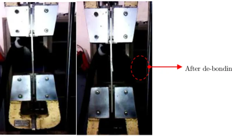
A Zwick-Z1494 Universal Testing Machine, equipped with a 500 kN load cell was used to test the specimens under quasi-static tensile loading with displacement rate of 1 mm/min. The gauge lengths were kept 132 mm along the clamps. A self locking mechanical type clamp was used to fix the speci-men ends to machine, instead of hydraulic clamp (Fig. 5). In order to avoid specispeci-men ends from slipping of clamps, the clamping areas on specimens were mechanically abraded for better sticking. For single lap joints, the bending effect due to out of centre of load line was included and no means were provided to avoid this effect.
Figure 5: A typical test setup.
As the load was increased gradually at the rate of 1 mm/min, the load-displacement curves were plotted online by PC software. The load-displacement results were followed until final drop on the curves due to fracture of bonded joints and its failure to carry out more loads. The data was recorded and saved by the computer. These data were extracted and used for further analyses.
4 RESULTS AND DISCUSSIONS
Figures 6 and 7 show the load-displacement (P ) curves for the test specimens under the
investi-gation. Some levels of noises may be observed in data that may be due to specimens size which is small compared to machine load cell capacity. As it is seen, the load-displacement curves are linear in most of the parts and after reaching the maximum loading, the capacity suddenly drop down. Actually the high visco-elastic nature of the toughened adhesive made it easy to identify the critical fracture load. As a conservative measure, the critical load at failure is the point of maximum tensile loading. The crack initiates as critical fracture load is reached and then grew suddenly so that a drop in loading capacity is observed.
After de-bonding
Figure 6: Load-displacement curves of AL-GRFP single lap joints.
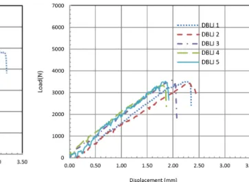
Figure 7: Load-displacement curves of AL-GRFP double butt lap joints.
The results of P curves for double butt lap joints have good similarity and the maximum loading
capacities are approximately identical. In contrast, single lap joints have more scatter in maximum load and displacement at the points of fracture. Table 1 shows the results of the tests at the points of fracture. The minimum fracture load among the single lap group is 3952 N at displacement of 2.36 mm for SLJ2, while a maximum fracture load is obtained for SLJ4 with 6172 N at 2.76 mm displace-ment. For double butt lap joints, the maximum fracture load is 3571 N at 1.98 mm displacement and minimum fracture load is 3342 N at 1.81 mm displacement. As it is seen, the mean value of the fracture load in single lap joints is 5206 N which is 30% greater than the mean value of double butt lap joints which is about 3478 N. This means that for the same base material and adhesive, the single lap joints exhibit more strength than the double butt lap joints. The reason for this is explained in next section.
Test Samples Fracture tolerances Average value Standard deviation
f
P (N) f(mm) Pf(N) f(mm) (MPa) Pf(N) f(mm)
Sin
gle
la
p
jo
in
ts
SLJ1 4876 2.85
5206 2.65 8.3 851 0.20
SLJ2 3952 2.36 SLJ3 5730 2.73 SLJ4 6172 2.76 SLJ5 5303 2.54
D
oubl
e b
ut
t
L
ap j
oi
nt
s DBLJ1 3505 2.25
3478 2.04 6 86 0.23
DBLJ2 3459 2.3 DBLJ3 3571 1.98 DBLJ4 3342 1.81 DBLJ5 3515 1.85
Table1: Fracture tolerances of adhesive bonded joints.
The mean of average shear stresses can be calculated from equation 1 for single lap and double butt lap joints as 8.3 MPa and 6 MPa respectively. This is different from factory specifications of adhesive static shear strength (16 MPa). This can be related to the fact that in lap joints, maximum shear stress occurs at discontinuity of bonding edges which is too much greater than that of average stress. For example from equation 2 and assuming 1, maximum shear stress can be about 2.7 times greater than the average shear stress. The other fact that should be considered is that in fracture analysis of interfacial bi-material systems, both strength and energy properties of adhesives should be considered to understand the initiation and propagation of damages. Techniques such as cohesive zone models are proposed for this matter (Liljedahl et al., 2006; Li et al., 2005; Gustafson and Waas, 2009).
The standard deviation value for fracture load of single lap joints is more than that of double butt lap joints, while an approximately equal deviation value is observed for displacement in both joint types. The main reasons for this may be due to presence of different amount of adhesive failure on surface of composite (As will be seen in table 2) which mainly relates to bonding quality and surface strength of composite. This effect is weakened for double butt lap joints, since the surface of the same composite materials is machined at bonding area to get the desired thickness (half of the thickness is removed), and thus the internal bi-directional fabrics (not mat layer) are attained and prepared for bonding to aluminum.
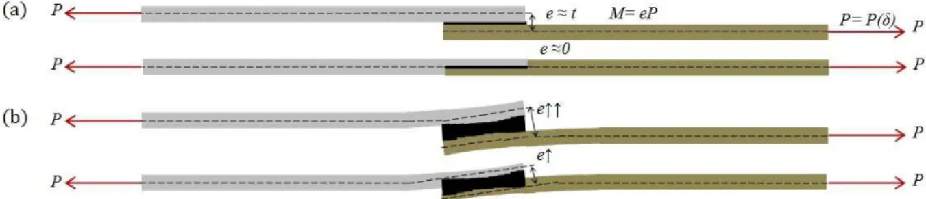
It should be noted that in all test specimens, a relatively large nonlinear rotation was observed in the substrate during loading. The plastic rotation remained in aluminum material after unloading, so that these substrates were not essentially linear elastic at the state of the failure. Although the GFRP substrates rotated largely, there was no deformation remained and they returned to initial state elastically. It should be noted that there would be an eccentricity (e) in loading line for both types
of the joint due to their unsymmetrical configurations in which for the single lap joint this is more than the double butt lap joint. The out of centre of load line causes initial bending moments to be applied on bonding surfaces and by increasing load, the peel off stress increases at the bond line, which causes more bending deflection in adherents until de-bonding of the joints (Fig. 8).
Figure 8: Eccentricity of loading condition on joints: (a) initial state. (b) (exaggerated) during failure.
4.1 Failure mechanism analysis
Fracture in adhesive bonding is contributed to energy release rate (Papini et al., 1994). The main energy release rate is due to axial, torsion and bending strains. Here, the energy release rate is mainly
due to bending strain and a little contributed to the axial strain while the torsion strain can be neglected. The axial strain energy release rate is inversely related to the adherents’ thickness (cross sectional area) for a fixed load. Thus, for the double butt lap joints with lower thickness (cross sectional area) of the adherents at the bond-line, the axial strain energy release rate is more than that for the case of single lap joints.
The energy release rate due to bending, however, will increase or decrease depending on two main factors. The first one is the flexural rigidity, which will increase by adherents’ thickness, resulting in lower bending energy release rate for a fixed load. In addition, the second one is related to the offset of centroid for the loading line. As a result of such an offset, bending moment will increase for a fixed load in case of the single lap joint which is more unsymmetrical compared to double butt lap joint. Thus, in case of single lap joints compared to the case of double butt lap joints, bending strain energy release rate will be more from the viewpoint of bending moment (offset) criterion and will be less from the viewpoint of flexural rigidity at bond-line.
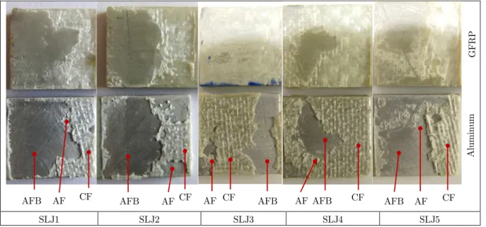
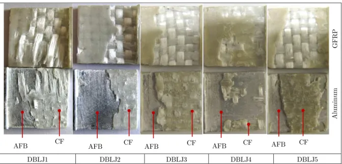
The induced bending moments in both joint types tend to peel off the adherents from the end of the joints. Besides, as a result of the higher flexural rigidity at the bond-line of single lap joints, the overall energy release rate become less than that of double butt lap joints. This causes the single lap joint to tolerate more loads and exhibit higher displacements than the double butt lap joints. The failure mechanism of adhesively bonded joints may be different in nature and it can be cate-gorized in four main mechanisms as already explained. While the bending moment causes the bond-line to be under mixed-mode (I, II) loading, the de-bonding process may not be just in one category and a compound fracture mechanism can occur due to global and local effects. Figures 9 and 10 show the failure mechanisms on surfaces of the samples in high resolution photos.
SLJ1 SLJ2 SLJ3 SLJ4 SLJ5
Figure 9: Fracture schemes on single lap joint surfaces.
As illustrated in the Figs. 9 and 10, the most dominant failure mechanism observed in the joints is the failure at the bond-line (AFB) on the aluminum substrates and cohesive failure (CF) on the
AFB AF CF AFB AF CF AF CF AFB AF AFB CF AFB AF CF
G
F
RP
A
lum
inum
DBLJ1 DBLJ2 DBLJ3 DBLJ4 DBLJ5
Figure 10: Fracture schemes on double butt lap joint surfaces.
composite substrate. Cohesive failure in all samples was due to delaminating of upper layer of the composite substrates at the regions of bonding. This is due to composite low transverse (through the thickness) strength. There was also a little failure observed within adhesive layer (AF) which is a desirable structural performance in an adhesive bonding application. No cohesive failure was observed within aluminum substrates and nor at bond-line of composites for all samples.
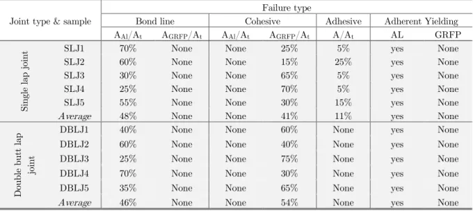
Before final de-bonding of the adherents in all test samples, the aluminum and composite adherents were largely rotated. After fracturing and unloading, a permanent plastic deformation (plastic hinge) was remained for aluminum substrates while the composite was elastically returned to their initial state and no yielding was observed as can be realized in Fig. 11. Table 2 presents the detailed cate-gories of the failure mechanisms of the proposed joints. The percentage ratio of fractured area on substrates to the total bonding area is also calculated.
Figure 11: Plastic deformation on aluminum adherents after de-bonding.
5 CONCLUSIONS
In this paper the load carrying capacity and failure mechanism in adhesive bonding between alumi-num alloy (5083-H32) and glass fiber reinforced composite was evaluated under a standard experi-mental frame work. The effect of joint configuration and dissimilarity of base materials on the
Double butt lap joint Lap joint Plastic deformation
CF CF CF
AFB AFB AFB AFB CF AFB CF
G
F
RP
A
lum
inum
Joint type & sample
Failure type
Bond line Cohesive Adhesive Adherent Yielding AAl/At AGRFP/At AAl/At AGRFP/At A/At AL GRFP
Sin
gle
la
p j
oin
t SLJ1 70% None None 25% 5% yes None
SLJ2 60% None None 15% 25% yes None
SLJ3 30% None None 65% 5% yes None
SLJ4 25% None None 70% 5% yes None
SLJ5 55% None None 30% 15% yes None
Average 48% None None 41% 11% yes None
D
oubl
e but
t l
ap
jo
in
t
DBLJ1 40% None None 60% None yes None
DBLJ2 60% None None 40% None yes None
DBLJ3 25% None None 75% None yes None
DBLJ4 70% None None 30% None yes None
DBLJ5 35% None None 65% None yes None
Average 46% None None 54% None yes None
Table 2: Failure types and ratio of de-bonding areas.
fracture mechanism was analyzed in a single lap and a double butt lap joint. Application of a tough-ened epoxy structural adhesive confirms that this kind of bonding can tolerates high tensile load so that a plastic deformation in aluminum substrates could appear before final fracture which may be a desirable condition in a joint design (i.e. to use the maximum structural capacity of base material before de-bonding).
The results show that a combined failure mechanism could be observed and the most dominant ones for single lap joints were adhesive failure at bond-line on aluminum surface which covers about 48% of bonding area, and yielding of aluminum substrates. For double butt lap joints the dominant failure mechanism were cohesive failure of composite substrate by 54% of bonding area and adhesive failure at bond-line on aluminum surface by 46% of bonding area and yielding of aluminum substrates. No adhesive failure was observed in double butt lap joints while this failure mechanism was observed on 11% of bonding area in single lap joints. This implies that moving from a bond line failure mech-anism to an adhesive failure, would increase the load carrying capacity of a joint which indeed high-lights the importance of surface treatments in an adhesive joint.
Although the single lap joint experiences more bending moment under tensile static load, in com-parison to the double butt lap joint, its energy absorption up to final failure was more and it could withstand loads up to 30% greater than the double butt lap joint. This implies that for increasing the load bearing capacity of an adhesive joint, a special attention should be paid to the flexural and axial rigidity of joint at bonding section by a designer.
Further investigations are necessary to analysis the joint under different type loading and envi-ronmental effects and corrosive conditions.
References
Baldan, A. (2004). Adhesively-bonded joints and repairs in metallic alloys, polymers and composite materials, Journal of Materials Science 39: 1-49.
Baur, P., Roy, A., Casari, P., Choqueuse, D., Davies, P., (2004). Structural mechanical testing of a full size adhesively bonded motorboat. Proceedings of Institution of Mechanical Engineers, part M, Journal of Engineering for the Maritime Environment 218: 226-259.
Cao, J., Grenestedt., J.L., (2004). Design and testing of joints for composite sandwich -steel hybrid ship hulls. Journal Composites 35(9): 1091-1105.
Da Silva, L.F.M., Adams, R., (2006). Stress-free temperature in a mixed-adhesive joint. Journal of Adhesion Science and Technology 20: 1705-1726.
Da Silva, L.F.M., das Neves, P.J.C., Adams, R.D., Spelt, J.K., (2009). Analytical models of adhesively bonded joints part I: literature survey. International Journal of Adhesion and Adhesives 29(3): 319-330.
Di Bella, G., Galtieri, G., Pollicino, E., Borsellino, C., (2013). Mechanical characterization of adhesive joints with dissimila substrates for marine applications. International Journal of Adhesion and Adhesives 41: 33-40.
Diez de Ulzurrun, I., López, F., Herreros, M.A., Suárez, J.C., (2007). Test of deck to hull adhesive joints in GFRP boats. Engineering Failure Analysis 14(2): 310-320.
Gustafson, P.A., Waas, A.M., (2009). The influence of adhesive constitutive parameters in cohesive zone finite element models of adhesively bonded joints. International Journal of Solids and Structures 46: 2201-22015.
Khoshravan, M., Mehrabadi, F.A., (2012). Fracture analysis in adhesive composite/aluminum joints under mode-I loading; experimental and numerical approaches. International Journal of Adhesion and Adhesives 39: 8-14.
Li, H.C.H., Dharmawan, F., Herszberg, I., John, S., (2006). Fracture behaviour of composite maritime T-joints. Com-posite Structures 75: 339-350.
Li, S., Thouless, M.D., Waas, A.M., Schroeder, J.A., Zavattieri, P.D., (2005). Use of a cohesive zone model to analyze the fracture of a fiber-reinforced polymer–matrix composite. Composites Science and Technology 65: 537–49.
Liljedahl, C.D.M., Crocombe, A.D., Wahab, M.A., Ashcroft, I.A., (2006). Damage modelling of adhesively bonded joints. International Journal of Fracture 141: 147-161.
Papini, M., Fernlund, G., Spelt, J.K., (1994). The effect of geometry on the fracture of the adhesive joints. International Journal of Adhesion and Adhesives 14(1): 5-13.
Zhao, B., Lu, Z.-H., Lu, Y.-N., (2011). Closed-form solutions for elastic stress–strain analysis in unbalanced adhesive single-lap joints considering adherend deformations and bond thickness. International Journal of Adhesion and Adhe-sives 31: 434-445.
WeiSgraeber P., Becker, W., (2013). Finite fracture mechanics model for mixed mode fracture in adhesive joints. International Journal of Solids and Structures 50: 2383-2394.