A. F. B. A. Prado
Instituto Nacional de Pesquisas Espaciais INPE-DMC Av. dos Astronautas 1758 Caixa Postal 515 12227-010 São José dos Campos, SP. Brazil [email protected]
Retrograde Orbits Perturbed by a
Third-Body
This paper develops a semi-analytical study of the perturbation caused to a spacecraft by a third body involved in the dynamics. There are several important applications for this research, such as to calculate the effect of lunar and solar perturbations on high-altitude Earth satellites. In the present research the goal is to study the evolution of retrograde orbits around the Earth. There is a special interest to see under which conditions a near-circular orbit remains near-circular. The existence of circular, equatorial and frozen orbits are also considered, The results are valid for any system of primaries by making a time transformation that depends on the masses of the bodies involved. Several plots will show the time-histories of the Keplerian elements of the orbits involved.
Keywords: Astrodynamics, third-body pertutbation, retrograde orbits, space trajectories
Introduction
The majority of papers that considered the third-body perturbation problem studied the perturbation due to the Sun and the Moon in a satellite in orbit around the Earth. Kozai (1959) developed the main secular and long-period terms of the disturbing function due to the lunisolar perturbations in terms of the orbital elements of the satellite, the Sun and the Moon. This research would be later expanded by Musen, Bailie and Upton (1961) to include the parallactic term in the disturbing function. After that, Kozai (1962) studied the problem of secular perturbations in asteroids with high inclination and eccentricity, considering that they are perturbed by Jupiter, which is assumed to be in a circular orbit around the Sun. Blitzer (1959) obtained estimates of the lunisolar disturbances using methods of classical mechanics, however only for the secular terms. In the sequence, Cook (1962) used the Lagrange’s planetary equations to obtain expressions for the variation of elements during a revolution of the satellite and for the rate of variation of the same elements. In that same year, Kaula (1962) derived general terms of the disturbing function for the lunisolar perturbation, using equatorial elements for the Moon, but it didn't supply a definitive algorithm for the calculations. Again Kozai (1965) approached that problem and included indirect terms of the disturbance due to the alteration of the terrestrial flattening due to those forces. 1
In the 1970’s, that subject was studied again. Giacaglia (1973) obtained the disturbing function for the disturbance of the Moon using ecliptic elements for the Moon and equatorial elements for the satellite. Secular, long and short period terms were calculated and expressed in a closed form. Kozai (1973) developed an alternative method for the calculation of the lunisolar disturbances. The disturbing function was expressed in terms of the orbital elements of the satellite and the polar geocentric coordinates of the Sun and the Moon. The secular and long period terms are derived by numerical integration and the short period terms are obtained analytically.
In the following decade, Hough (1981) studied the effects of the lunisolar disturbance in orbits close to the inclinations 63.4° and 116.6° (critical inclinations with respect to the geopotential of the Earth) and concluded that the effects are significant in high altitudes.
All of the preceding references represent fundamental contributions in the subject and they possess an analytic focus, dedicated to the derivation of equations. In the present work a more practical approach is used with the idea of complementing the existent literature. Some recent studies have provided numeric
Paper accepted July, 2005. Technical Editor: Atila P. Silva Freire.
comparisons. In particular, Prado (2002) studied the perturbation in a lunar satellite for direct orbits and the lifetimes of orbits around the natural satellites of the Solar System.
In this paper several topics related to this problem will be studied for retrograde orbits around the Earth, that is an important special case. In particular, the so called "critical angle of the third-body perturbation," which is a value for the inclination such that any near-circular orbit with inclination above this remains near-circular, is discussed in detail. The assumptions of our model are similar to the ones made in the restricted three-body problem: a) There are only three bodies involved in the system: one body with mass m0 fixed at the origin of the reference system; a massless spacecraft in a elliptic three-dimensional orbit around this body and a third body in a circular orbit around this same central body in the plane x-y; b) The motion of the spacecraft is assumed to be a three-dimensional Keplerian orbit with its orbital elements disturbed by the third body. The motion of the spacecraft is studied under the double-averaged analytical model with the disturbing function expanded in Legendre polynomials up to fourth-order. The double-average is taken over the mean motion of the satellite and over the mean motion of the disturbing body. The fact that modern computers can easily integrate numerical trajectories using complex models for the dynamics does not invalidate the use of models based in analytical approximations. The most important reason for this is that a double-averaged model, like the one shown here, can eliminate short-period periodic perturbations that appear in the trajectories. In that way, smooth curves that show the evolution of the mean orbital elements for a long time period can be constructed, which give a better understanding of the physical phenomenon studied and allow the study of long-term stability of the orbits in the presence of disturbances that cause slow changes in the orbital elements. Note that the truncated equations of motion could be numerically integrated much faster than the full equations of the restricted three-body problem. The next sections present: the mathematical model used, the study of circular, near-circular, equatorial and frozen orbits.
The Mathematical Model
(longitude of the ascending node) and the mean motion is n (given
by the expression n2a3=Gm0). In this situation, the disturbing potential that the spacecraft has from the action of the disturbing body is given by:
(
)
( )
S cos ' rr 2 ' r r ' m m G ' R 2 2 0 − + + µ = (1) where ' m m ' m ' 0+ =µ , G is the gravitational constant and S is the
angle between the line that connects the massive central body and the perturbed body (the spacecraft) and the line that connects the massive central body and the perturbing body (the third body).
Using the traditional expansion in Legendre polynomials (assuming that r' >> r) the following expression can be found:
(
)
∑∞(
( )
)
= + µ = 2 n n n0 P cosS
' r r ' r ' m m G ' R (2)
where Pn are the Legendre Polynomials.
For the models used in this research it is necessary to calculate the parts of the disturbing function due to P2, P3 and P4 (R2, R3 and R4, respectively). They are:
[
]
(
( )
)
(
3cos( )
S 1)
a r ' r ' a 2 a ' n ' S cos P ' r r ' r ' m m G ' R 2 2 3 2 2 2 2 0
2 −
µ = + µ
= (3)
[
]
(
( )
)
( )
( )
(
5cos S 3cosS)
a r ' r ' a ' r 2 a ' n ' S cos P ' r r ' r ' m m G ' R 3 3 3 3 2 3 3 0 3 − µ = = + µ = (4)
[
]
(
( )
)
( )
( )
(
35cos S 30cos S 3)
a r ' r 8 ' a a ' n ' S cos P ' r r ' r ' m m G ' R 2 4 4 5 3 4 2 4 4 0 4 + − µ = = + µ = (5)
A substitution using the expression n'2a'3=G
[
m0+m']
was made between the first and the second member of those equations. The next step is to average those quantities over the short period of the satellite as well as with respect to the distant perturbing body. The standard definition for average used in this research is( )
∫π π = 2 0 dM F 2 1F , where M is the mean anomaly, which is proportional to time.
To perform the average over R2, R3 and R4 one proceeds as follows. First define the quantities α=Pˆ.rˆ' and β=Qˆ.rˆ', where
r
'
is the unit vector pointing from the central body to the disturbingbody and Pˆ and Qˆ are the usual orthogonal unit vectors, functions
of (i, ω, Ω), in the plane of the satellite orbit, with Pˆ pointing towards the periapsis. For the special case considered here of circular orbits for the disturbing body the following relations are available:
( ) (
cos M')
cos( ) ( ) (
isin sin M')
cosω Ω− − ω Ω−
=
α (6)
β=−sin
( ) (
ωcosΩ−M')
−cos( ) ( ) (
icosωsinΩ−M')
(7)Using this definition and the geometry involved, it is possible to relate the angle S to the positions of the perturbing and perturbed bodies. This can be made by the equation (where f is the true anomaly of the satellite):
( )
S cos( )
f sin( )
fcos =α +β (8)
Then, combining this equation with equations (3) to (5), the perturbing potential becomes a function of the orbital elements of the satellite. Next, it is necessary to replace the true anomaly (f) by the eccentric anomaly (E). This is made by the well-known relations:sin
( )
f 1 e2sin( )
E(
1−ecos( )
E)
−
= cos
( )
f =(
cos( )
E−e)
(
1−ecos( )
E)
,( )
E cos e 1 ar = − . Then, the integrations required to obtain the averages are realized in terms of the eccentric anomaly, not in terms of the mean anomaly. To do that the relation dM=
(
1−ecos( )
E)
dE is also used. After this process, the following identities appear (Prado, 2002):( )
2 e 4 1 f cos ar2 2 = + 2
, cos
( )
f sin(f) 0 a r 2 = ,( )
2 e 1 f sin ar 2 2
2 − = , 2 e 3 2 a
r 2 + 2
= ,
( )
(
)
8 e 3 4 e 5 f cos ar 3 + 2
− = ,
( )
(
)
8 e 4 3 e 5 f cos ar 3 2
3 + − = ,
( )
f 0sin a r 3 =
, cos
( ) ( )
f sinf 0a
r3 2 =
,
( ) ( )
5e( )
e8 1f sin f cos a
r 2 2
3 − =
, sin
( )
f 0 a r 3 3 = ,( )
(
)
8 e 8 e 12 1 3 f cos ar4 4 = + 2+ 4
, cos
( ) ( )
f sinf 0a
r4 3 =
,
( ) ( )
8 e 6 e 5 1 f sin f cos ar 2 2 2 4
4 − + =
, cos
( ) ( )
f sin f 0a r 3 4 = ,
( )
( )
8 1 e 3 f sin ar 4 2 2
4 − = ,
( )
(
)
8 e 18 e 41 4 f cos ar4 2 = + 2+ 4 ,
( ) ( )
f sinf 0 cos a r 4 = ,( )
8 e 3 e 4 f sin ar 2 2 4
4 − − = , 8 e 15 e 40 8 a
r 4 + 2+ 4
= .
After using those quantities, the expressions (3) to (5) become:
(
)
(
)
β − α + − β + α + µ= 2 2 2 2 2 2
3 2 2 2 4 e 15 1 2 3 e 2 3 1 ' r ' a 2 ' n a '
( )
( )
( )
αβ −
+ + α − + α µ = 8 1 e e 75 8 e 4 3 e 25 8 e 3 4 e 15 ' r ' a ' a 2 ' n a ' R 2 2 2 3 2 4 2 3
3 (10)
(
)
[
(
4 41e 18e)
35(
1 12e 8e)
...10 e 15 e 40 8 ' r 64 a ' n ' a ' 3 R 4 2 4 4 2 2 4 2 5 4 2 3 4 − + + α + + + α − − + + µ =
(
)
(
)
( )
− β + − + β α + − − β−10 24 e2 3e4 70 2 21 5e2 6e4 35 4e2 12
... (11)
Next, one takes the second average with respect to the disturbing body to eliminate the variable M'. To do this, it is necessary to held the Keplerian elements of the spacecraft constant during the process of averaging. This is possible due to the hierarchy of time scales: period of satellite << period of disturbing body << period of slow oscillations in the orbital elements. After making these assumptions the following identities, always valid for circular orbits only, are obtained:
0
2
3 = =
=
α
αβ
α
,( )
( ) ( )
2 sin i cos
cos2 2 2
2 = ω + ω
α ,
( )
( ) ( )
(
)
8 sin i cos cos3 2 2 2 2
4 = ω+ ω
α ,
( )
( )
( )
2 cos i cossin2 2 2
2 = ω + ω
β ,
( ) ( )
( ) ( )
( ) ( ) ( )
... 8 sin cos i cos 4 sin cos 3 cos icos2 4 2 2 2 2 2
2
2β = ω+ ω ω− ω ω +
α
( )
( ) ( )
( ) ( )
8 sin i cos sin cos i cos 3 ... 4 2 2 24 ω ω + ω
+
,
( )
( )
( )
(
)
8 sin cos i cos3 2 2 2 2
4 = ω+ ω
β , a' = r'.
Applying those identities in the expressions (6) to (8), the results are:
( )
(
)
(
( )
)
( )
( )
[
− + − + ω]
=K 23cos i 1 33cos i 1e 15sin ie cos2
R2 1 2 2 2 2 2 (12)
0
R3 = (13)
( )
( )
( )
[
+ + ω+ + ω+ ω]
=K C Ce Ce cos2 Ce Ce cos2 Ce cos4
R4 2 1 2 2 3 2 44 54 6 4 (14)
where: 16 ' n a ' K 2 2
1=µ , 2
4 2 2 ' a 65536 a ' n ' 9
K = µ ,
( )
2i 560cos( )
4i cos320 144
C1= + + , C2=5C1,
( )
2i 3920cos( )
4i cos2240 1680
C3= + − ,
2 C C , C 8 15
C4= 1 5= 3,
( )
2i 1470cos( )
4icos 5880 4410
C6= − + ,
The partial derivatives required for the equations of motion are:
( )
(
)
(
( )
)
( )
( )
[
− + − + ω]
µ = ∂ ∂ 2 cos e i sin 15 e 1 i cos 3 3 1 i cos 3 2 8 ' an ' a
R2 2 2 2 2 2 2 (15)
=
[
(
( )
−)
+( )
( )
ω]
∂ ∂ 2 cos e i sin 5 e 1 i cos 3 K 6 e
R 2 2
1
2 (16)
=
[
−( )
−( )
+( )
( )
ω]
∂ ∂ 2 cos e i 2 sin 5 e i 2 sin 3 i 2 sin 2 K 3 i
R 2 2
1
2 (17)
( )
( )
ω− = ω ∂ ∂ 2 sin e i sin 30 K
R 2 2
1
2 (18)
( ) ( ) ( )
[
+ + ω+ + ω+ ω]
µ = ∂ ∂ 4 cos e C 2 cos e C e C 2 cos e C e C C ' a 16384 a ' n ' 9 a R 4 6 4 5 4 4 2 3 2 2 1 2 3 2 4 (19)
( )
( )
( )
ω + ω + + ω + = ∂ ∂ 4 cos e C 2 2 cos e C e C 4 15 2 cos e C e C 5 K 2 e R 3 6 3 3 3 1 3 1 2 4 (20)( )
( )
( )
[
+ + + ω+ ω+ ω]
= ∂ ∂ 4 cos e C 2 cos e C 2 cos e C e C e C C K i R 4 12 4 11 2 10 4 9 2 8 7 2 4 (21)
=−
[
( )
ω +( )
ω+( )
ω]
ω ∂ ∂ 4 sin e C 4 2 sin e C 2 sin e C 2 K R 4 6 4 3 2 3 2 4 (22) where:
( )
2i 2240sin( )
4i sin640
C7=− − ,
( )
2i 11200sin( )
4i sin3200
C8=− − ,
( )
2i 4200sin( )
4i sin1200
C9=− −
( )
2i 15680sin( )
4i sin4480
C10=− + ,
( )
2i 7840sin( )
4i sin2240
C11=− + ,
( )
2i 5880sin( )
4i sin11760
C12= −
The next step is to obtain the equations of motion of the spacecraft. They come from the Lagrange's planetary equations in the form that depends on the derivatives of the disturbing function R with respect to the Keplerian elements.
0 dt da
= (23)
(
ω)
+ ω −
µ
= sin (i)sin(2 ) f a,e,i,
n 8 e 1 e ' n ' 15 dt de 1 2 2 2 (24)
(
ω)
+ ω −
µ −
= sin(2i)sin(2 ) f a,e,i,
e 1 n 16 e ' n ' 15 dt di 2 2 2 2 (25)
[
− + + − − ω]
+(
ω)
− µ = ω , i , e , a f ) 2 cos( ) i cos e 1 ( 5 ) e 1 i cos 5 ( e 1 n 8 ' n ' 3 dt d 3 2 2 2 2 2 2 (26)
[
ω − −]
+(
ω)
− µ = Ω , i , e , a f 2 e 3 ) 2 cos( e 5 e 1 n 8 i cos ' n ' 3 dt d 4 2 2 2 2 (27)
[
+ − + + ω]
+(
ω)
µ −
= (3e 7)(3cos i 1) 15(1 e )sin icos f a,e,i, n 8 ' n ' dt dM 5 2 2 2 2 2 2
0 (28)
where fi
(
a,e,i,ω)
represents the contribution of the fourth-order term and they are given by:(
)
( )
( )
( )
[
ω + ω + ω]
(
)
( )
( )
( )
( )
( )
[
ω+ ω+ ω]
− µ − = ω
4 sin e C 4 2 sin e C 2 sin e C 2
i sin n ' a 65536 e 1
i cos a ' n ' 9 ,
i , e , a f
4 6 4
3 2
3
2 2
2 2 2
(30)
(
)
( )
( )
( )
( )
( )
( )
( )
( )
[
+ + + ω + ω + ω]
− µ −
ω +
ω +
+ ω +
− µ
= ω
4 cos e C 2 cos e C 2 cos e C e C e C C
i sin n ' a 65536 e 1
i cos a ' n ' 9
4 cos e C 2 2 cos e C e C 4 15 2 cos C C 5
n ' a 32768
e 1 a ' n ' 9 , i , e , a f
4 12 4
11 2
10 4 9 2 8 7
2 2
2 2
2 6 2
3 2 1 3
1
2 2 2 2 3
(31)
(
)
( )
( )
( )
( )
[
+ + + ω + ω + ω]
− µ =
ω
4 cos e C 2 cos e C 2 cos e C e C e C C
i sin n ' a 65536 e 1
a ' n ' 9 ,
i , e , a f
4 12 4
11 2
10 4 9 2 8 7
2 2
2 2 4
(32)
(
)
( )
( )
( )
( )
( )
( )
( )
[
+ + ω+ + ω+ ω]
µ −
ω +
ω +
+ ω +
− µ − = ω
4 cos e C 2 cos e C e C 2 cos e C e C C
n ' a 8192
a ' n ' 9
4 cos e C 2 2 cos e C e C 4 15 2 cos C C 5
n ' a 32768
e 1 a ' n ' 9 , i , e , a f
4 6 4
5 4 4 2
3 2 2 1
2 2 2
2 6 2
3 2 1 3
1
2 2 2 2 5
(33)
There are some conclusions that come directly from the equations of motion: i) the term µ’ is a constant that multiplies all the equations of motion, so it is equivalent to a time transformation in the system of the type µ’t = t*. So, all the results based in those equations are valid for any system of primaries in a proportional time scale. The same is true for the semi-major axis (that is present in the equations in the term “n”) in the second-order model; ii) the
ratio
2 2
2 1
a ' a 4096 K
K =
gives an idea of the relative importance of the
second and fourth-order terms. The importance of the fourth-order terms increase when the semi-major axis of the perturbed body increases. This importance also increases with the eccentricity of the perturbed body due to the terms that depend on the eccentricity; iii) The difference between the analytical solutions and the full numerical simulations also increases with those variables, what is confirmed by numerical integrations and by the fact that the expansions are made in terms of the eccentricity.
Results
In this section some results are shown related to the third body perturbation problem for retrograde orbits. This section is divided in several sub-sections to show clearly several aspects of the problem.
The Circular Orbits and the Critical Inclination
Directly from the equations of motion for the averaged models it is possible to identify the existence of circular solutions for both second and fourth-order models. It means that, in the ideal case of an orbit that starts with zero eccentricity, its eccentricity remains always zero. This occurs because the right-hand side of the equation for the time derivative of the eccentricity is zero (it is a polynomial in the eccentricity with no independent term). Another property of those orbits is that the inclination is also constant for the same
reason, since the time derivative of the inclination is also a polynomial in the eccentricity with no independent term.
The evolutions of these two quantities (eccentricity and inclination) are studied under the full restricted three-body problem. The results show that the circular solutions with constant inclination do not exist in this more realistic model. The eccentricity oscillates with large amplitude. The inclination remains close to constant most of the time, but from time to time it goes to the value of the critical inclination and then it returns to its initial value. This behavior is similar to the near-circular orbits shown in Figs. 1 to 3. This result is expected, because there is no physical reason to have a strong difference in the behavior of orbits with eccentricity 0.00 and 0.01. The general conclusion is that the circular solutions with constant inclination appear due to the truncation of the Legendre polynomial and are not a physical phenomenon, at least for the conditions simulated in this research.
Another important question in this problem is the existence of a critical value for the inclination between the perturbed and the perturbing bodies. This critical inclination is related to the stability of near-circular retrograde orbits. The problem is to find under what conditions a spacecraft that starts in a near-circular retrograde orbit around the main body remains in a near-circular orbit after some time. The answer for this question depends on the initial inclination i0. There is a specific critical value such that if the inclination is lower than that the eccentricity increases and the near-circular orbit becomes very elliptic. Alternatively, if the inclination is higher than this critical value the orbit stays nearly circular. So, only retrograde orbits with inclination higher than that are useful for practical purposes. The problem of near-circular orbits is very important because usually a spacecraft that is nominally in circular orbit experiences perturbations from other sources that make its eccentricity become non-zero. In the double-averaged second-order
0 20000 40000 60000
Time (Canonical Units)
1.6 1.8 2.0 2.2 2.4 2.6
In
cl
in
at
io
n
(
R
ad
)
0 20000 40000 60000
Time (Canonical Units)
2.44 2.46 2.48 2.50 2.52 2.54
In
cl
in
at
io
n
(
R
ad
)
0 20000 40000 60000
Time (Canonical Units)
2.6 2.7 2.8 2.9 3.0 3.1
In
cl
in
at
io
n
(
R
ad
)
Figure 1. Time-histories for the inclination.
0 20000 40000 60000
Time (Canonical Units)
0.0 0.2 0.4 0.6 0.8 1.0
E
cc
en
tr
ic
it
y
i=120 i=110 i=100 i=90
i=130
i=140
0 20000 40000 60000
Time (Canonical Units)
0.00 0.04 0.08 0.12 0.16 0.20
E
cc
en
tr
ic
it
y
i=140
i=141
i=142
i=143
i=144
0 20000 40000 60000
Time (Canonical Units) 0.008
0.010 0.012 0.014 0.016 0.018
E
cc
en
tr
ic
it
y i=150
i=160
i=170 i=180
Figure 2. Time-histories for the eccentricity.
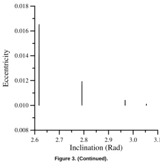
increases with i0. The inclination has a very characteristic behavior in this region of i0. For values of i0 slightly above the critical angle the inclination stays close to i0. For values of i0 slightly below the critical value the inclination starts at i0, increases until the critical value and then it returns to its original value i0. Those results show that the critical angle is not a sharp separation between stable and unstable near-circular retrograde orbits. For values of i0 well below the critical value (i0 < 130°) the eccentricity oscillates with increasing amplitudes that go close to 1.0. The inclination keeps its characteristic behavior of starting at i0, increasing to the critical value and then returning to its original value i0. The figure also shows that this behavior repeats itself in an endless cycle. The time required to reach the critical value increases when i0 increases. This region has a gradual transition where the eccentricity oscillates with an amplitude that increases fast with i0, reaching the value 1.0 only in the case i0 = 90°. Fig. 3 shows the results in the phase diagram that plots the eccentricity vs. the inclination. The region above the critical value shows straight lines. Note that the different scales of the plots show different aspects of the comparison.
1.6 1.8 2.0 2.2 2.4 2.6
Inclination (Rad)
0.0 0.2 0.4 0.6 0.8 1.0
E
cc
en
tr
ic
it
y
2.44 2.46 2.48 2.50 2.52 2.54
Inclination (Rad)
0.00 0.04 0.08 0.12 0.16 0.20
E
cc
en
tr
ic
it
y
Figure 3. Inclination and Eccentricity in the i-e plane.
2.6 2.7 2.8 2.9 3.0 3.1
Inclination (Rad)
0.008 0.010 0.012 0.014 0.016 0.018
E
cc
en
tr
ic
it
y
Figure 3. (Continued).
It is possible to understand those behaviors by examining the second-order equations of motion, since the comparisons showed that this model adequately represents the system. The magnitude of the time derivative of the eccentricity is dependent on the term
2 e 1
e − , so it increases when the eccentricity has lower values due to the presence of e, but after a value close to 0.71 is reached, it
starts to decrease due to the term 1−e2 . Its sign is determined exclusively by sin(ω) and it imposes the oscillatory behavior shown in the plots, since ω has a secular variation. For the time derivative of the inclination the same analysis can be applied. The magnitude
is influenced by the term e2 1−e2 , which causes the curious behavior of showing regions of almost constant inclination alternated with sharp decreases and increases. The explanation is
that for lower values of the eccentricity the term e2 forces the time derivative to stay close to zero and the inclination remains almost constant. When the eccentricity increases and reaches values close
to 1.0, the term 1−e2 present in the denominator forces the time derivative to increase fast, tending to infinity, which causes the fast motion of the inclination. The alternation of the sign is caused exclusively by the term sin(ω), as explained before. The argument of periapsis has a secular variation, because its time derivative is always positive in the situations considered, alternating large regions of slow and short regions of fast increases. The fast increase
is also explained by the term 1−e2 in the denominator that goes close to zero when the eccentricity approaches 1.0.
The practical application of those results is that only near-circular orbits with inclination higher than the critical value are stable in the long range, since above this value the orbit looses its characteristics of near-circularity.
The Equatorial Orbits
the right-hand sides of the expressions for dt de
and dt di
are also zero,
because they are proportional to sin2(i) and sin(2i), respectively. For the fourth-order model, the expression for the time derivative for the inclination has a singularity, due to the sin(i) present in the denominator. The expression for the time derivative of the eccentricity is not zero, because the coefficients C3 and C6 that
appear in the equation for f1
(
a,e,i,ω)
, do not vanish when the inclination is zero. The numerical integration of the full restricted three-body problem model shows the existence of equatorial solutions (zero inclination all the time) also in this more general model, as expected due to the symmetry of the system. But, opposite to the second-order model, the eccentricity has short-period oscillations with an amplitude that depends on the initial eccentricity, but it can reach values large enough to destroy completely the circularity of the orbits.Frozen Orbits
From the equations of motion for the second-order model it is possible to detect the existence of a family of special orbits that have constant semi-major axis, eccentricity, inclination and argument of periapsis called "frozen orbits." To obtain this family it is necessary to find the solutions of the equations:
de dt
di dt
d dt
= = ω=0, since the time derivative for the semi-major axis is always zero. To satisfy the equation for the time derivative of the eccentricity the condition is sin(2ω) = 0, which implies that cos(2ω) = ±1. Analyzing the solution cos(2ω) = +1 in the equation for the time derivative of the argument of periapsis, it is seen that its only possible solution is e = 1.0. So, only the solution cos(2ω) = -1 is taken and it implies that ω = 90° or ω = 270°. The vanishing of the time derivative for the inclination does not add any new condition, since sin(2ω) = 0 used above implies in di/dt = 0. From
the equation 0 dt
dω= and the assumed solution cos(2ω) = -1 one
more condition is found:
(
− −)
= ⇒− +
−1 e 51 e cos (i) 0
) i ( cos
5 2 2 2 2 cos(i)
3 5 1 e
2= − 2 (34)
This is a relation between the eccentricity and the inclination that allows frozen orbits. From this equation the condition
5 3 ) i (
cos2 < is also obtained. This condition sets a minimum value for the inclination, that is the critical value discussed before, due to
the restriction
e
2 > 0. Those conditions are valid only for the second-order model. When submitted to the fourth-order and to the full restricted problem model a frozen orbit is destroyed and it shows periodic oscillations in all the three orbital elements. The difference between the fourth-order and the restricted models are in the amplitude of the oscillations. The amplitudes are about ten times larger when the restricted problem is used. As an example, the frozen orbit with eccentricity 0.3 and inclination 137.63934 degrees was simulated and the oscillations for the fourth-order model were: 0.01 rad in inclination, 0.03 in eccentricity and 0.08 rad in the argument of periapsis. For the restricted model the oscillations were: 0.14 rad in inclination, 0.3 in eccentricity and the argument of periapsis assumed all values in the interval [0,2π] rad. Examining the equations of motion for the fourth-order model, it is seen that(
a,e,i,ω)
f1 = f2
(
a,e,i,ω)
= 0, but f3(
a,e,i,ω)
≠ 0. It means that the eccentricity and the inclination keep their time derivatives null for the fourth-order model. The destruction of the frozen orbitscomes from the argument of periapsis, because its time derivative is not null, so the argument of periapsis deviates from the frozen condition, which makes sin(2ω) ≠ 0 and it implies that all the time derivatives deviate from zero. Another application of the frozen orbits in the second-order model is to test the accuracy of the numerical integration of this model.
Effects of the Semi-Major Axis
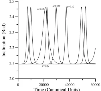
The next step is to study the effects of the initial semi-major axis in the behaviour of the trajectories. Figure 4 shows the variation in the inclination for trajectories starting with initial inclination equals to 120 degrees and semi-major axis assuming the values 0.02, 0.06, 0.10, 0.12 and Fig. 5 shows the evolution of the eccentricity for the same trajectories.
0 20000 40000 60000
Time (Canonical Units)
2.0 2.1 2.2 2.3 2.4 2.5
In
cl
in
at
io
n
(
R
ad
)
a=0.06 a=0.12
a=0.02 a=0.10
Figure 4. Effects of the semi-major axis in the inclination of the trajectories.
0 20000 40000 60000
Time (Canonical units)
0.0 0.2 0.4 0.6 0.8
E
cc
en
tr
ic
it
y
a=0.02 a=0.6
a=1.0 a=1.2
Conclusions
This paper develops a mathematical model to study the third-body perturbation in a retrograde orbit: the double-averaged expanded to the fourth-order in Legendre polynomials. The results show in detail the behavior of retrograde orbits with respect to its initial inclination and the role of the critical inclination in the stability of near-circular orbits. They show that this critical value is a transition region where the eccentricity has an oscillation that increases in amplitude. It has also shown the existence of equatorial solutions (but with the eccentricity oscillating) and the non-existence of circular solutions under the dynamics given by the restricted three-body problem. The "frozen orbits" found in the double-averaged second-order model are studied in the fourth-order and the full restricted models. It is shown that they have their Keplerian elements disturbed by a small periodic oscillation in the fourth-order model and a large periodic oscillation in the restricted problem.
Acknowledgment
The author is grateful to CNPq (National Council for Scientific and Technological Development) - Brazil for the contract 300221/95-9 and to FAPESP (Foundation to Support Research in São Paulo State) for the contract 2000/14769-4. The author also acknowledges Roger Broucke, whose class notes provided the basis for the double-averaging method.
References
Blitzer, L., 1959, “Lunar-Solar Perturbations of an Earth Satellite,” American Journal of Physics, Vol. 27, No. 9, pp. 634-645.
Cook, G. E., 1962, “Luni-Solar Perturbations of the Orbit of an Earth Satellite,” The Geophysical Journal, Vol. 6, No. 3, pp. 271-291.
Giacaglia, G. E. O., 1973, “Lunar Perturbations of Artificial Satellites of the Earth,” Smithsonian Astrophysical Observatory, Special Report 352, Cambridge, MA..
Hough, M.E., 1981, “Orbits Near Critical Inclination, Including Lunisolar Perturbations,” Celestial Mechanics, Vol. 25, No. 2, pp. 111-136.
Kaula, M. W., 1962, “Development of the Lunar and Solar Disturbing Functions for a Close Satellite,” Astronautical Journal, Vol. 67, pg. 300.
Kozai, Y., 1959, “On the Effects of the Sun and the Moon upon the Motion of a Close Earth Satellite,” Smithsonian Astrophysical Observatory, Special Report 22, Cambridge, MA..
Kozai, Y., 1962, “Secular Perturbations of Asteroids with High Inclination and Eccentricity,” The Astronomical Journal, Vol. 67, No. 9, pp. 591-598.
Kozai, Y., 1965, “Effects of the Tidal Deformation on the Motion of Satellites,” Publications of the Astronomical Society of Japan, Vol. 17, pp. 395-402.
Kozai, Y., 1973, “A New Method to Compute Lunisolar Perturbations in Satellite Motions,” Smithsonian Astrophysical Observatory, Special Report 349, Cambridge, MA..
Musen, P., Bailie, A., and Upton, E, 1961, “Development of the Lunar and Solar Perturbations in the Motion of an Artificial Satellite,” NASA-TN, D494.