A FUZZY BASED POWER QUALITY
ENHANCEMENT STRATEGY FOR
AC-AC CONVERTERS
N.Radhakrishnan* M.Ramaswamy
Lecturer Professor
Department of Electrical Engineering,
Annamalai University, Annamalai nagar, TamilNadu-608002. ABSTRACT
This paper attempts to design a fuzzy controller, with a view to enhance the overall power quality of an ac-ac converter and regulate the load voltage. Besides it envisages to investigate the performance of three firing strategies for the power switches in an AC–AC Converter. The algorithm is articulated in order that the input current vector is allowed to closely follow the source voltage wave such that there is an enhancement in the fundamental component, while the other harmonic components are significantly reduced. It presents Matlab based simulation results to demonstrate the comparative merits of the triggering schemes and highlight the suitability of the fuzzy logic controller over a wide range of load variations.
KEY WORDS: AC-AC Converter, Fuzzy Control, Power Quality, Voltage Regulation.
INTRODUCTION
AC voltage regulators are traditionally used to control power ranging from a few watts to fractions of megawatts. The repeated switching action of the semiconductor devices in the power converter generates higher order harmonics at the output. The input voltage distortion in the converter limits the amplitude of the fundamental and introduces undesired harmonic components. The use of conventional harmonic reduction techniques ends up only with the reappearance of the lower order harmonics in the output waveform. Besides larger the angle of advance, poorer is the converter utilization and greater is the reactive power consumed.
Phase-angle and integral-cycle controlled line commutated voltage controllers have been extensively employed. Though such techniques posses the ability of controlling large amount of power economically, it has been to found to suffer from inherent disadvantages such as retardation of the firing angle resulting in a lagging power factor at the input side especially at large firing angles and contaminating the current with high lower order harmonic content in both load and supply sides. [1-3].
A modified phase angle strategy, built with a desired relationship between the output and input voltage has been found to yield a higher fundamental component. Forced commutation realized through the use of a free wheeling diode is implemented in an attempt to improve the input power factor of the ac voltage controller. The performance evaluation of the EAC technique on a Single Phase Voltage Controller has been illustrated through static load and the widely used Single-Phase Induction Motor to verify the feasibility of the proposed approach [4]. Owing to the fact that these techniques have not been successful in controlling the harmonics, later developments have been found to pave the way for the emergence of symmetrical angle control (SAC), asymmetrical angle control (AAC) and high frequency time ratio control (TRC), in an effort to reduce the harmonics.
PROBLEM DESCRIPTION
The objective is to design a fuzzy controller that envisages to reduce the harmonic content and improve the overall power quality of an ac-ac conversion system. The performance of Power Converters depend to a large extent on the suitability of the control technique used to generate the firing pulses for the power switches, which in turn serve to control the power as desired by the application. It is this prelude that the suitability of three different schemes is investigated with an AC-AC Converter to decide the choice of a particular scheme for a chosen application.
FUZZY ALGORITHM
Fuzzy logic has found its role in many interesting application owing to the fact that it does not require a complete mathematical model. The philosophy of fuzzy is a theory about vagueness or uncertainty and enables the use of non-precise, ill-defined concepts. The significant feature is that it generates better solutions that cannot be determined by other methods. It employs linguistic terms with casual relationship between the input and output variables because of which it is easy to manipulate and rig out solutions.
The fuzzy terms describing both the input identified variables error (e), change in error (ce) and the output variable (u) are negative big (NB), negative medium (NM), negative small (NS), zero (ZO), positive small (PS), positive medium (PM) and positive big (PB). The sets defining the e, ce and u are as follows:
e = {NB, NM, NS, ZO, PS, PM, PB} ce = {NB, NM, NS, ZO, PS, PM, PB} u = {NB, NM, NS, ZO, PS, PM, PB}
Triangular membership functions with the specified range of values are chosen for input and output linguistic variables. The variables are fuzzified through a continuous universe of discourse method and Mamdani’s minimum operator implication is used. The fuzzy results are defuzzified through a centroid defuzzification process, in order to achieve a crisp numerical value.
RULE BASE
The decisions are made by forming a series of rules that relate the input variable to the output variable
through “IF-THEN” statements. The input fuzzy variable is the output voltage, for which ‘e’ and ‘ce’ are computed. These decision rules are expressed using linguistic variables. For example, a typical rule reads as follows:Rule 1: If e is NS and ce is PS, THEN u is ZO Rule 2: If e is PS and ce is PB, THEN u is PB
A set of fuzzy rules similar to the above can be obtained for different ‘e’ and ‘ce’ values. The algorithm serves to determine the output, the control action ‘u’ which generates the reference wave.
PROPOSED APPROACH
The power circuit of the single phase 230V, 50Hz ac-ac converter shown in Fig.1 consists of two bidirectional switches, with an IGBT in each of the legs of a diode bridge. One of them serves to regulate the power delivered to the load rated for 6 KW, while the other is used in the freewheeling path. The approach includes to generate pulses for the power switches in Fig.1 through a fuzzy based EAC and PWM schemes. The role of fuzzy is to create a search mechanism and obtain an appropriate EAC/PWM pulses.
Fig.1 Power Circuit
EXTINCTION ANGLE CONTROL (EAC)
is allowed to start at the zero crossing of the supply voltage and the switch is forced to commutate at ωt = π−β. A
freewheeling path is provided for the load current to discharge the stored energy of the load inductance. The output voltage is controlled by varying the extinction angle β. The fundamental component of the input current therefore leads the input voltage, and the displacement factor (and power factor) is improved considerably.
The switching state is reversed when π– α < ωt < π. The switching state in the negative half cycle of supply
voltage is same as in positive one. So, the frequency of the switching function is double the supply frequency. The rms component of the fundamental output phase voltage is:
sin
(
)
(
)
sin
2
2
2 2
1
m r
V
V
It is clear that the fundamental component of the output voltage is inversely proportional to the value of angle α. The angle between the fundamental component of the output voltage and the supply voltage,
1 is given by:
sin
sin
*
2
tan
2
tan
1 1 PWM SCHEMEThe most widely used strategy for controlling the power output of a Power Converter is the technique known as Pulse Width Modulation (PWM). A modulation scheme aims to create trains of switched pulses which have the same fundamental volt-second average (i.e. the integral of voltage waveform over time) as a target reference waveform at any instant. The main aim of any PWM scheme is to calculate the converter switch ON times which offer the desired target output voltage or current and determine the most effective way of arranging the switching processes to minimize unwanted harmonic distortion.
Among a number of available schemes, Sinusoidal Pulse Width Modulation (SPWM) and Random PWM (RPWM) are preferred on account of their flexibility and ease of implementation. The general principle of SPWM is that an isosceles triangle carrier wave of frequency “fc” is compared with the sinusoidal fundamental modulating wave of frequency “f” and the points of
intersection determine the switching points of power device.
The RPWM technique is a novel method that serves to distribute the power spectrum of noise over a wide frequency range and reduce the amplitudes of high frequency harmonics. Randomization of the switching frequency is the most common implementation of RPWM. The triangular carrier signal, with which the reference voltage signal is compared, is generated
with a random slope.
Fig.2 Block diagram
SIMULATION RESULTS
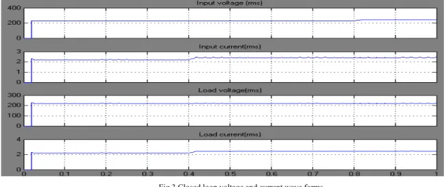
The scheme is simulated using MATLAB–SIMULINK. The source rms voltage, input current, rms load voltage and load current waveforms corresponding to a load of 4KW, obtained using SPWM is depicted in Fig 3. Step changes in supply and load are introduced independently and their results displayed in the same figure.
Fig.3 Closed loop voltage and current wave forms
The sudden increase in load at 0.4 sec is accompanied by a proportionate increase in the load current. Though the load voltage attempts to decline, it is almost instantaneously corrected by the action of controller in the feedback path. A similar effect is observed at 0.8 sec when a sudden change occurs in the supply. Thus the FLC enables the Power Converter to exhibit the desired performance even in the event of occurrence of such disturbances.
The input current Power Quality indices of the schematic under study for three firing schemes is tabulated in Table 1 for a range of load powers allowed to vary from 3.5 to 6 KW. The frequency spectra for a load power of 4 KW is depicted in Fig. 4
Table 1. Closed loop performance comparison
SPWM is superior in its attempt to minimize the harmonics in the sense it offers the minimum THD and enables to draw the highest fundamental input current. The FLC on its part contributes to further enhance the fundamental and still lower the THD. The specific advantage of RPWM as seen from the harmonic spectrum in Fig. 4(c) is that it facilitates to spread the harmonic power such that no harmonic component has a dominant value, and the FLC in its bid sustain the spectra.
Fig.4a) Spectra for EAC
Fig.4b) Spectra for SPWM
Fig.4c) Spectra for RPWM
The variation of input current power factor with load power obtained through EAC for both PI and Fuzzy controllers is related through bar chart in Fig 5. A similar chart exhibiting the variation of THD with load power in the case of SPWM is shown in Fig 6. The diagrams in addition to validating the Fuzzy results serves to point out that FLC outperforms the traditional controller owing to its logical nature and reasoning capability.
0.97 0.975 0.98 0.985 0.99 0.995
P
o
w
er
f
act
o
r
3.5 4 4.5 5 5.5 6
Loadpower(KW)
FUZZY PI
0 2 4 6 8 10 12 14
TH
D
%
3.5 4 4.5 5 5.5 6
Loadpower(KW)
FUZZY PI
Fig.5 Load vs PF [EAC]
Fig.6 Load vs THD% [SPWM]
CONCLUSION
validated through PI action has been found to prove worthy for use with Power Converters. The performance of three firing schemes has been compared to highlight the advantages of the individual method. The fact that SPWM inherits a number of specific advantages has been amply brought out to illustrate its applicability over a wide range of applications. The ability of RPWM to spread its harmonic power has been found to tailor itself to be suitable for high power applications on account of the fact that it significantly curtails the magnitude of harmonic components besides reducing the filtering requirements. Though the choice of a particular scheme can only be decided by specific needs still such an analysis along with the merits of the proposed FLC will go a long way in nurturing innovative applications for AC-AC conversion systems.
REFERENCES
[1] E.El-Bidweihy, et.al, “Power Factor of AC controllers for inductive loads”, Trans. on IECI, vol.27, no.3, 1980.
[2] K.A.Krishnamurthy, et.al, “Ac power control of an RL load”, IEEE Trans. Ind. Electron. Contr. Instrum., vol.28, no.4, 1981.
[3] S. Willliams, "Reduction of the Voltage and Current Harmonics Introduced by a Single-Phase Triac ac Controller," IEEE Trans. Ind. Electron. Contr. Instrum. Vol. 28, no. 4, 1981.
[4] Nabil A. Ahmed, Emad H. El-Zohri, “Power factor improvement of single_phase ac voltage Controller employing extinction angle Control technique”, IEEE., pp. 1075-1080, 2004.
[5] Gyu-Ha Choe, et.al., “A new pulse width modulated method for ac chopper”, IEEE Power Electronics Specialists Conf. Rec., 1987. [6] K.E.Addoweesh and A.L.Mohamadein, “Microprocessor Based Harmonic Elimination in Chopper Type AC Voltage Regulators”, IEEE
Trans. Power Elec., vol.5, no.2, pp.191-200, April 1990.
[7] P.N.Enjeti, P.D.Ziogas and J.F.Lindsay, “Programmed PWM technique to Eliminate Harmonics: A Critical Evaluation”, IEEE Trans. Ind. Appl., vol.26, no.2, pp.302-316, March/April 1990.
[8] Lin, B.R, Hung, T.L, Huang, C.H, “Single-phase AC/AC converter with capacitor-clamped scheme’, IEE Proceedings on Electric Power Applications, Vol.150, Issue 4, 8, Page(s): 464 – 470, July 2003
[9] Kawai Makoto, Ueda Akiteru, Torii Akihiro, Doki Kae, “Control Characteristic of Buck-boost AC Chopper”, IEE Papers of Technical Meeting on Semiconductor Power Converter, Japan,vol.SPC-04, no.74-92, page.93-98, 2004.
[10] Rahmani L., Krim F., Khanniche M. S., Bouafia A., “Control for PWM ac chopper feeding nonlinear loads”, International journal of electronics, vol. 91, no.3, pp. 149-163, 2004.
[11] Tanimatsu Hiroaki, Hiraki Eiji, Tanaka Toshihiko, Nakaoka Mutsuo, Yasui Kenji, Hirota Izuo, Iwai Toshiaki, Omori Hideki, “One Stage High Frequency AC-AC Converter for Induction Heating with Power Factor Correction Function”, IEE Papers of Technical Meeting on Semiconductor Power Converter, Japan vol.SPC-06;no.36-42.44-47; page. 47-52, 2006.
[12] Fang Lin Luo; Hong Ye, “DC-Modulated Power Factor Correction on AC/AC Luo-Converter”, 9th International Conference on Control, Automation, Robotics and Vision, Volume, Issue , 5-8 Page(s):1 – 6, Dec. 2006.
[13] Kirubakaran.D, Rama Reddy.S., “Closed Loop Controlled AC-AC Converter for Induction Heating”, Journal of Industrial Technology, Volume 25, Number 2, June 2009.
[14] Garg.V, Singh.B and Bhuvaneswari.G., “24-pulse ac–dc converter for harmonic mitigation”, IET Power Electronics, Volume 2, Issue 4, p.364–374, July 2009.
[15] Maswood A.I. and Firmansyah.E, “Current injection in a controlled rectifier under unbalanced supply and variable line and load inductances”, IET Power Electronics, Volume 2, Issue 4, p.387–397, July 2009.
ACKNOWLEDGEMENT