Advances in Mechanical Engineering 2015, Vol. 7(9) 1–9
ÓThe Author(s) 2015 DOI: 10.1177/1687814015605009 aime.sagepub.com
Structure design and kinematics
simulation of a novel arm-type single
stereo parking lot
Dongliang Chu
1, Qing He
1, Daqing Zhang
2and Xinhua Mao
1Abstract
Space-saving, high-density stereo parking lots have gained considerable attention because of emerging limitations in ground and underground space. In this article, a novel arm-type single stereo parking lot is proposed to realize conveni-ence and environmental friendliness. Many technical difficulties should be resolved before the safety performance of the stereo parking lot can be enhanced. Therefore, the structural characteristics, the load state and the motion situation should be analysed by numerical simulation to develop a reasonable design scheme. Finite element analysis was con-ducted on the steel tray platform, and kinematic analysis was performed on the end of novel arm-type single stereo parking lot. As a result, the position, velocity and acceleration curves as well as the maximum workspace were demon-strated by simulation in Pro/E. The simulation results demonstrate the correctness and accuracy of the stereo parking lot under motion mode feasible in residential areas and agency units and that the proposed parking lot can become pop-ular in practice because of characteristics such as simplicity, convenience, easy development and promotion.
Keywords
Mechanical design, modelling, finite element analysis, kinematics, simulation
Date received: 15 May 2015; accepted: 3 August 2015
Academic Editor: Yong Chen
Introduction
Recent urbanization and economic development have led to a boom in the automobile industry, resulting in a sharp rise in static traffic problems, that is, parking problems.1,2For example, from 1978 to 2002, the num-ber of privately owned cars increased by approximately 20 times. The number of vehicles in operation world-wide surpassed the 1 billion-unit mark in 2010 for the first time ever. Therefore, parking lots have become an important object class in many applications. In view of the limitations of ground and underground space, space-saving, high-density stereo parking lots have gained considerable interest as a research target.
As a kind of robot, the kinematics study of the park-ing lot is necessary. Robot kinematics describes the changes in the joint and the end executor during the
process of robot movement, which is the basis of robotics. Kinematics is generally categorized into two aspects: forward kinematics and inverse kinematics.1–4 Forward kinematics is the process of finding the posi-tion and posture of the end executor of the robot after the parameters of the connecting rods and the variables of the joint are obtained. In contrast, inverse kinematics involves solving the joint variables of the robot on the
1School of Energy Power and Mechanical Engineering, North China Electric Power University, Beijing, P.R. China
2Department of Mechanical Engineering, North China Electric Power University, Baoding, P.R. China
Corresponding author:
Dongliang Chu, School of Energy Power and Mechanical Engineering, North China Electric Power University, Beijing 102206, P.R. China. Email: [email protected]
basis of the known position and posture of the end actuator. In robot kinematics research, homogeneous transformation matrix is commonly adopted to describe the relationship between adjacent connecting rods and subsequently establish the kinematics equation.
According to previous studies, the inverse solution of the kinematics of the parking lot can be determined by many different ways, including geometric method, iterative method, analytical method and the combina-tion of these methods. The geometric method is suit-able for kinematics analysis with simple structure, less degrees of freedom and obvious geometrical relation-ship among the agencies. Iterative method is charac-terized by a relatively large amount of calculation, slow calculation speed and low accuracy, which are the factors that influence the control requirements of the robot. Analytical method was established based on the robot kinematics equation. Both sides of the equation are then multiplied with the inverse matrix of the homogeneous transformation matrix between the adjacent connecting rod. Finally, the required joint variable is isolated according to the equality of the corresponding matrix elements on both sides of the equation.
Trajectory planning is the fundamental step of bot-tom of the planning, and it is based on the kinematics and dynamics of the robot. Trajectory planning is the basis not only of robot trajectory tracking control but also of performing the tasks. In practice, according to the different requirements of parking lots, the trajectory of a parking lot can be divided into the point-to-point movement and continuous trajectory. Regardless of the type, no matter what kind of trajectory, it is necessary to guarantee the smooth, quick and accurate movement of the parking lot.
Motion simulation and finite element analysis are indispensable steps in studying the robot. To realize quick analysis of robot modelling, plan out the optimal trajectory and realize the optimization design of the parking lot structure and the controller. Visualized computer simulation is used to simulate the characteris-tics of the robot’s dynamic characterischaracteris-tics, which is helpful for analysing the working space of the parking lot and for verifying the rationality of the trajectory and control algorithm of the parking lot. Therefore, this approach improves the shortcomings and insuffi-ciency of the design timely as well as avoids unneces-sary losses in the actual operation.
In this study, a novel stereo parking lot was designed to realize convenience, energy conservation and envi-ronmental friendliness. The analytical method was used to analyse the motion process. The forward and inverse solutions of the kinematic equations of the stereo park-ing lot were determined to obtain the optimal results of tracking planning. Motion simulation was conducted using the Pro/E three-dimensional mapping software.
This new stereo parking lot is very suitable for residen-tial areas and units.
Characteristics of the novel designed
arm-type stereo parking lot
Structure
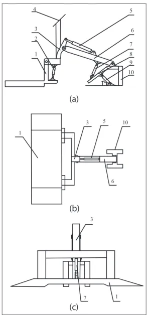
The structure of the newly designed arm-type stereo parking lot is shown in Figure 1. The junction plate and movable arm are joined with the fixed support (compo-nent 10 in Figure 1). The truss arm is then connected to
1 2 3
4 5
6
7
8 9
10
1
3 5
6 10
3
1 7
(a)
(b)
(c)
the movable arm. Finally, the steel tray plate is joined with the truss arm.5–14
To balance the gravity centre of car, two hydraulic cylinders are designed (component 2 in Figure 1) for controlling the steel tray platform. In addition, three hydraulic cylinders are used to connect the different components (components 5, 7 and 9 in Figure 1). Moreover, an additional solar panel is introduced in the arm-type stereo parking lot to make it energy-efficient and environmentally friendly.
Parameters
The design parameters and performance indicators are shown in Table 1. To reduce welding stress and prevent welding deformation, the pressure type and steel struc-ture materials are required in the manufacstruc-ture of the components. Moreover, the welding cast method is used in the special position of the movable arm with high stress to improve the fatigue strength and rigidity of the components. In particular, all the components near the hinge parts should be made of steel to ensure the strength of the welding.
To attain energy efficiency, the sound and light alarm system, the infrared sensing system, the lighting system and its control system are all supported by the solar panel to conserve electric power. Moreover, the in-position locks, power outage locks, running fault suspension system, electrical overload protection device, photoelectric switch, buffering and alerting sys-tems are all considered in the design to guarantee the safety of the parking lot.
Motion analysis of the novel designed
stereo parking lot
Pose matrix
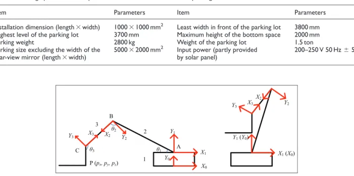
Three virtual coordinate systems are set in the model of the parking lot (Figure 2) to describe the degree of free-dom, establish the pose matrix and finally realize the motion simulation. First, theOX0Y0Z0coordinate
sys-tem is the joining point. Second, theOX1Y1Z1
coordi-nate system is built on the joining point between the fixed support and the movable arm. Third, the OX2Y2Z2 coordinate system is located on the joining
point between the movable arm and the truss arm. Fourth, theOX3Y3Z3coordinate system is on the
join-ing point between the truss arm and the steel tray platform.
As shown in Figure 2, P(px,py,pz) is the coordinate
of the setting point P on the steel tray plate. u1is the included angle between the movable arm AB and the horizontal plane, u2 is the rotation angle between the movable arm AB and the truss arm BC and u3 is the angle between the truss arm BC and the steel tray plate CP.
Forward solutions of kinematic equations of stereo
parking lot
Denavit and Hartenberg proposed a matrix method (D-H method) of establishing possessed coordinates for each joint chain rods to describe the relationship between the translation and rotation of adjacent rods.15 According to the special structure of the proposed
Table 1. Design parameters and performance indicators of the stereo parking lot.
Item Parameters Item Parameters
Installation dimension (length3width) 100031000 mm2 Least width in front of the parking lot 3800 mm Highest level of the parking lot 3700 mm Maximum height of the bottom space 2000 mm
Parking weight 2800 kg Weight of the parking lot 1.5 ton
Parking size excluding the width of the rear-view mirror (length3width)
500032000 mm2 Input power (partly provided by solar panel)
200–250 V 50 Hz65%
P (px, py, pz) X
0 Y0
Y3 X3 X2 Y2
Y1
X1
Y3 X3 X2
Y2
X1(X0) A
Y1(Y0) B
C θ3
θ2
θ1
1 2 3
novel design of the stereo parking lot, we used the D-H method to model the design and then validated the cor-rectness of the established model. In this article, we ver-ified the correctness of the forward kinematics and investigated its inverse kinematics to improve the suc-cess rate of the automatic grasping of objects.15
The 3 degrees of freedom set in the present stereo parking lot are all characterized by having rotational structure, whose characteristic parameters are as shown below:
1. The distance from Yi21 to Yi following the
direction of Xi21 represents the length of the
connecting rod ai; the second and third lengths
of the connecting rod are a2=h and a3=k,
respectively.
2. The angle around Yi21 following the direction
fromYi21to Yiis defined as the torsion angle.
Given that all the connecting rods are in the same plane, all coordinate system origins are in the same plane. Therefore,a1=a2=a3= 0. 3. The distance from Xi21 to Xi following the
direction of Zi is defined as the offset di.
Similarly, the values of the offsetdiare all equal
to 0, that is,d1=d2=d3= 0.
4. The angle around Zi21 following the direction
fromYi21toYiis defined as the coupler-angle.
According to the above coordinate systems, the parameters of 3 degrees of freedom parking device are obtained and shown in Table 2.
According to the parameters shown in Figure 2, the homogeneous transformation matrices of the three con-necting rods were obtained as follows
A1=
cosu1 sinu1 0 0
sinu1 cosu1 0 0
0 0 1 0
0 0 0 1
2 6 6 4 3 7 7 5
ð1Þ
A2=
cosu2 sinu2 0 h
sinu2 cosu2 0 0
0 0 1 0
0 0 0 1
2 6 6 4 3 7 7 5
ð2Þ
A3=
cosu3 sinu3 0 0
sinu3 cosu3 0 k
0 0 1 0
0 0 0 1
2 6 6 4 3 7 7 5
ð3Þ
On the basis of equations (1)–(3), theR transforma-tional matrices were obtained and shown as follows
R=
nx ox ax px
ny oy ay py
nz oz az pz
0 0 0 1
2 6 6 4 3 7 7 5
ð4Þ
T3=A1A2A3=R ð5Þ
where
nx= cos (u1+u2+u3) nx= sin (u1+u2+u3) nz=0
ox= sin (u1+u2+u3) oy= cos (u1+u2+u3) oz=0
ax=0 ay=0 az=0
px=k cos (u1+u2) +hcosu1 py=ksin (u1+u2) +hsinu1
The R transformational matrix describes the posi-tional relation of the steel tray platform relative to the reference coordination system, which is the theoretical foundation of the kinematics simulation analysis of the stereo parking lot.
Inverse solutions of kinematic equations of stereo
parking lot
The inverse solutions of the kinematic equations are the process of looking for the value of the joint vari-ablesu1,u2andu3when the pose of the steel tray plat-form has been pre-set.16To conveniently solve for the equations, two intermediate variables, namely,randu,
were introduced into the equations. The inverse solu-tions are obtained with the use of the following triangle substitute
px=rcosu,py=rsin u ð6Þ
where
r= ffiffiffiffiffiffiffiffiffiffiffiffiffiffiffiffip2 x+p
2 y
q
u= arctanpy
px
(a) The value ofu2
p2x+p2y=k2+2khcos u2+h 2
ð7Þ
Table 2. Denavit–Hartenberg parameters of connecting rods.
Connecting rod numberi ui a di ai Range (°)
1 u1 0 0 0 28–105
2 u2 0 0 h 41–93
Substituting equation (6) in equation (7) gives
u2= arc cos r2
k2
h2
2kh ð8Þ
(b) The value ofu1
The inverse transformation A11 is used as the
pre-multiplication to equation (5). Given thatA1A11=1,
the inverse transformationA1
1 was obtained as follows
A11T3=A2A3=
cos (u2+u3) sin (u2+u3) 0 h+k cosu2
sin (u2+u3) cos (u2+u3) 0 ksinu2
0 0 1 0
0 0 0 1
2 6 6 4 3 7 7 5
ð9Þ
Element (2, 4) at both ends of matrix equation (9) was set with a corresponding equality, and the follow-ing was obtained
pxcosu2+pysinu1=h+k cosu2 px(sinu1) +pycosu1=k sinu2
ð10Þ
Equations (6) and (8) were plugged into equation (9) to gainu1
cos (u1u) = (r
2
k2
h2
)=2h+h r sin (u1u) =k sinbr
u1u= arc tan ksinu2
(r2
k2
h2
)=2h+h
u1= arc tanpy
px + arc tan
ksinu2
(r2 k2
h2
)=2h+h
cos (u2+u3) = cosu1
8 > > > > > < > > > > > :
ð11Þ
(c) The value ofu3 Let
T1
3 R=T
1
3 T3 ð12Þ
Element (1, 4) and Element (2, 4) at both ends of matrix equation (12) were set with a corresponding equality, and the following was obtained
pxcos (u1+u2+u3) +py sin (u1+u2+u3)
hcos (u2+u3)kcosu3=0
px sin (u1+u2+u3) +py cos (u1+u2+u3)
+hsin (u2+u3) +k sinu3=0
8 > > < > > :
ð13Þ
where
cos(u1+u2+u3) = 1
that is
u1+u2+u3= 2np
Therefore, the value of u3 was then obtained as follows
cosu3=pxhcos ( u2+u3)
k sinu3= py
+hsin (u2+u3)
k u3= arc tan
hsin (u2+u3) +py
hcos (u2+u3)px 8
> <
> :
ð14Þ
Various results can be obtained for the inverse solu-tions of the kinematic equasolu-tions of stereo parking lot. However, some of the results cannot be realized because of the limitations in the designed structure of the pres-ent parking lot. For example, the connecting rod can-not move in the entire range of 360°. Thus, an optimal solution should be selected to satisfy the requirements of the working.
Trajectory planning
The purpose of trajectory planning is to design the para-meters of the steel tray platform during the working process, including the displacement, the speed and the accelerated speed, among others, and to find the opti-mal track from the initial state to the target state. The expecting pose can be attained by reasonably control-ling the movements of the connecting rods.17Trajectory planning is generally performed using three methods: three polynomial interpolation, high-order polynomial interpolation and parabola over linear interpolation.
The positional constraint conditions of the move-ment locus function areu(0) =u0,u(tf) =uf,u#(0) = 0 andu#(tf) = 0. The polynomial that satisfies the above constraint conditions are as follows
u(t) =a0+a1t+a2t2+a3t3 ð15Þ
The speed of the connecting rod was obtained as the first-order derivative of equation (15)
u0(t) =a1+2a2t+3a3t2 ð16Þ
The accelerated speeds of the connecting rods were obtained as the derivative of equation (16)
u00(t) =2a2+6a3t ð17Þ
The constraint conditions were introduced into equations (15)–(17), and the values ofa0,a1,a2anda3
were then obtained as follows
a0=u0 a1=0
a2=3(uf u0)=tf2
a3=2(u
f u0)=t 3 f 8 > > < > > :
ð18Þ
Finite element calculation and analysis of
steel tray platform
Deformation of steel tray platform
Currently, steel Q235 is typically chosen as the material for steel tray platforms. Its material properties are shown in Table 3.18
The steel tray platform component is very important for the parking equipment. Thus, ANSYS software is adopted to simulate its motion and load stress states to
optimize the structure of the parking equipment. To ensure that the simulation results are as realistic as pos-sible, the finite element model is only simplified as necessary.
The red arrow area is where the auto tire is in con-tact with the steel tray platform and where the static load is added. The grid of the steel tray platform entity model and the deformation after loading are shown in Figure 4.
Figure 4 shows that the values of deformation of the steel tray platform increase from a fixed position to the outside. On this foundation, the stress distribution of the steel tray platform was further studied.
Load stress of the steel tray platform
The steel tray platform is made of plastic material. The stress analysis on the steel tray platform is subject to the fourth strength theorem of material mechanics.
1
3
2
tf t 0
θt
θf
θ0
Figure 3. Movement track of connecting rods.
u0is the initial position of connecting lot started at timet0, andufis the
target position at timetf. Tracks 1 and 2 are the movement tracks
without a cubic polynomial interpolation trajectory. Track 3 is the movement track after three times of polynomial interpolation trajectory.
Table 3. Parameters of steel tray platform material.
Material Elasticity modulus (MPa)
Density (g/cm3) Poisson’s ratio
Q235 2.063105 7.9 0.3
Figure 4. Static load analysis of the steel tray platform.
Figure 5. First principal stress distribution of the steel tray platform.
Figure 5 shows the first principal stress distribution of steel tray platform.
Equivalent stress distribution of the steel tray plat-form in theY-direction is shown in Figure 6.
From the perspective of the distribution of stress, when the vehicle was parked in the steel tray platform, the first principal stress of the steel tray platform was 0.174573 MPa. Meanwhile, it yielded a higher equiva-lent stress in the Y-direction, that is, 0.154841 MPa. Both measurements are smaller than the tensile strength 380 MPa of Q235. Therefore, the strength of the steel tray platform is sufficiently large to meet the design and operation requirements.
According to the principal stress pattern, the maxi-mum stress occurs in the joint of the car plate and the load table column. However, the stress here can be
improved by thickening the ribbed plate between the column and the steel tray plate.
Motion simulation of stereo parking lot
Motion simulation
The three-dimensional entity model and the motion simulation are conducted using the Pro/E three-dimensional mapping software. The three-three-dimensional entity model of the parking lot is shown in Figure 7 (left section). After the entity model was established, interference inspection was conducted to avoid any interference problems during operation. Finally, the motion track was confirmed to realize the safety and efficiency in Figure 7. Figure 8 shows the installation of the parking equipment in the residential area. Figure 9 shows the double stereo parking equipment. The use
Figure 7. Three-dimensional entity model and motion track of the parking lot. The left section of this figure is the
three-dimensional entity model of the parking lot. The right section is the motion track of the parking lot: (a) the initial situation when the car moved onto the steel tray platform, (b) and (c) the process of moving car to the target location and (d) the final position after parking.
Figure 8. Parking equipment installation in a residential area.
of the device is a times more than the ground parking lot, but it still cannot solve the space utilization of the concave and convex sections above the flower beds and lawns of residential areas and agency units. Thus, a novel arm-type single stereo parking lot can be placed in the concave and convex sections of flower beds and lawns. As a result, such an approach not only meets the requirements of parking but also avoids disturbing normal natural plant growth. When the car is parked in the air, the more that it would not affect the traffic, and it can avoid scratches and window breakage. The device is characterized by having a simple and compact structure, convenient and quick operation, and it is very suitable for residential areas and agency units.
Motion process analysis
To clarify the motion process of the parking lot, the characteristics of the five hydraulic cylinders during the
first 8 s at the start of the parking process are analysed and shown in Figure 10.19 The displacement curve shown in Figure 10(a) supposes that the truss arm hydraulic cylinder and the swing arm hydraulic cylinder move directly. Therefore, their accelerated speeds are 0 in Figure 10(b), and their moving speeds are constant in Figure 10(c). Meanwhile, the displacement of the levelling hydraulic cylinder increases with a positive accelerated speed as shown in Figure 10(b) and increas-ing speed as shown in Figure 10(c). In contrast, the accelerated speed of the steel tray hydraulic cylinder was negative and constant, indicating that the displace-ment declined while the parking lot was rising.
The force curves of the five hydraulic cylinders during the first 8 s of lifting are as shown in Figure 10(d). At the beginning of the parking process, the levelling hydraulic cylinder was stretched. Thus, the force value was posi-tive. However, the other three kinds of hydraulic cylin-ders were compressed. The force they faced was actually
stress, which was expressed as negative in Figure 10(d). During the parking process, the different components faced different stresses. The force of the levelling hydrau-lic cylinder increased along with lifting. This finding proves that the levelling hydraulic cylinder plays the dominant role during the parking process. The force suf-fered by the steel tray platform hydraulic cylinder remained stable and was equal to the weight of the car.
In contrast to the abovementioned hydraulic cylin-ders, the force of the swing arm hydraulic cylinder and the truss arm hydraulic cylinder decreased with time. Therefore, the compression force exerted on them was reduced with lifting.
Conclusion
A novel design of an arm-type stereo parking lot is introduced in this study. The objective of the proposed parking lot is to solve the problem of static traffic prob-lem – parking probprob-lems in large cities. The single park-ing lot is suitable for the family or institutions. First, the safety is considered by in-position lock systems and so on. The energy supply can be saved by introducing solar panels into the design. The bottom space could still be used as lawns, thus promoting environmental friendliness and enjoyment for people. Second, finite element analysis was conducted to explore the state of the load distribution of the steel tray platform. Third, motion analysis was conducted to explore the mechan-ism during the working of the parking lot and to opti-mize the trajectory planning and the motion track. On one hand, the optimal results of tracking planning were obtained on the basis of the forward and inverse solu-tions of the kinematic equasolu-tions of the stereo parking lot. On the other hand, the motion process is simulated by the Pro/E three-dimensional mapping software and is analysed based on the displacement, force, speed and acceleration. The results suggest that the force of levelling hydraulic cylinder increased along with lifting, manifest-ing that durmanifest-ing the parkmanifest-ing process, the levellmanifest-ing hydrau-lic cylinder plays the dominant role. The force suffered by the steel tray platform hydraulic cylinder remains sta-ble, whereas the force of the swing arm hydraulic cylin-der and the truss arm hydraulic cylincylin-der decreases with time. The simulation results prove that the correctness and accuracy of the stereo parking lot under motion mode are feasible in residential area and units.
Declaration of conflicting interests
The author(s) declared no potential conflicts of interest with respect to the research, authorship and/or publication of this article.
Funding
This work was supported by the Fundamental Research Funds for the Central Universities No. 2014XS25.
References
1. Kimms A, Maassen KC and Pottbaecker S. Guiding traffic in the case of big events with spot checks on traffic and additional parking space requirements.Cent Europ J Oper Re2012; 20: 755–773.
2. Yang H, Liu W, Wang XL, et al. On the morning com-mute problem with bottleneck congestion and parking space constraints. Transport Res B: Meth 2013; 58: 106–118.
3. http://wardsauto.com/ar/world_vehicle_population_110815 4. Welding of stainless steels and other joining methods (A
designers’ handbook series N°9002). Nickel Development Institute; American Iron and Steel Institute, http://www. nickelinstitute.org/;/Media/Files/TechnicalLiterature/ WeldingofStainlesssSteelandotherJoiningMethods_900 2_.pdf
5. http://v.youku.com/v_show/id_XMzUwMjE1MzA0.html 6. Fu J, Gao F and Pan Y. Forward kinematics solutions
of a special six-degree-of-freedom parallel manipulator with three limbs. Adv Mech Eng 2015; 7(5). DOI: 10.1177/1687814015582118.
7. Zhu Y, Zhu SS, Wang GJ, et al. Kinematics analysis of 6-DOF transportation vibration platform.Adv Mat Res
2011; 199–200: 1419–1422.
8. Tian DX and Han SK. Actual motion of 3-DOF parallel robot.Adv Mat Res2012; 383–390: 5059–5065.
9. Li JJ and Zhao XH. Kinematics modelling and simula-tion of tracked five DOF mobile manipulator.Adv Mat Res2012; 433–440: 4831–4836.
10. Tao K and Wang X. Kinematical analysis on three-DOF cylindrical industrial manipulator. Adv Mat Res 2012; 415–417: 775–778.
11. Zhao DB, Yi JQ, Zhang WZ, et al. Arms kinematics on a humanoid robot TH-1. Robot 2002; 24: 502–507 (in Chinese).
12. Jin ZL and Li YB.4-DOF parallel mechanical arm. Patent CN200610012824.6, China, 2006 (in Chinese).
13. Jin ZL, Li YB and Wang YL.A 6-DOF hybrid mechani-cal arm. Patent CN200620025075.6, China, 2006 (in Chinese).
14. Ding C, Jiao X, Duan P, et al. Dynamics analysis and simulation for manipulator with five degree of freedom. In:Proceedings of the world congress on intelligent control and automation, Jinan, China, 7–9 July 2010, pp.5576– 5581. New York: IEEE.
15. Cai ZX. Robotics. Beijing, China: Tsinghua University Press, 2009 (in Chinese).
16. Sun L, Ma J and Ruan X. Trajectory planning and simu-lation of 6-DOF manipulator. Control Eng China2010; 17(3): 388–392.
17. Li YB, Jin ZL and Ji SM. Design of a novel 3-DOF hybrid mechanical arm. Sci China Ser E 2009; 52: 3592–3600.
18. Zhao YG, Xiao YF and Chen T. Kinematics analysis for a 4-DOF palletizing robot manipulator. Appl Mech Mater2013; 313–314: 937–940.
19. Tao Y, Chen F and Xiong H. Kinematics and workspace of a 4-DOF hybrid palletizing robot. Adv Mech Eng