Advances in Radio Science, 3, 437–440, 2005 SRef-ID: 1684-9973/ars/2005-3-437
© Copernicus GmbH 2005
Advances in
Radio Science
Addendum to Kleinheubacher Berichte 2003
Field-Theoretical Investigations of the Influence of Mutual Coupling
Effects on the Capacity of MIMO Wireless Links
H. Ndoumb`e Mbonjo Mbonjo, G. Wu, and V. Hansen
Chair of Electromagnetic Theory, University Wuppertal, Rainer-Gruenter-Str. 21, 42119 Wuppertal, Germany
Abstract. We present a MIMO channel model which takes into account mutual coupling effects at the receiver and trans-mitter array in order to assess the influence of mutual cou-pling effects on the capacity of MIMO channels. We eval-uate the mutual impedances using a general approach based on the electric field integral equation (EFIE) and its imple-mentation by the method of moments (MOM). We compute the capacity of a 2×2-MIMO system in a one path scenario for square half wavelength patch antenna elements and half wavelength dipole antenna elements. The capacity of the MIMO system with and without coupling increases com-pared to the single antenna transmission for the patch antenna elements. On the contrary for half wavelength dipole antenna elements we have found that the MIMO system degenerates to a one-transmitting, one-receiving antenna system due to mutual coupling.
1 Introduction
In Multiple Input Multiple Output (MIMO) systems antenna arrays are used at both the receiver (M antenna elements) and transmitter (N antenna elements) side. It was shown in (Telatar, 1999; Foschini and Gans, 1998) that MIMO systems improve potentially the capacity of wireless links and that under certain circumstances the capacity gain of a MIMO system scales with the number of transmitting and receiving antennas. But in these assumptions mutual coupling effects between antenna elements are ignored. However, mutual coupling is an important electromagnetic characteristic of an antenna array and therefore can considerably affect its per-formance. Especially, due to mutual coupling the currents on the antenna elements of an array interact. This effect is char-acterized by the mutual impedance and becomes meaningful for closely spaced antenna elements. Thus it is necessary to
Correspondence to:H. Ndoumb`e Mbonjo Mbonjo ([email protected])
include mutual coupling in the MIMO channel modelling. The influence of mutual coupling on MIMO systems was in-vestigated in (Svantesson, 2001; Chiurtu, 2002) for arrays of dipole antennas starting with approximated analytical ex-pressions for the mutual impedances between dipole anten-nas of finite length available in the common antenna liter-ature (Balanis, 1982). However, other types of antenna el-ements, e.g. patch array antennas, can also be employed in MIMO systems. Thus it is reasonable to develop a general approach for the computation of the mutual impedance.
This paper is organized as follows: In Sect. 2 the mod-elling of mutual coupling effects in MIMO channels is pre-sented. The computation of the mutual impedance is outlined in Sect. 3. Section 4 contains numerical results obtained from our computations. In Sect. 5 the conclusion of this work is presented.
2 Modelling of mutual coupling in MIMO channel
The starting point of our investigation is the voltage trans-fer matrix of a MIMO system as given in (Chiurtu, 2002). The MIMO voltage transfer matrix is obtained from the impedance matrix representation
Us Ur
=
A B C D
Is Ir
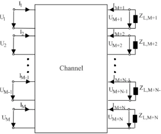
(1) of a M+N-port model of a MIMO system usingM trans-mitting antenna elements andN receiving antenna elements where each antenna is associated with a porti=1..(M+N ). This model is depicted in Fig. 1. The ports associated with the transmitter array are on the left and those related to the receiver array are on the right. In Eq. (1)Ur resp. Ir are the column vectors of voltages resp. currents at the receiver andUs resp. Is denote the column vectors of the applied voltages resp. the input currents at the transmitter array.
438 H. Ndoumb`e Mbonjo Mbonjo et al.: Influence of Mutual Coupling Effects
Fig. 1.Multi-port model of a MIMO system.
correspond to the mutual impedance between antenna elementiand antenna elementj of the transmitter ar-ray.
– Bis aM×NMIMO channel transfer matrix whose ele-mentsBij, i=1..M, j=1..N correspond to the channel transfer impedance between antenna elementi of the transmitter array and antenna elementj of the receiver array.
– Cis aNxMMIMO channel transfer matrix whose ele-mentsCij, i=1..N, j=1..M correspond to the channel transfer impedance between antenna elementi of the receiver array and antenna elementj of the transmitter array and
– Dis aNxNmutual impedance matrix of the receiver ar-ray whose elementsDij, i=1..N, j=1..N represent the mutual impedance between antenna elementiand an-tenna elementj of the receiver array.
It follows from reciprocity thatCis the transpose ofBi.e. C=BT. Assuming that each porti=M+1..(M+N ) of the receiver array is terminated by a load impedance ZL,i the currentsIr and voltagesUr at the receiver array are related through:
Ur = −ZLIr (2)
ZLrepresents the diagonal matrix of the load impedances at the receiver array. Inserting Eq. (2) into Eq. (1) we solve for Ur=f (Us)and obtain
T=(IN+DZ−L1−BTA−1BZ−L1)−1BTA−1 (3) for the voltage transfer matrixTof the MIMO system. In Eq. (3) IN is the (N×N)-identity matrix. Without mutual couplingAandDare diagonal matrices whose entries are the self impedances of the receiving resp. transmitting antenna elements.
3 Computation of mutual impedance
The mutual impedance between two antennas (denoted as an-tenna 1 and anan-tenna 2) is derived from the reaction and reci-procity theorems (Unger, 1967; Balanis, 1982) and is given as
Z12 = −
1
I1I2
Z r22
r21
E12(r2)J2(r2) dr2 (4)
where J2(r2) is the current distribution on antenna 2 and
E12(r2)is the electric field produced by the current
distribu-tionJ1(r1)on antenna 1 along antenna 2. I1andI2are the
input currents of the antennas. Using fundamental electro-magnetic theory (Green’s function concept) (Balanis, 1982) E12(r2)is related toJ1(r1)by
E12(r2)=
Z r12
r11
↔
G
E
J (r1,r2)J1(r1) dr1. (5)
The integrations in Eq. (4) resp. in Eq. (5) are performed over the entire regions of antenna 2 resp. antenna 1. In Eq. (5)↔G
E
J
(r1,r2)is the Green’s function for the electric field. Inserting
Eq. (5) into Eq. (4) we obtain
Z12= −
1 I1I2
Z r22
r21
Z r12
r11
↔
G E
J (r1,r2)J1(r1)J2(r2) dr1dr2 (6)
for the mutual impedance Z12 between antenna 1 and 2.
Equations for the Green’s function↔G
E
J (r1,r2)are available
for several kinds of space (free space (Mittra, 1973), layered media (Hansen, 1988), half space as a special case of lay-ered media). Only in some special cases where the current distribution on the antennas is approximately known (for ex-ample thin wire dipoles in free space) it is possible to give an analytically closed expression for the mutual impedance be-tween the antennas. Therefore the current distribution on the antennas is evaluated numerically with the Method of Mo-ments (MOM) (Harrington, 1968). In the MOM the antenna structure is divided into subregions and the unknown current distributionJ(r)on the antenna is evaluated using a linear combination ofSn basis functionsβ1,..,Sn(r)with unknown amplitudesJˆ1..Sni.e.
J(r)= Sn X
n=1
ˆ
Jnβn(r). (7)
The unknown amplitudes of the current basis functions are solved using the electric field integral equation (EFIE) pro-cedure: Eq. (7) is inserted into an integral representation of the electric field such as Eq. (5) and the electric field is eval-uated atSm test points with simultaneous consideration of the boundary conditions for the electric field. Then the result is weighted with a functionα1..Sm(r). Applying these three steps we obtain the matrix equation
H. Ndoumb`e Mbonjo Mbonjo et al.: Influence of Mutual Coupling Effects 439
Fig. 2. Mutual impedance between two square half wavelength patch antennas as function of their separation.
Each elementZ˜mnof the (SmxSn)-Z˜ matrix represents the in-teraction between basis functionβn, n=1..Snand test func-tionαm, m=1..Smand is given by
˜
Zmn=
Z rm2
rm1
Z rn2
rn1
↔
G E
J (rn,rm)βn(rn)αm(rm) drndrm. (9)
In Eq. (8)Un=(U1, U2, ..., USn)T denotes the voltage vec-tor whose entries are zero except at the antenna feed point. Equation (8) is then solved for the unknown current coeffi-cientsJˆ1..Sn.
From the MOM solution we obtain
J1(r1)=
Sn
X
n=1
ˆ
J1nβn(r1) J2(r2)=
Sm
X
m=1
ˆ
J2mβm(r2) (10)
for antenna 1 resp. antenna 2. We include Eq. (10) in Eq. (6) and obtain
Z12= −
1
I1I2
Sn X
n=1
Sm X
m=1
ˆ
J1nJˆ2mZ˜mn (11)
for the mutual impedance between antenna 1 and antenna 2. For the computation of the Z˜mn we choose the test func-tions according to the Galerkin method (Sadiku, 2001) i.e. αm(r)=βm(r).
Fig. 3.One path scenario: the antennas are in free space.
Figure 2 depicts the obtained values for the mutual impe-danceZ12=R12+j X12between two square half wavelength
patch antennas for different spacings between the antennas. The computation of the patch antennas is based on a spectral domain analysis of an EFIE formulation applying the appro-priate Green’s functions of layered media (Vaupel, 1999).
4 Numerical results
In this section we present and discuss our numerical re-sults. We compute the channel capacity of a MIMO system withM=2 transmitting andN=2 receiving antennas with and without coupling in the one path scenario depicted on Fig. 3. The capacity of aN×M-MIMO system with no channel state information (CSI) at the transmitter i.e. when the chan-nel is unknown to the transmitter is given by the following equation (Telatar, 1999)
C= k X
i=1
log2(1+
λiSN R
M ) bps/Hz (12)
In Eq. (12)λ1,λ2... λk are the nonzero eigenvalues of the matrix
W=TTH for N ≤M
=THT for M≤N
(13)
k=min(M,N) andSN R is the average signal to noise ratio at each receiving antenna. The superscriptH in Eq. (13) de-notes the Hermitian transpose ofT. Equation (12) represents the capacity of a MIMO system as the sum of capacities ofk
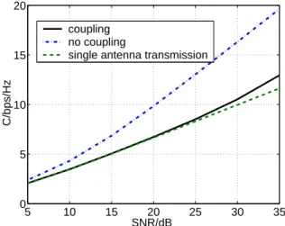
parallel single input single output (SISO) subchannels. The eigenvaluesλ1,λ2...λkof the matrixWare the power gains of the subchannels. Figure 4 shows the obtained capacity values versus the SNR with and without coupling for patch antenna elements (ds=dr=0.6λ,r≈215λ withλ the wave-length). The dashed curve represents the capacity values of a one-transmitting, one-receiving antenna system (N=M=1). We setZL,1=ZL,2=50for the load impedances at the
440 H. Ndoumb`e Mbonjo Mbonjo et al.: Influence of Mutual Coupling Effects
5 10 15 20 25 30 35 2
4 6 8 10 12 14 16 18
SNR/dB
C/bps/Hz
coupling no coupling
single antenna transmission
Fig. 4.Capacity of the MIMO system for patch antenna elements: ds=dr=0.6λ;r≈215λ.
than the capacity of the SISO system. Furthermore there is no significant difference between the capacity of the MIMO system with and without coupling. This is due to the low coupling of the patch antennas.
Figure 5 shows the obtained capacity curve versus SNR with and without coupling for half wavelength dipoles (ds=dr=0.4λ, r≈215λwithλ the wavelength). It follows from Fig. 5 that in this scenario the capacity of the MIMO system without consideration of mutual coupling increases compared to the capacity of a single antenna transmission system: We obtain approximately a 2 dB increase of the ca-pacity for aSN Rvalue of 35 dB. However, with mutual cou-pling the MIMO system degenerates in a one-transmitting, one-receiving antenna system and there is no capacity gain compared to the SISO case.
5 Conclusions
In this paper we have presented a MIMO channel model which considers mutual coupling effects at the receiver and transmitter arrays. We have obtained an expression for the MIMO voltage channel transfer matrix from the impedance matrix representation of the M+N (M is the number of transmitting antennas elements andN is the number of re-ceiving antennas) multi-port model of a MIMO system. We have evaluated the mutual impedances using a general ap-proach based on the electric field integral equation (EFIE) and its implementation by the method of moments (MOM). Further, we have computed the capacity of a 2×2-MIMO system (M=2 transmitting antennas andN=2 receiving an-tennas) from our derived channel model with and without coupling in a one path scenario. We have used square patch antennas and half wavelength dipoles in a side-by-side con-figuration as transmitting and receiving antennas in our com-putations. The capacity of the MIMO system with and with-out coupling increases compared to the single antenna trans-mission for the patch antenna elements. On the contrary for
5 10 15 20 25 30 35 0
5 10 15 20
SNR/dB
C/bps/Hz
coupling no coupling
single antenna transmission
Fig. 5.Capacity of the MIMO system for half wavelength antenna elements:ds=dr=0.4λ;r≈215λ.
half wavelength dipoles antenna elements we have found that the MIMO system degenerates in a transmitting, one-receiving antenna system due to mutual coupling.
The results presented in this paper demonstrate that mutual coupling can have a significant impact on MIMO systems. Therefore mutual coupling between antenna elements should be taken into account in the modelling of MIMO channels.
References
Telatar, I. E.: Capacity of Multi-Antenna Gaussian Channels, Euro-pean Transactions on Communications, vol. 10, no. 6, 585–595, 1999.
Foschini, G. J. and Gans, M.: J. On Limits of Wireless Communica-tions in a Fading Environment When Using Multiple Antennas, Wireless Personal Communications, vol. 6, 311–335, 1998. Svantesson, T. and Ranheim, A.: Mutual Coupling Effects on the
Capacity of Multielement Antenna Systems, IEEE International Conference on Acoustics, Speech, and Signal Processing, Salt Lake City, USA, May 2001.
Chiurtu, N.: Multiple Antenna Systems for Mobile Communi-cations, PhD Thesis, Swiss Federal Institute of Technology (EPFL), Lausanne, Switzerland, December 2002.
Balanis, C.: Antenna Theory: Analysis and Design, John Wiley & Sons, New York 1982.
Unger, H. G.: Elektromagnetische Wellen II, Vieweg & Sohn Ver-lag, Braunschweig 1967.
Mittra, R.: Computer Techniques for Electromagnetics, Pergamon Press, Oxford 1973.
Hansen, V.: Numerical Solution of Antennas in Layered Media, John Wiley & Sons, New York, 1988.
Harrington, R. F.: Field Computation by Moment Methods, Cazen-ovia, New York 1968.
Matthew Sadiku, N. O.: Numerical Techniques in Electromagnet-ics, CRC Press, Boca Raton, 2001.