ABSTRACT
Wear of double crown systems – electroplated
vs. casted female part
Stefan BAYER1, Dominik KRAUS2, Ludger KEILIG3, Lina GÖLZ4, Helmut STARK5, Norbert ENKLING6
1- Dr. Med. Dent., Department of Prosthodontics, Preclinical Education and Dental Materials Science, University of Bonn, Germany; Clinic for Prosthetic Dentistry, University of Bern, Bern, Switzerland.
2- Dr. Med. Dent., Department of Prosthodontics, Preclinical Education and Dental Materials Science, University of Bonn, Germany. 3- Dr. Rer. Nat., Endowed Chair of Oral Technology, University of Bonn, Bonn, Germany.
4- Dr. Med. Dent., Clinic for Orthodontics, University of Bonn, Bonn, Germany.
5- Prof. Dr. Med. Dent. Head of Department of Prosthodontics, Preclinical Education and Dental Materials Science, University of Bonn, Bonn, Germany. 6- Dr. Med. Dent., Clinic for Prosthetic Dentistry, University of Bern, Bern, Switzerland; Department of Prosthodontics, Preclinical Education and Dental Materials Science, University of Bonn, Bonn, Germany.
Corresponding address: Dr. Stefan Bayer - Department of Prosthodontics, Preclinical Education and Dental Materials Science - Welschnonnenstr. 17, 53111 Bonn, Germany - e-mail: [email protected] - Phone: +49-228-28722016 - Fax: +49-228-287-22453
Received: October 29, 2010 - Modiication: August 5, 2011 - Accepted: August 11, 2011
O
bjectives: The wear of telescopic crowns is a common problem often reducing the patient’s satisfaction with the denture and resulting in a renewal of the denture. The study aims to compare the wear behavior of conical crowns using electroplated copings (group e) with standard telescopic crowns with cast female parts (group C). Material and Methods: 10 conical crowns were milled for each group of a cast gold alloy. The specimen of group e had a conicity of 2°. The cast secondary crowns of group C had a 0° design. The electroplated coping was established by direct electroforming. An apparatus accomplishing 10,000 wear cycles performed the wear test. The retentive forces and the correlating distance during insertion and separation were measured. The wear test was separated in a start phase, an initial wear phase and the long term wear period. The retention forcevalue and the force-distance integral of the irst 0.33 mm of each cycle were calculated. Results: The retentive forces were signiicantly higher for group E and the integrals were signiicantly lower for this group except the integral at cycle 10,000. The changes of retention force and integral did not differ signiicantly between both groups in all phases.
The change of the integrals as well as the integral at the particular cycles showed higher interquartile distances for group C. Conclusions: Within the limitations of this study the tested conical crowns showed clinically acceptable retentive properties. The values reached a range comparable to retentive elements tested in recent literature. The values of group
C showed higher ranges. The force measured for group E was signiicantly higher than
for group C but the integrals showed an opposite tendency. The results indicate that an
exclusive analysis of the force is not suficient as the integral is not equivalent to the force
although it describes the retentive property of the system in a better way than the force over a distance is described. Both systems seem to be suitable for clinical practice.
Key words: Dental restoration wear. Denture retention. Dental prosthesis. Implant-supported denture. Overlay denture. Denture precision attachment.
INTRODUCTION
There is a wide choice of different retentive elements that can be used for denture retention1-5,8,13.
Almost all of these systems consist of two main parts used to connect teeth or implants to removable dentures. The male component is ixed
on the tooth or implant and the female component is integrated as part of the removable denture. The systems differ in the particular material combination and the retentive mechanism used for denture retention1-5,12.
has to face. The change is caused by tribological processes affecting the surface structures of the male and female parts6,8,9. The four most relevant
tribological factors are tribochemical reaction, abrasion, adhesion and surface disruption. They can appear separately or can overlap each other10.
The inluence, appearance and combination of these factors are affected by the material and construction of the retentive element.
Concerning the double crown system as retentive element, two main techniques can be considered. At first, the technique using electroplated female parts and at second the technique using cast female components. The systems using electroplated copings as female part gain importance by advantages in clinical practice. This technique is able to connect implants and teeth in a denture compensating systematic misits due to impression and cast model techniques7. So it
is able to achieve a passive it8. As aspects like
cleaning ability, denture retention, extensibility after abutment loss and patient satisfaction also show good results, the interest in this system increases more and more. The technique using cast female parts shows the advantage of a long term experience as the system is well known concerning survival, maintenance and patient satisfaction10,11.
The data concerning the wear behavior of electroplated copings on conical crowns are sparse. Weigl, et al.28 (2000) showed the advantages of
electroplated copings on empress ceramic crowns in denture retention and wear development compared with the combination gold/gold and titanium/titanium16. All three combinations showed
clinically acceptable results but the gold copings on ceramic conical crowns showed less tribological effects and constant retentive forces. Dillschneider, et al.9 (2009) showed that there was almost no
difference in retentive forces when the cone angle was changed from 0° to 2°9. Both studies measured
an overall median retentive force about 4-5 N. The literature concerning the wear of systems using cast female parts is more comprehensive. The studies show clinically acceptable median retentive forces of about 5 N and more sometimes reaching values exceeding 100 N10,17,18.
The study presented here tries to compare systems using electroplated female parts (group e) versus cast ones (group C). The point of interest is to examine whether there are differences in retentive properties and their development or not. From these data conclusions can be drawn concerning the wear behavior.
MATERIAL AND METhODS
The primary crowns for group e were produced with a taper of 2°. The specimens of group C
showed a parallel walled design. Apart from that the primary crowns were manufactured by the same production processes.
gold primary crowns
The primary crowns were modelled in wax (Yeti Fräswachs, Yeti Dental, Engen, Germnay) on a prepared premolar-like metal tooth. The wax model was milled by a wax-milling cutter (Group e with 2°: 496 KR-2°, Meisinger, Neuss, Germany; Group C with 0°: 497 RD-0°, Meisinger, Neuss, Germany). After that the wax was embedded in a casting mould (Deguvest® SR einbettmasse, DeguDent, Hanau, Germany) and cast in high gold alloy (Degunorm, DeguDent). The surface of the crowns was milled with a dental milling device (F3 Milling Device, DeguDent) and a milling cutter (Group E: HM460FR/PR-2°, Meisinger; Group C: HM486 F-0°, Meisinger). The high glossy inish was reached by using pumace and polishing paste (No. 103, Polirapid, Singen, Germany; Pariser Rot, Dentaurum, Ispringen Germany). each of the crowns had an oblong width with an oro-labial distance of 6 mm, mesio-distal distance of 4 mm and a height of 6.5 mm. The thickness reached 0.3 mm. examples of both groups are shown in Figure 1.
group E: Electroplated female parts and cast metal framework
The electroplated copings were produced for group e in combination with the 2° conical primary crowns. The gold crowns had to be illed with
pattern resin to avoid disposal of electroplated gold onto the inner surfaces of the crowns (Pattern Resin, GC, Alsip, USA). The conical crowns were spray-coated using an air-brush with 0.7 bar (Airbrush, C.Hafner, Pforzheim, Germany) to obtain a homogenous thin layer of silver lacquer (Solaris Conducting Silver Varnish, DeguDent) and placed in a fully automated electroplater (Solaris, DeguDent). The gold copings were created by directly electroplating the ceramic surfaces with gold8. electroplating times and currents were
selected to produce layers of approximate 0.25 mm thickness. The Solaris system uses an 8-level graduation for the adjustment of the electroplating process. For the specimens used in this study the electroplating was performed at level 4 as this level should be used for constructions showing a surface of about 115 mm2. The electroplating at level 4
required 5 h. After removing the electroplated coping, the remaining silver layer on their internal surface was completely removed by 53% nitric acid. No retention force adjustment was required for this double-crown system28. An example of the
electroplated copings is shown in Figure 1.
A cast metal framework was necessary for supporting the electroplated female parts. This framework was produced by using a 0.6 mm thermoforming foil (ekolen, erkodent, Pfalzgrafenweiler, Germany) to reach a standardized strength. Before casting, the screw for the axial insertion and separation was placed to be cast in one piece with the framework (Figure 1). In the wear test the screw was used to ix the specimen holder for axial insertion and separation. The modeled structure was then invested in a casting mould and burned out by the manufacturer’s instructions (Optivest®, DeguDent). Non precious
metal (Biosil, DeguDent) was used for casting the framework. Then the framework was thinned out to 0.5 mm thickness. The gold copings were placed onto the conical crown. The female part was inished by gluing the coping and the cast metal framework by a composite cement (AGC® Cem, Wieland Dental, Pforzheim, Germany) (Figure 2).
The alignment of the screws and the connecting of the copings and the cast metal frameworks were performed with the aid of the milling device. This step guaranteed an alignment of the crown’s axis parallel to the direction of insertion and separation.
group C: Cast female parts
The female part was modeled onto the parallel walled primary crown using Pattern Resin® LS (GC,
Tokyo, Japan). The thickness of the resin reached approximately 0.4 -0.5 mm. As the primary crown was still positioned on the milling device the screw needed to move the female part was placed in the appropriate direction of insertion and removal.
The resin female part was embedded and cast using the same materials that were used for the primary crown production. After removal of the specimen out of the casting mould the surface was sandblasted by using aluminum-oxide (Korox®110,
Bego, Bremen, Germany) and sodium-glass (Perlablast® micro 50, Bego) at 2 bar pressure. The
result was controlled by 10 times magniication. Further finishing of the inner surfaces was performed using burnishers of different roughness. The retention force was adjusted at approximately 1 to 3 N by burnishing the inner surfaces of the female part and the outer surfaces of the primary crown. The force was controlled using a measuring instrument (Friktionstester, Krupp, Germany).
wear simulator
The wear simulator is shown in Figure 3. An electric motor produced the force required for
Figure 2- Cross section diagram of a specimen with an electroplated coping: Composite cement (blue) is used for
the ixation of the electroplated coping (yellow) in the cast metal framework (a); The conical crown (green) is ixed
by resin cement (red) onto the specimen holder (b)
Figure 3- Wear apparatus: Digitally controlled electric motor with (1); Light barrier limiting the covered distance
to the insertion and separation path (2); Artiicial saliva
insertion and separation. The positioning accuracy of the carriage driven by this motor was 2 µm. A load cell with a measuring range of ±200 N was used to register the forces with an accuracy of 0.1 N. The control of the wear simulator and recording of the data was performed with DASYLab32 (National Instruments, Munchen, Germany).
wear test procedure
In group e, the electroplated coping was glued into the frame structure during the production process. As this procedure was performed by using the milling device, the longitudinal axis of the female structure was oriented towards the direction of insertion and separation. The female part was screwed onto the specimen holder. The conical crown was placed manually into the coping. After that this crown was glued onto the male part mounting using polymethyl methacrylate (Palavit®
G, Heraeus Kulzer). As the specimen needed no retention force adjustment the wear simulation started and no adjustment cycles were needed28.
In group C, the specimens were ixed at the screw, which was aligned during the production process. The primary crown was ixed to the male part mounting as described for group e.
During the entire wear test, the specimens were moistened with the lubricant at a rate of 5.00 ml/h by a perfusion pump (PeRFUSOR of secura Co. B. Braun type 871602/1, B. Braun, Melsungen, Germany). As lubricant was used a mixture of distilled water and saliva substitute (Glandosane®,
Cell Pharm GmbH, Bad Vilbel, Germany) in a mixing ratio of 1:2.
Retention force measurement:
All specimens were inserted without further retention force adjustment. In accordance with recent literature, each sample was subjected to 10,000 insertion-separation cycles, which corresponded to approximately 10 years of removing and inserting the denture three times
a day4,6. The retention force measurement was
performed after every 20 cycles of axial loading. The female part was joined completely onto the male part with a force of 20 N. The female part was ixed to the linear axis by an electromagnet and then moved. The inserting and separating of the specimen is done three times under permanent recording of retention force and position. The velocity of this movement was set at 2 mm/s.
Data evaluation
For each insertion and separation cycle the maximum retention force value of the irst 0.3 mm separation distance was recorded. Additionally, the force distance integral of the irst 0.3 mm separation was calculated as the value of the separation work.
Statistical analysis
The statistical analysis was performed using Prism 4.0 (Graph Pad Software Inc., La Jolla, CA, USA). The Mann-Whitney test was used for comparison of the median retention force values and the force-distance integrals.
RESULTS
Retention force at cycle 0, 50, 2,000 and 10,000
The initial retention force of the group e specimens reached a median value of 6.54 N and an interquartile range of 2.25 N (Table1, Figure 4). The specimens of group C reached an initial median value of 3.00 N and an interquartile range of 3.14 N. During the wear test the values of group e increased up to 12.79 N at cycle 10,000 with an interquartile distance of 4.45 N. Group C also showed the same behavior of the measured values. At cycle 10,000 the median reached 4.78 N. The statistical comparison of the median values by the Mann-Whitney test showed that the values in group E were signiicantly higher than the values of group
Cycle 0 50 2000 10000
Group E C E C E C E C
Minimum 5.57 1.88 6.05 2.17 8.40 2.08 9.38 2.72
25% Percentile 5.86 2.12 6.20 3.50 9.03 3.69 10.84 3.26
Median 6.54 3.00 7.18 4.54 10.89 4.92 12.79 4.78
75% Percentile 8.10 5.27 9.47 6.49 12.99 5.98 15.29 6.10
Maximum 9.28 8.19 10.94 8.52 13.87 6.65 17.29 6.82
Interquartile distance 2.25 3.14 3.27 2.99 3.95 2.29 4.45 2.83
p-value 0.0196 0.0503 0.0028 0.0028
Table 1- Retention force [N] at 0, 50, 2,000 and 10,000 cycles - descriptive statistics and p values of the comparison of the median values by the Mann-Whitney-test
C at all 4 points in time (Figure 4).
Force distance integral at cycle 0, 50, 2,000 and 10,000
Concerning the initial force-distance integral, group e reached a median value of 0.335 N/mm with an interquartile range of 0.427 N/mm (Table 2, Figure 5). Group C reached a higher median value with 1.070 N/mm and an interquartile range of 0.620 N/mm. This ratio existed up to cycle 10000 with a median of 0.608 N/mm for group e and 0.950 N/mm for group C although the statistical test could only reveal signiicant difference for cycle 0, 50 and 2,000 (Table 2).
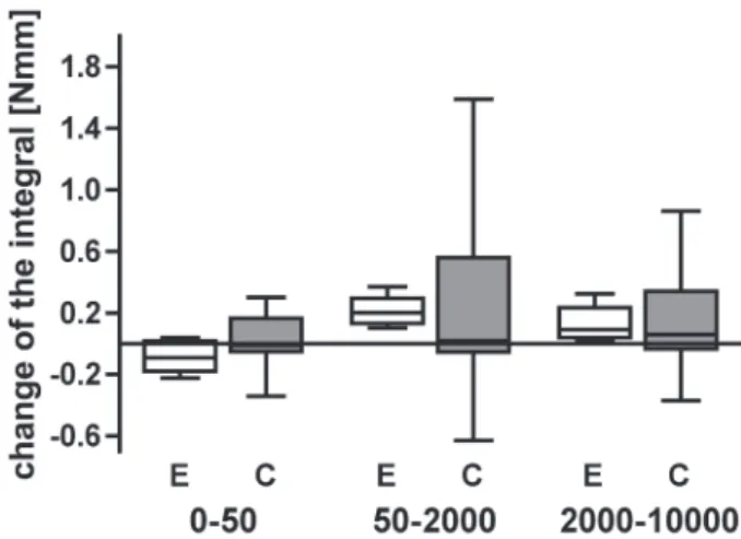
Changes in retention force and force distance integral
If the changes in retention force and the force distance integral are examined, different periods have to be regarded. Figure 6 shows the box-plot diagrams of the measured changes in the retentive
force values and Figure 7 shows the changes of the force-distance integrals. The respective descriptive statistics are shown in Tables 3 and 4.
Group e shows a slight increase in median retentive forces in the starting phase from cycle 0-50 (0.20 N). In this period the retention force change is higher for group C with a median value of 2.13 N, but the difference is not statistically signiicant. During the further cycles of the initial phase (cycle 50-2,000) and the wear phase (cycle 2,000-10,000) the values of group e show an increase in retention force whereas the values of group C decrease slightly. The Mann-Whitney test reveals again that this difference is not signiicant. During these two phases the interquartile difference is higher for group e.
If the change in the retention force integrals is examined and regarded in relation to the absolute values of force it is obvious that the values only change slightly. This behavior was found in both groups. The values of both groups do not show
Figure 4- Retention force values measured at the 4 particular points in time (cycle 0; 50; 2,000; 10,000) for group E (electroplated female part) and group C (cast female part)
Figure 5- Force distance integrals calculated at the 4 particular points in time (cycle 0; 50; 2,000; 10,000) for group E (electroplated female part) and group C (cast female part)
Cycle 0 50 2000 10000
Group E C E C E C E C
Minimum 0.213 0.110 0.206 0.170 0.308 0.320 0.451 0.450
25% Percentile 0.228 0.735 0.224 0.765 0.396 0.845 0.481 0.775
Median 0.335 1.070 0.263 1.050 0.549 0.990 0.608 0.950
75% Percentile 0.655 1.355 0.429 1.340 0.675 1.315 0.883 1.275
Maximum 0.800 1.800 0.575 1.890 0.736 1.420 1.061 1.320
Interquartile distance 0.427 0.620 0.205 0.575 0.277 0.470 0.402 0.500
p-value 0.0290 0.0336 0.0196 0.1986
Table 2- Force distance integral [N/mm] at cycle 0, 50, 2,000 and 10,000 - descriptive statistics and p values of the comparison of the median values by the Mann-Whitney-test
Figure 6- Comparison of the retention force changes of the two groups (E=electroplated female part, C=cast female part). The three phases are shown: start phase (cycle 0-50), initial phase (cycle 50-2,000), wear period (cycle 2,000-10,000)
Figure 7- Comparison of the changes of the force-distance integral of the two groups (E=electroplated female part, C=cast female part). The three phases are shown: start phase (cycle 0-50), initial phase (cycle 50-2,000), wear period (cycle 2,000-10,000)
Phase 0-50 50-2000 2000-10000
Group E C E C E C
Minimum -0.225 -0.340 0.102 -0.630 0.026 -0.370
25% Percentile -0.178 -0.050 0.131 -0.055 0.039 -0.035
Median -0.092 -0.010 0.201 0.020 0.091 0.060
75% Percentile 0.016 0.165 0.295 0.560 0.234 0.340
Maximum 0.040 0.300 0.371 1.590 0.325 0.860
Interquartile range 0.194 0.215 0.164 0.615 0.195 0.375
p-value 0.2977 0.3636 0.6993
Table 4- Descriptive statistics of the force-distance integral changes of the two groups from cycle 0-50, cycle 50-2,000 and 2,000-10000 in N/mm. Negative values stand for a decrease in retention force, positive values for an increase. The p-value for the Mann-Whitney test of the two groups is given
E=electroplated female part, C=cast female part
Phase 0-50 50-2000 2000-10000
Group E C E C E C
Minimum -1.27 -2.57 -2.44 -2.34 -4.83 -0.53
25% Percentile -0.68 -0.41 -1.70 -0.74 -2.32 -0.38
Median 0.20 2.13 2.05 -0.22 1.80 -0.16
75% Percentile 2.39 2.47 5.96 0.61 3.56 0.46
Maximum 4.01 4.28 6.06 1.08 3.71 0.80
Interquartile range 3.07 2.88 7.66 1.35 5.88 0.84
p-value 0.7972 0.5185 0.3677
Table 3- Descriptive statistics of the retention force changes of the two groups from cycle 0-50, cycle 50-2,000 and 2,000-10,000 in N. Negative values stand for a decrease in retention force, positive values for an increase. The p-value for the Mann-Whitney test of the two groups is given
statistically signiicant difference when compared with each other.
DISCUSSION
Referring to the results of this study, it can be stated that the system of electroplated copings on conical crowns and the technique of using cast female parts on parallel walled primary crowns reach suficient and reproducible retentive forces (Figure 4). The electroplated (group e) and the cast (group C) female parts both showed retentive forces comparable to the results of other attachments for removable dentures2,6,29. Both systems showed
a comparable behavior in the change of the retentive properties over the 10,000 wear cycles. This concordance was found with the retention force changes as well as with the change of the force distance integrals (Figure 6, Figure 7). The difference between both systems is the level of the values found in this study (Figure 4, Figure 5). The initial median retention force is twice as high for the electroplated specimens (group e: 6.45 N, group C: 3.00 N). This difference was statistically signiicant. As the specimens of group B were adjusted at the Level of 1 to 3 N retention force, this cannot be assessed as disadvantage of the cast system. On the contrary, achievement of this level shows the good potential of retention force adjustment for the cast system. Whether the system could also be adjusted and tested at a retention force twice as high should be examined in further studies. Concerning the obviously higher range of the force distance integral found for the system using cast female parts, there are two main aspects that could influence the values. The cast system needs adjustment of the retention force of each specimen. This manually performed adjustment results in a higher variability of the surfaces28. In combination with the telescopic
retentive operating mode, the contact between the surfaces persists during the separation of the two parts of the system. This could explain why group C shows a wider range of the values of the integral. The retentive properties of the electroplated system are determined by the precise it of the female part onto the primary crown and the hydrodynamic effect of the saliva lowing into the space widened by the separation of the two parts of the system9,28. As no
manually retention force adjustment is performed the surface is not as variable as assumed for the cast specimens28.
In general, every in vitro wear test setup has to
face the limitations due to the enormous amount of different aspects affecting the in vivo wear
processes14,15,18,19,21,25,28. The simulation is used to
examine two different material combinations under defined conditions regarding one considerable aspect, in this study the wear stability. As a problem
concerning the comparability of the results with other studies there is no adequate ISO standard test set-up for the analysis of the attachment wear processes.
The saliva substitute, the speed of insertion and the separation have to be discussed. A mixture of Glandosane and distilled water was chosen as saliva substitute. This mixture was used in different studies because of its lubricating properties. Other studies used pure Glandosane or silicon oils and thus reach higher retentive forces as the viscosity is higher. Whether the wear is affected by this fact or not has not yet been examined. As both groups are examined under the same conditions the results should be comparable. Concerning the speed of denture removal it has to be stated that there are only few data from clinical trials24. The more
important question is the speed of the jaws during the chewing process, as the denture should stay in place during this movement23. There is a connection
between the speed of the denture’s removal and the retentive force due to the hydraulic system of the electroplated conical crown24. As Rössler found, the
opening speed of the mouth during food chewing is about 760-2650 mm/min23. He also demonstrated
that the retentive force is not further increased by a removal speed exceeding 30 mm/min. There is no need to accelerate the test speed any further19. The
speed of 120 mm/min was a compromise for the test performed in the present study, as it also allows performing the test in an acceptable span of time.
For the simulation were performed 10,000 cycles of insertion and removal. Other studies using many more cycles showed that the relevant retention force change is shown in this period. Usually an almost constant force level is reached after 5,000 cycles3,6,26,27. So the study was constrained to the
relevant space of time simulating a wear period of about 5 years (5,000 cycles) plus a safety margin up to the 10,000th cycle.
For the analysis of the measured retentive forces and force-distance integrals separate spans of time had to be deined, as the retentive force of a retentive element does not develop in a linear modus1,3,25. As
the irst few cycles often dramatically change the retentive properties of a retentive element, is shown the period of cycle 0-50. This is the period in which the restoration is inserted and removed in the dental laboratory during the fabrication of the denture and during the intraoral integration of the denture6,25.
After this the denture is inserted at the patient and an initial wear period starts which normally occurs in the irst 2,000 cycles3,26. After this period the most
retentive elements do not change any further the retention force in wear tests3,33.
This retention should be suficient, as the forces of group C reach and those of group e exceed the values measured for standard clinically used cast gold telescopic crowns11,27. As the force is not higher
than for other attachments there should be no risk of negative inluences due to the level of retention force1,3,6.Compared with other retentive elements,
the two systems tested in this study allow a good reproducibility of retentive forces as they show a small interquartile range of the measured values. Other attachments show a much wider range of retention force resulting in a less predictable result11,22,25. The retention force development does
not differ signiicantly between the two groups. Whether the smaller range of the integral for the electroplated female parts is clinically relevant or not can only be clariied by a clinical study.
CONCLUSIONS
Within the limitations of this study it can be stated that the two double crown systems tested reach suficient retention forces. The electroplated system showed a higher level of retention force. The lower values of the cast specimens are caused by the retention force adjustment aiming at a force of 1-3 N. Concerning the development of the retentive properties, the comparison revealed no statistically signiicant differences between the two groups. Both systems seem to be suitable in clinical practice.
ACKNOwLEDgEMENTS
The study was supported by DeguDent® (Hanau,
Germany).
REFERENCES
1- Bayer S, Gruner M, Keilig L, Hültenschmidt R, Nicolay C, Bourauel
C, et al. Investigation of the wear of prefabricated attachments - an in vitro study of retention forces and itting tolerances.
Quintessence Int. 2007;38:e229-37.
2- Bayer S, Stark H, Mues S, Keilig L, Schrader A, Enkling N.
Retention force measurement of telescopic crowns. Clin Oral Investig. 2010;14:607-11.
3- Bayer S, Steinheuser D, Grüner M, Keilig L, Enkling N, Stark H, et
al. Comparative study of four retentive anchor systems for implant supported overdentures - retention force changes. Gerodontology. 2009;26:268-72.
4- Besimo Ce, Guarneri A. In vitro retention force changes of prefabricated attachments for overdentures. J Oral Rehabil. 2003;30:671-8.
5- Bezzon OL, Goncalves M, Pagnano VO. T-bar clasp-retained removable partial denture as an alternative to implant-based prosthetic treatment. Braz Dent J. 2008;19:257-62.
6- Botega DM, Mesquita MF, Henriques GE, Vaz LG. Retention force
and fatigue strength of overdenture attachment systems. J Oral Rehabil. 2004;31:884-9.
7- Castilho AA, Kojima AN, Pereira SM, Vasconcellos DK, Itinoche MK, Faria R, et al. In vitro evaluation of the precision of working casts for implant-supported restoration with multiple abutments. J Appl Oral Sci. 2007;15:241-6.
8- Diedrichs G, Rosenhain P. Galvano-outer telescope by direct technique. Quintessenz. 1991;42:49-56.
9- Dillschneider T, Nothdurft FP, Abed-Rabbo M, Mitov G, Pospiech PR. In vitro-investigations on the wear behavior of different double crown systems. Dent Mater. 2009;25:e20.
10- Eitner S, Schlegel A, Emeka N, Holst S, Will J, Hamel J.
Comparing bar and double-crown attachments in implant-retained prosthetic reconstruction: a follow-up investigation. Clin Oral Implants Res. 2008;19:530-7.
11- Gamborena JI, Hazelton LR, NaBadalung D, Brudvik J. Retention
of eRA direct overdenture attachments before and after fatigue loading. Int J Prosthodont. 1997;10:123-30.
12- Gonçalves A. Precision removable prosthesis. Rev Bras Odontol. 1952;10:201-11.
13- Gonçalves F, Dias eP, Cestary TM, Taga R, Zanetti RV, Zanetti A, et al. Clinical and histopathological analysis of intramucosal zirconia inserts used for improving maxillary denture retention. Braz Dent J. 2009;20:149-55.
14- Greco GD, Jansen WC, Landre Junior J, Seraidarian PI. Biomechanical analysis of the stresses generated by different disocclusion patterns in an implant-supported mandibular complete denture. J Appl Oral Sci. 2009;17:515-20.
15- Greco GD, Jansen WC, Landre Junior J, Seraidarian PI. Stress analysis on the free-end distal extension of an implant-supported mandibular complete denture. Braz Oral Res. 2009;23:182-9.
16- Greven B, Luepke M, Von Dorsche SH. Telescoping implant
prostheses with intraoral luted galvano mesostructures to improve
passive it. J Prosthet Dent. 2007;98:239-44.
17- Heckmann SM, Schrott A, Graef F, Wichmann MG, Weber HP.
Mandibular two-implant telescopic overdentures. Clin Oral Implants Res. 2004;15:560-9.
18- Heintze SD, Forjanic M. Surface roughness of different dental
materials before and after simulated toothbrushing in vitro. Oper Dent. 2005;30:617-26.
19- Jesus Tavarez RR, Bonachela WC, Xible AA. effect of cyclic load
on vertical misit of prefabricated and cast implant single abutment.
J Appl Oral Sci. 2010;19:16-21.
20- Naert I, Alsaadi G, Van Steenberghe D, Quirynen M. A 10-year
randomized clinical trial on the inluence of splinted and unsplinted
oral implants retaining mandibular overdentures: peri-implant outcome. Int J Oral Maxillofac Implants. 2004;19:695-702. 21- Pereira-Cenci T, Pereira LJ, Cenci MS, Bonachela WC, Del Bel Cury AA. Maximal bite force and its association with temporomandibular disorders. Braz Dent J. 2007;18:65-8. 22- Petropoulos VC, Smith W. Maximum dislodging forces of implant overdenture stud attachments. Int J Oral Maxillofac Implants. 2002;17:526-35.
23- Rodrigues RC, Faria AC, Orsi IA, Mattos MG, Macedo AP, Ribeiro RF. Comparative study of two commercially pure titanium casting methods. J Appl Oral Sci. 2010;18:487-92.
24- Rodrigues RC, Macedo AP, Torres eM, Mattos MG, Ribeiro RF. Retention force of T-bar clasps for titanium and cobalt-chromium removable partial dentures. Braz Dent J. 2008;19:209-13.
25- Rutkunas V, Mizutani H, Takahashi H. Inluence of attachment
wear on retention of mandibular overdenture. J Oral Rehabil. 2007;34:41-51.
26- Setz I, Lee SH, Engel E. Retention of prefabricated attachments
for implant stabilized overdentures in the edentulous mandible: an in vitro study. J Prosthet Dent. 1998:80:323-9.
27- Stancić I, Jelenković A. Retention of telescopic denture
in elderly patients with maximum partially edentulous arch. Gerodontology. 2008;25:162-7.
28- Weigl P, Hahn L, Lauer H-C. Advanced biomaterials used for a
new telescopic retainer for removable dentures. J Biomed Mater Res. 2000;53:320-36.


![Table 1- Retention force [N] at 0, 50, 2,000 and 10,000 cycles - descriptive statistics and p values of the comparison of the median values by the Mann-Whitney-test](https://thumb-eu.123doks.com/thumbv2/123dok_br/14982379.511131/4.892.109.792.934.1143/table-retention-cycles-descriptive-statistics-values-comparison-whitney.webp)