UNCORRECTED PROOF
temperature of laterally unrestrained steel I beams
L.M.R. Mesquita
a, P.A.G. Piloto
a,∗, M.A.P. Vaz
b,
P.M.M. Vila Real
caApplied Mechanics Department, Polytechnic Institute of Bragança, Ap. 1134, 5301-857 Bragança, Portugal bMechanical Department, Faculty of Engineering of University of Porto, Rua Dr. Roberto Frias,
4200-465 Porto, Portugal
cCivil Department, University of Aveiro, Campus Santiago, 3810-193 Aveiro, Portugal
Received 20 September 2004; accepted 29 April 2005
Abstract
1
Lateral unrestrained steel beams when subjected to high temperatures may collapse in service by 2
lateral torsional buckling. This instability state may be predicted in the resistance, temperature and 3
time domain. In this work the beam strength is determined in the temperature domain from a batch 4
of numerical and experimental tests, with a specified degree of utilisation and a typical accident 5
temperature rise. 6
The experimental set-up is a reaction portal frame especially designed for beam elements under 7
elevated temperatures. The specimens were heated by means of electroceramic resistances and a fibre 8
mat specimen cover is used to increase the thermal efficiency. The material and the beam initial state 9
conditions were considered, the experimental procedure being based on constant mechanical action 10
under increasing thermal load. 11
The experimental data was compared with numerical solutions, obtained from a geometric 12
and material nonlinear analysis. A shell finite element modelling, with incremental and iterative 13
procedures, was used in the numerical calculations. Good agreement was obtained between 14
experimental and numerical data. However, both numerical and experimental results lead to higher 15
critical temperatures when compared with the simplified calculation procedure presented in Eurocode 16
for this case. 17
© 2005 Elsevier Ltd. All rights reserved. 18
∗Corresponding author. Tel.: +351 273303157; fax: +351 273313051.
E-mail address:[email protected] (P.A.G. Piloto).
UNCORRECTED PROOF
Keywords: Steel beams; Fire resistance; Lateral buckling; Critical temperature; Experimental tests; Numerical analysis1. Introduction 1
Steel structures are widely used for building construction due to their mechanical 2
properties. Due to the elevated costs in steel fire protection, several research studies have 3
been carried out to predict the structural behaviour of steel members at high temperatures. 4
Bailey et al. [1] performed several numerical calculations on lateral torsional buckling of 5
steel beams for different degrees of utilisation. These authors used a uniform temperature 6
distribution over the length and cross section and found that Eurocode 3, Part 1.2 7
overestimates the critical temperature in fire resistance calculations. Yin and Wang [2], 8
using ABAQUS, presented the results of a parametric numerical study used to investigate 9
the design factors in the lateral torsional buckling resistance and suggested a slenderness 10
modification for steel beams with non-uniform temperature distribution. 11
Full scale experimental measurements made to assess the parameters which influence 12
the behaviour of beams at elevated temperatures are hardly feasible due to the high 13
costs and size limitations of horizontal furnaces. Vila Real et al. [3] conducted a set of 14
experimental and numerical tests, performed in the resistance domain, on European series 15
IPE100 beams subjected to high temperatures. The results obtained with temperatures 16
varying from room conditions up to 600 ◦C lead to a new design formula for lateral
17
torsional buckling that was adopted in the current version of part 1.2 of Eurocode 3 [4]. 18
More recently, Vila Real et al. [5] presented new formulae, based on numerical simulations, 19
which reduce the overconservative approach of part 1.2 of Eurocode 3 to the case of non- 20
uniform bending load conditions. 21
Mechanical properties of steel deteriorate during fire and for conventional steel the 22
yield strength at 700◦C is less than 23% of the specified value at room temperature. To
23
improve the fire resistance of metallic structures, new steel alloys are being developed, 24
the first ones in Japan, and present twice the tensile strength at 600 ◦C of conventional
25
steel [6]. Therefore, conventional steels normally require fire protection to be applied. 26
Thus, one important parameter to be determined is the critical temperature of each beam. 27
This temperature is defined for the collapse condition and is a function of the degree of 28
utilisation. In the present work, this parameter is assessed for a set of unrestrained beam 29
elements, with a constant mid-span concentrated load, while temperature is constantly 30
increased up to collapse; seeFig. 1. 31
2. Design limit state for laterally unrestrained beams 32
Steel I beams subjected to flexural loads have greater stiffness in the web plane than in 33
the lateral plane. Unless these structural elements are properly braced they may collapse 34
by lateral torsional buckling before their full in-plane capacity is attained. Lateral torsional 35
buckling is a structural limit state where large displacements are combined with axial 36
UNCORRECTED PROOF
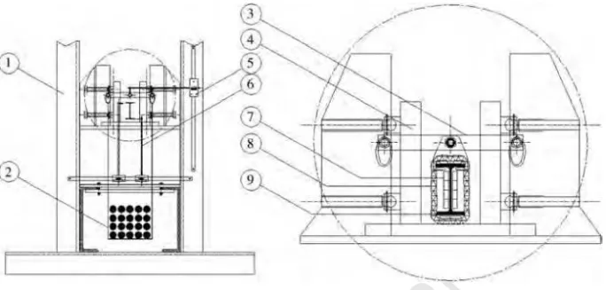
Fig. 1. Physical model under testing.
Table 1
Applied load (degree of utilisation) and critical temperature design values
Beam effective length (m)
q(N/m) Q(N) Ef i,d=
Q L
4 +
q L2
8
EC3-1.2 [4] Vila Real et al. [5]
λL T,θ ,com µ0= Ef i,d
Rf i,d,0 θa,cr ( ◦C) µ
0= Ef i,d
Rf i,d,0 θa,cr( ◦C)
(%) [%]
1.5 134.38 6086.12 2320.09 1.28 56 565.15 50 583.56
2.0 123.00 4315.52 2219.26 1.44 63 546.31 56 565.01
2.5 116.18 3043.06 1992.68 1.56 64 543.64 57 562.36
3.5 118.14 1521.53 1512.24 1.78 59 556.85 53 575.37
4.5 111.64 772.54 1151.69 1.97 53 575.48 47 593.86
InFig. 1 we schematically present the physical model used to produce a combined
1
parabolic and triangular moment distribution, the latter being the most effective. The
2
distributed load accounts for the self-weight of the beam and all the necessary equipment
3
used for the heating process. The full scale tests were prepared to simulate in these loading
4
conditions a degree of utilisation between 53% and 64% [4], as represented inTable 1.
5
As was explained previously, Eurocode 3, part 1.2 [4] presents overconservative results
6
regarding the determination of the design buckling resistance, referred to asMb,f i,t,Rd. The
7
influence of the bending moment distribution on the lateral torsional buckling resistance
8
appears, indirectly, through the value of the critical elastic moment. This parameter is
9
obtained from the energy equation, as can be seen in Eq. (1):
10
MQ
Mcr,M
+ Mq
Mcr,M
=1.423 1+
0.577PyyQ
Mcr 2
−1.003PyyQ
Mcr2,MMq 11
+ 0.577PyyQ
Mcr,M
−0.167 Mq
Mcr,M
(1)
UNCORRECTED PROOF
Fig. 2. Experimental set-up (load and displacement control).
where MQ and Mq represent, respectively, the maximum bending moments due to the 1
concentrated and distributed load, Mcr,M equals the value of the uniform elastic critical 2
moment,Py =π2E Iy/L2andyQ is the vertical position of the concentrated load. 3
According to the new proposal of Vila Real et al. [5], the design buckling resistance 4
should account for a modified reduction factor χL T,f i,mod that takes into consideration 5
the moment distribution over the beam length. This feature is responsible for the last two 6
columns ofTable 1, and increases the beam critical temperature by 20◦C, approximately.
7
Except when considering deformation criteria or when stability phenomena have to be 8
taken into account, for a given steel component the critical temperatureθa,cr at timet for 9
a uniform temperature distribution may be determined, for any degree of utilisationµ0at 10
timet=0, using Eq. (2) [4]: 11
θa,cr =39.19 ln
1
0.9674µ30.833−1
+482. (2)
12
For the lateral torsional buckling collapse mode, the critical temperature calculation 13
requires an iterative procedure. The first step considers Mb,f i,0,Rd at 20 ◦C, with the 14
material reduction factors equal to unity, and then the critical temperature is calculated 15
according to Eq. (2). The degree of utilisation needs to be updated during the following 16
steps until convergence is attained. 17
3. Experimental model 18
A set of fifteen experimental full scale tests has been carried out using beams of the 19
European series IPE 100 [7]. Beams with lengths varying from 1.5 to 4.5 m were tested 20
using three tests for each beam length. The beams were heated by means of electroceramic 21
mat elements, connected to a power unit of 70 kV A. The thermal efficiency of the set-up 22
UNCORRECTED PROOF
Fig. 3. Variation of vertical displacement with temperature.
As shown in Fig. 1, fork supports have been used in the rig to simulate a simple
1
supported beam. In this figure, q represents the beam self-weight and the additional
2
distributed load due to the insulation mat and electroceramic resistances, Q being the
3
applied dead load. To reduce the friction at supports, the distance Lsup−Lexp equal to
4
0.2 m was left without protection.
5
The experimental set-up is represented inFig. 2. The reaction frame (1), with two fork
6
supports (4) was used to fix and load the beams (9). A balance system, represented by (3),
7
was used to apply a dead load at a distanceyQ = −0.105 m from the shear centre. The
8
loading support (2) was designed to maintain the vertical position throughout. Each beam
9
was heated by means of an electroceramic resistance (7), protected by an insulation mat
10
(8). Displacements were followed by three digital measuring rules (5, 6) used for lateral
11
and vertical mid-span measurements.
12
3.1. Experimental procedure 13
Every tested beam was dimensionally controlled with the laser beam method to measure
14
the initial out-of-straightness [7]. The measured values presented a maximum amplitude
15
equal toL/4000, which is considered a small value when compared to the reference value
16
L/1000. This last value was used in the numerical simulations.
UNCORRECTED PROOF
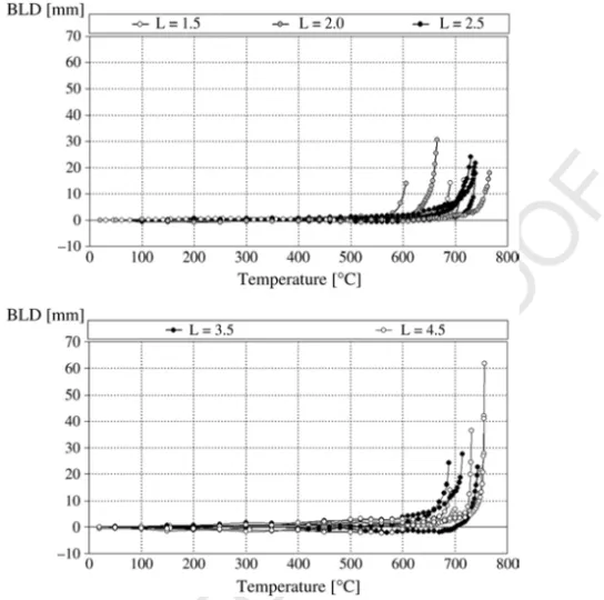
Fig. 4. Variation of bottom lateral displacement with temperature.
To obtain the steel mechanical properties a set of 11 tensile specimens were extracted 1
from the web of the beams and tested according to national standard NP EN 10002-1 [8]. 2
The yield strength fy = Re H =293.2 MPa and the elastic modulusE =210 GPa have 3
been determined from the data average values and compared with the inspection certificate 4
for the profiles. 5
The beams were loaded for a specific degree of utilisation,µ0, approaching real fire 6
conditions. The mechanical load was specified according to typical values used. The degree 7
of utilisation is the ratio between the design load effect and the beam resistance in fire 8
conditions for time equal to zero, as represented according to Eq. (3). This coefficient 9
is a function of the load type which, in this case, is predominantly a triangular moment 10
distribution: 11
µ0=
Ef i,d
Rf i,d,0
= MQ+Mq
Mb,f i,0,Rd
. (3)
12
The beam resistance should be calculated for the expected collapse mode (lateral 13
torsional buckling). Table 1 presents the mechanical load applied on each beam, the 14
slenderness values and the resultant critical temperature calculated by an iterative 15
UNCORRECTED PROOF
Fig. 5. Variation of top lateral displacement with temperature.
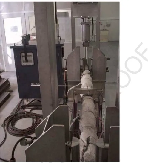
In each test, after the beam had been loaded the temperature was increased at a constant
1
rate of 800◦C/h controlled by a set of thermocouples, typek, laced along the beam length.
2
These thermocouples are used to provide the same heating rate for all electroceramic
3
resistances, assuring a uniform temperature distribution on the exposed beam length; see
4
Fig. 1.
5
For each beam, the vertical (VD) and lateral displacement (top (TLD) and bottom
6
flange (BLD)) have been measured. The experimental data was used to obtain the
7
temperature–displacement curves, represented inFigs. 3–5, for all tested beams.
8
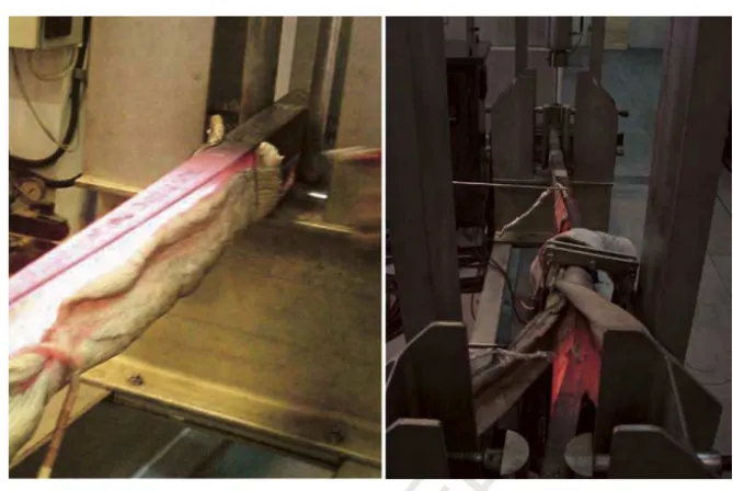
All the tests were performed until a run-away deflection was achieved, the maximum
9
mid-span displacement being shown inTable 2. Typical values used to determine the final
10
stage of each test are based on the displacement or displacement rate for the vertical
mid-11
span displacement. Those reference values areL/20 or a displacement rate ofL2/9000d,
12
for vertical displacements higher than L/30, d being the distance from the top of the
13
structural section to the bottom of the design tension zone [1]. Due to the width of the
14
portal reaction frame used, the maximum vertical displacement measured is less than the
15
reference values. Nevertheless,Figs. 6and7show the on-going test and the ultimate state
16
of one of the beams.
17
The critical temperature has been considered for the last measuring point, for which a
18
small temperature increment produces a large lateral displacement. InFig. 8, all measured
UNCORRECTED PROOF
Table 2
Experimental critical temperature values
Buckling length (m)
Test run number
Critical temperature (◦C)
Average critical temperature/SD (◦C)
Maximum displacement (DV) ratio at mid-span
L1.5-1 717 L/45
1.5 L1.5-2 690 704/13.5 L/63
L1.5-3 705 L/137
L2.0-1 770 L/125
2.0 L2.0-2 606 680/83.1 L/121
L2.0-3 665 L/56
L2.5-1 732 L/71
2.5 L2.5-2 740 737/4.6 L/73
L2.5-3 740 L/63
L3.5-1 744 L/69
3.5 L3.5-2 693 717/25.6 L/135
L3.5-3 715 L/109
L4.5-1 732 L/70
4.5 L4.5-2 757 748/14.2 L/65
L4.5-3 756 L/96
critical temperatures have been registered, the experimental results being slightly greater 1
than those obtained with the simple calculation formula [4]. This can be related to the 2
small thermal insulation near supports, caused by the difference between LsupandLexp, 3
introducing additional stiffness. Another possible cause may be related to the development 4
of friction forces at the supports, producing extra axial restraints that, via the development 5
of catenary action, reduce the beam deflection. This effect may delay the collapse, as was 6
demonstrated by Yin and Wang [9]. 7
4. Numerical model 8
The numerical analysis was based on a geometric and material non-linear programme, 9
ANSYS [10]. Steel beams have been modelled by suitable shell finite elements normally 10
used to model flat or warped, thin to moderately thick shell structures. This element (shell 11
181) has six degrees of freedom at each node, translations in the nodalx,yandzdirections 12
and rotations about the same axes. The deformation shape functions are linear in both 13
in-plane directions and present two integration points for in-plane and five for normal 14
directions. A high rigid beam finite element was used to simulate exactly the application 15
point of the load. 16
The beam cross section was modelled with mid-plane dimensions and the stress/strain 17
relations are based on the Eurocode 3 elastic–elliptic–plastic model; see Fig. 9. The 18
UNCORRECTED PROOF
Fig. 6. Experimental on-going test run.
calculations the elastic modulus and the thermal elongation vary with temperature also, in
1
agreement with Eurocode 3, the other mechanical properties being considered constants.
2
Every structural element presents initial imperfections due to fabrication processes,
3
transportation, storage and construction methods. The initial out-of-straightness
4
imperfection causes a secondary bending moment as soon as any compression load is
5
applied, which in turn leads to further bending deflection and a growth in the amplitude
6
of this bending moment lever arm. Stable deflected shape equilibrium can be established
7
until the internal compression force no longer exceeds the internal moment resistance.
8
The numerical model was implemented with an initial out-of-straightness represented by a
9
harmonic function withL/1000 as the maximum amplitude.
10
Residual stresses were also considered, on the basis of a theoretical distribution
(bi-11
triangular shape), with a maximum value of 30% of the material yield stress. Numerically,
12
these initial residual stresses were introduced at the element integration points, as
13
represented inFig. 10. However, as explained in [11], the beam buckling resistance is less
14
sensitive to the residual stresses when subjected to high temperatures.
15
The numerical model has been implemented with four finite shell elements in the web
16
and the same number over the beam flanges. The beam ends were modelled by two
17
fork supports, constraining vertical and lateral displacements and letting the beam warp
18
freely. An iterative procedure was implemented using material and geometric non-linear
UNCORRECTED PROOF
Fig. 7. Final stage of experimental test run.
Fig. 8. Critical temperature results for all beams tested.
behaviour and temperature increments at a specific rate of 800◦C/h. To simulate the beam
1
heating an autostepping method, based on the temperature field imposed over each node, 2
was used. In the numerical simulation a temperature distribution uniform over the whole 3
beam was considered. 4
The critical temperature was defined as the last temperature at which the equilibrium 5
UNCORRECTED PROOF
Fig. 9. Conventional steel stress–strain curve at elevated temperatures.
Fig. 10. Residual stress model applied to shell elements.
inFig. 8, are compared with the simplified design formula and with experimental data. The
1
numerical results are always greater than the values from the simplified prediction.
2
5. Conclusions
3
The critical temperature has been determined for several laterally unrestrained beams,
4
on the basis of a numerical and experimental procedure. The beams tested were subjected to
5
a constant load and then an increasing temperature was applied, approaching fire accident
6
conditions.
UNCORRECTED PROOF
A small dispersion was obtained in the experimental data resulting from each set of 1
experiments. Both numerical and experimental results lead to higher critical temperatures 2
in comparison with the simplified design calculation procedure for this instability 3
phenomenon. Thus, Eurocode formulae may lead to conservative results, as was already 4
demonstrated in Ref. [5]. 5
Higher critical temperatures obtained in the experimental tests are possibly related to 6
the non-uniform temperature distribution near the supports. This effect leads to a small 7
increase in the beam stiffness. Another effect with an influence on the results that should 8
be investigated is related to the shape of the fork supports. These elements may introduce 9
a restriction on lateral rotation and some friction in the longitudinal displacement of the 10
beam. The results obtained correlate well with previous work by the research team and 11
prove that a conservative design is obtained when Eurocode 3 is used. 12
Acknowledgments 13
This work was performed during the European research project INTERREG III-A, 14
RTCT-B-Z/SP2.P18, whose support is gratefully acknowledged. Special thanks are also 15
due to the J. Soares Correia Company for the kind provision of the steel beams. 16
References 17
[1] Bailey CG, Burgess IW, Plank RJ. The lateral–torsional buckling of unrestrained steel beams in fire. J Constr 18
Steel Res 1996;36(2):101–19. 19
[2] Yin YZ, Wang YC. Numerical simulations of the effects of non-uniform temperature distributions on lateral 20
torsional buckling resistance of steel I-beams. J Constr Steel Res 2003;59:1009–33. 21
[3] Vila Real PMM, Piloto PAG, Franssen J-M. A new proposal of a simple model for lateral–torsional buckling 22
of unrestrained steel I-beams in case of fire: experimental and numerical validation. J Constr Steel Res 2002; 23
59(2):179–99 [Elsevier Science]. 24
[4] CEN prEN 1993-1-2. Eurocode 3, design of steel structures—part 1–2: General rules—structural fire design. 25
April 2003, stage 49 draft. 26
[5] Vila Real PMM, Lopes N, Silva LS, Franssen J-M. Lateral torsional buckling of unrestrained steel beams 27
under fire conditions: improvement of EC3 proposal. Comput Struct 2004;82:1737, 1744. 28
[6] Ding J, Li G-Q, Sakumoto Y. Parametric studies on fire resistance of fire resistant steel members. J Constr 29
Steel Res 2004;60:1007–27. 30
[7] Mesquita LMR. Thermo-mechanical instability of beams subjected to elevated temperatures. Numerical and 31
experimental study. Master of science thesis, July 2004 [in Portuguese]. 32
[8] NP EN 10 002-1. CT12, Metallic materials: Tensile Tests. Part 1: Test methodology. Portuguese Institute 33
for Quality; 1990 [in Portuguese]. 34
[9] Yin YZ, Wang YC. A numerical study of large deflection behaviour of restrained steel beams at elevated 35
temperatures. J Constr Steel Res 2004;60:1029–47. 36
[10] Ansys INC. ANSYS user’s manual. 2003. 37
[11] Vila Real PM, Cazeli R, Simões da Silva L, Santiago A, Piloto P. The effect of residual stresses in lateral 38