253
Abstract
A shear connector, developed to be applied to a composite beam whose steel proile is a thin-walled box proile, displayed much greater lexibility than the con-ventional welded shear connector, leading to particular issues in the composite beam behaviour. One of these issues is the role played by friction at the interface between the steel proile and the slab which, under particular circumstances, may be relevant for serviceability limit states and also for ultimate limit states. The Brazilian and Ameri-can Standards do not yet recognize the friction contribution in the behaviour of com-posite beams, though they recognize this contribution in comcom-posite slabs. This paper presents the experimental tests carried out with and without friction contribution on simple supported composite beams with lexible connectors and the numerical models developed to simulate the behaviour of the tested beams. The experimental tests re-vealed signiicant increases in strength and stiffness of the composite beam due to fric-tion contribufric-tion and the comparisons between numerical and experimental results displayed good correlations.
Keywords: Composite Beam, Friction contribution to horizontal shear connection, lexible connectors.
Resumo
Um conector de cisalhamento desenvolvido na UFMG, para uma viga mista de aço-concreto, composta por um peril metálico de parede ina, apresentou com-portamento muito mais lexível do que um conector convencional soldado. Devido a essa lexibilidade, o papel desempenhado pelo atrito na interface do peril metáli-co metáli-com a laje de metáli-concreto pode se tornar relevante sob certas metáli-condições, tanto para os estados- limites de serviço como para os estados-limites últimos. As disposições normativas brasileiras e norte-americanas ainda não reconhecem a contribuição do atrito no comportamento de vigas mistas, apesar de reconhecerem essa contribuição em lajes mistas. Este trabalho apresenta os testes experimentais realizados com e sem a presença de atrito em vigas mistas simplesmente apoiadas com conectores lexíveis e os modelos numéricos desenvolvidos para simular o comportamento dessas vigas. Os resultados experimentais mostraram acréscimos signiicativos da resistência e da rigidez das vigas devidos à presença do atrito na interface concreto-aço. As compara-ções entre resultados experimentais e teórico-numéricos em termos de deslocamentos verticais para cargas crescentes mostraram boas correlações.
Palavras-chave: vigas mistas, atrito na interface entre laje e peril, conectores lexíveis.
Estimation of friction contribution
in the behaviour of steel-concrete
composite beams with flexible
shear connectors
Avaliação da contribuição do atrito no
comportamento de vigas mistas aço-concreto
com conectores de cisalhamento flexíveis
Gilson Queiroz
Dr. Mechanical Engineering, Universidade Federal de Minas Gerais, Dept. of Structural Engineering Belo Horizonte – Minas Gerais - Brazil [email protected]
Hermes Carvalho
Msc. Mechanical Engineering, Universidade Federal de Minas Gerais, Dept. of Structural Engineering
Belo Horizonte – Minas Gerais - Brazil [email protected]
Francisco Rodrigues
Dr. Civil Engineering, Universidade Federal de Minas Gerais, Dept. of Structural Engineering Belo Horizonte – Minas Gerais - Brazil [email protected]
Michèle Pfeil
Dr. Civil Engineering, Instituto COPPE, Civil Engineering Program
Rio de Janeiro – RJ - Brazil [email protected]
The use of cold-formed profile (CFP) in Brazil’s construction industry has increased not only for applications on secondary members such as purlins and space covering members for roofs and walls but also on primary components, such as building loor beams. Figure 1 shows a composite beam cross section in which the steel section is composed of a box CFP and the slab is also a composite member formed by the proile sheeting and concrete (steel deck with ribs perpen-dicular to the steel box proile).
The used shear connector combines a rivet with an internal thread driven in the plate hole and a high-strength bolt, as illustrated in Figure 2. This connector was innovatively adopted as a composite beam shear connector in order to avoid the application of traditional welded con-nectors to the thin-walled CFP while al-lowing a simple and practical installation procedure. Due to plate bearing plastic
deformation (and hole ovalization) this shear connection revealed a much greater lexibility than a conventional connection with welded shear connector (BREMER, 2007), leading to particular issues in the composite beam behavior. One of these issues is the role played by friction at the interface between the steel proile and the slab which motivated a series of analyti-cal, numerical and experimental studies developed at the Federal University of Minas Gerais, Brazil.
The strength and the stiffness of the connection between concrete slab and steel proile in composite beams depend basically on the number of shear connec-tors encased in concrete and their proper-ties. In the case of lexible shear connectors the contribution of friction between the slab and the steel proile may be relevant for serviceability limit states and also for ultimate limit states, provided that the beam span is relatively short and the
slab stiffness is relatively large compared to that of the steel proile alone. These conclusions were drawn from previous analytical and numerical models allowing for the shear connectors’ lexibility and friction between the slab and the steel
proile (SILVA, 2009, QUEIROZ et al.,
2009, OLIVEIRA, 2009, QUEIROZ et
al., 2010). These results have not yet been included into the provisions of Brazilian (ABNT, 2008) and American Standards (AISC,2005) which do not recognize the friction contribution in the behavior of composite beams, only of composite slabs.
This paper presents the experimental tests carried out to verify the role played by friction at the interface slab – steel proile in the behaviour of simple supported com-posite beam with lexible shear connec-tors. Also presented are numerical models developed to simulate the tested beams behavior whose results are compared to the corresponding experimental ones.
1. Flexible shear connector for cold formed profile and friction contribution
Figure 1
Composite beam cross section showing the box cold-formed profile (CFP), the ste-el deck slab with ribs perpendicular to the steel section and the shear connectors.
Figure 2
Shear connector. (a) high-strength bolt, (b) rivet with internal thread.
2. Experimental analysis
2.1 Models description
Aiming to estimate the friction contribution in the composite beam be-havior the models for the experimental analysis were conceived on the basis of the conclusions drawn from previous studies (see section 1) with the following characteristics: short span equal to 3.5m
and lexible shear connectors.
The beam model cross-section is illustrated in Fig.1. The box section proile is formed from a 2mm thick
SAC300 steel plate (fy=300MPa). The
slab is composed of 20MPa compres-sive strength concrete casted on a steel
deck with ribs perpendicular to the steel proile.
Two series of models were tested, each one with two models, totalizing four tests. The models named F1 and F2 refer to beams with friction at the interface between slab and steel proile
175 125
875 mm
80 M12 bolt
130
255
and the models NF1 and NF2 had no friction contribution. Figure 3 shows
the difference between the two series: the placement of telon plates at the
slab-steel proile interface in order to remove the friction force.
Figure 3 Details of the slab-steel profile interface.
(a) models F1 and F2 with friction. (b) models NF1 and NF2 without friction.
bolt M12
steel deck support
bolt M12
steel deck support
teflon plates
(a) (b)
The shear connectors (Figs. 2) were made of 12mm diameter high-strength bolts (DIN 960 class 5.8 steel) and SAE 1040 rivets. Push-out tests performed in a similar composite beam with these shear
connectors and steel deck ribs parallel to the steel proile yielded the average load slip curve illustrated in Figure 4, from which one can calculate the initial stiffness associ-ated to one connector equal to 70 kN/cm.
It is indeed a very lexible connector lead-ing to partial interaction behavior of the composite beam. The low stiffness is due to bearing deformation of the 2mm thick plate (and consequent hole ovalization).
0 10 20 30 40 50 60
0 5 10 15 20
slip (mm)
load
(
k
N
)
adjusted curve - numerical model
fitted curve
experimental
Figure 4 Load slip curves of the shear connection
associated to one connector (BREMER, 2007). The curve fitted to the
experimen-tal points was adjusted to be used in the numerical model (see Section 3).
The beam was designed for full connection (governed by steel strength) resulting in 22 connectors almost uni-formly distributed along each side of the midspan section.
The beam models were subjected to four concentrated forces in order to simulate a uniform loading. Figure 5 shows the test setup and the model instrumentation, which consists of
dis-placement transducers (DT) at midspan and also at the beam ends to measure end slips, as well as several strain gages (EER) along the beam height at midspan section.
EER concrete
DT south DT north
test slab C
EER up 1 EER up 2
EER low DT
750 600 800 600 750
Figure 5 Setup for experimental tests and model
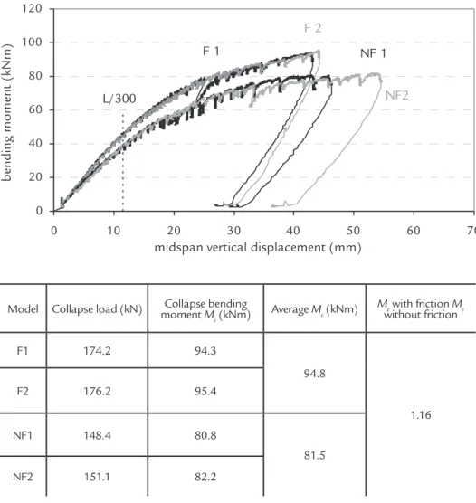
Figure 6 presents the beam responses in terms of bending moment x delection at midspan section for all four tested models. It was possible to observe the favorable inluence of friction to the beam stiffness and resistance. Collapse loads and bending moments can be found in Table 1, where
it is shown that the ratio between the average collapse bending moments of the beams with friction and without friction achieved 1.16. This result was obtained for proiles with a painted surface, which means that higher values are expected for the untreated surface. Once the service
bending moment is deined as the one as-sociated with the limit delection equal to L/300, it can be noticed in Figure 6 that this moment corresponds to 46 kN.m for the beam with friction and to 40 kN.m to beam without friction, a difference of 11% assigned to the favorable effect of friction.
Figure 6
Bending moment deflection curves for the four models tested (Oliveira, 2009). 0
20 40 60 80 100 120
0 10 20 30 40 50 60 70
midspan vertical displacement (mm)
bending moment (kNm)
NF2
F 1 NF 1
L/300
F 2
Model Collapse load (kN) moment Collapse bending M c (kNm)
Average Mc (kNm) Mc
with friction Mc without friction
F1 174.2 94.3
94.8
1.16
F2 176.2 95.4
NF1 148.4 80.8
81.5
NF2 151.1 82.2 Table 1
Collapse load and bending moment Mc
3. Numerical model
A inite element model was devel-oped allowing elastic and plastic analy-ses of simple or continuous composite beams, including friction at the inter-face, with any type of loading applied to the slab or to the I section proile. The software ANSYS version 11.0 and the following elements were used (see Figures 7):
1. Solid 65 – used to model the concrete slab; material modeling for compression consists of multilinear stress-strain curve and the Von Mises yield criterion (avoiding any stiffness degradation due to concrete crushing); William & Warnke failure model allow-ing for crackallow-ing in the tension zone was adopted.
2. Shell 181 – used to model the
steel proile, with Von Mises criteria, multilinear stress-strain relation and kinematic hardening;
3. Link 8 – auxiliary elements used to model the shear connector spring at the slab center level ;
4. Link 10 – tension resistant only, used to avoid vertical separation between slab and steel proile;
5. Contac 12 – used to model the friction at the interface between slab and steel proile;
6. Combin 39 – nonlinear spring element used to model the load-slip curve of the shear connectors.
The 87.5cm width concrete slab was modeled with 4 layers of solid ele-ments across its 6.5 cm thickness. The transversal reinforcing bars were
con-sidered as smeared throughout the solid inite elements of the two upper layers while the longitudinal ones were mod-eled within the elements in the region of their locations. Multilinear kinematic hardening model and Von Mises yield criterion are used for the rebars.
In the solution of the system of equations, incremental load steps varied in the range between 0.01 and 0.015% of the ultimate load.
In a previous study, a less reined numerical model was developed to simulate the experimental tests in which shell elements were used to discretize the
slab (QUEIROZ et al., 2010). Concrete
stiffness degradation after cracking in the tension zone was not considered in this model.
257
4. Comparisons between numerical and experimental results
The models of series F and NF tested at the laboratory were simulated with the inite element models described in section 3. For that purpose the CFP box section was transformed to an equivalent I shape. Figure 4 shows the connectors load slip curve (in dotted line) adopted in the numerical model.
The curve itted to the experimental results was further adjusted to consider the lower number of shear connectors of the numerical model in each beam side (17 connectors) as compared to the physical model (22 connectors).
Figure 8 shows the comparison be-tween the experimental results from the
tests with and without friction and their numerical counterparts obtained with two models: the one described in sec-tion 3 in which solid elements were used to simulate the slab (“slab solid65) and the model presented in a previous study where shell elements represented the slab (“slab shell”).
Figure 8 Comparison between numerical
and experimental results.
In both simulations, with and with-out friction, the “slab solid65” model displayed convergence problems and the analyses were precociously interrupted. Nevertheless, it can be noticed in Fig 8a that the result obtained with this model displayed a very good correlation with the NF1 test, without friction. For the case with friction (Fig. 8b), the behavior of the beam was well simulated by this model un-til half collapse load approximately; after
that load the numerical model presented greater lexibility than the experimental one. This can be explained by problems of friction simulation in the numerical model which, in this case, led to a signiicant dif-ference in the results.
For the test without friction (Fig. 8a), the numerical model “slab shell” displayed a more rigid behavior than the model “slab solid65” and the physical model due to a poor simulation of the slab material,
which does not take into account stiff-ness degradation after concrete cracking. On the other hand the simulation of the beam with friction (Fig.8b) seems to show a very good correlation with the experi-mental results but in this case two opposite effects contribute to this performance: the absence of the steel proile sheeting in the numerical model and the lack of appropriate modelling of the concrete in tension regions.
ELEMENTS MAT NUM
NV
(a)
(b) (c)
slab C
Lcombin39
contac 12
profile top
link 8
link 10
link 8
Figure 7 Finite Element model using solid
elements to simulate the slab. (a) general view; (b) detailed view; (c) elements at the concrete-steel interface.
5. Conclusions
The results of experimental tests in simple composite beams showed that
friction at the interface between the slab and the steel proile plays an important
ABNT - Associação Brasileira de Normas Técnicas, Projeto e execução de estruturas de aço e de estruturas mistas aço e concreto de edifícios. NBR 8800, São Paulo, Brasil, 2008.
AISC - American Institute of Steel Construction, Load and Resistance Factor Design Speciication for Structural Steel Buildings, Chicago, 2005.
ANSYS Version 11.0. Documentation. ANSYS, Inc.
BREMER C.F. Vigas mistas em peris formados a frio com lajes mis-tas e lajes moldadas sobre painéis de concreto celular, Belo Horizon-te: Universidade Federal de Ouro Preto, 2007. (D. Sc. Thesis).
OLIVEIRA, C.G.R. Análise teórico-experimental de vigas mistas com peril formado a frio, lexibilidade dos conectores de cisalhamento e a inluência do atrito entre o concreto e o aço do peril, Belo Horizonte: Universidade Federal de Minas Gerais, 2009. (M.Sc Thesis)
QUEIROZ, G, RODRIGUES, F, PEREIRA, S; PFEIL; M; OLIVEIRA; C; MATA; L. Behavior of steel-concrete composite beams with lexible shear connectors, In: Proc. Stability and Ductility of Steel Structures (SSDS’Rio 2010), vol.1, p.863-870, Rio de Janeiro, 2010.
QUEIROZ, G., PEREIRA, S.S.R; MATA, L.A.C., SILVA, M., Inluence of friction at the slab/steel proile interface and of the lexibility of shear connectors in steel – concrete composite beams, In: EUROMECH SOLID MECHANICS CONFE-RENCE, 7th .Lisbon, 2009.
SILVA M.C. Análise numérica de vigas mistas levando em conta a lexibilidade e a ductilidade dos conectores de cisalhamento bem com o atrito na interface entre o aço e o concreto, Belo Horizonte: Universidade Federal de Minas Gerais, 2009. (M.Sc. Thesis)
Received: 20 March 2013 - Accepted: 25 July 2014.
7. References
6. Acknowledgments
The authors gratefully acknowl-edge the inancial support received from
FAPEMIG (Fundação de Amparo à Pesquisa do Estado de Minas Gerais). 3.5m span tested beams with connectors
composed by bolts threaded to rivets, a 16% increase in collapse bending moment was assigned to the friction favorable effect. It became evident that not only the connector strength but also the connector stiffness should be considered in the design, speciically in delection evaluation.
The two numerical models de-veloped to simulate the behavior of the tested beams exhibited very good correlations with the experimental results until approximately half col-lapse load. After that point, issues like concrete modelling in the tension zone and the absence of the proile sheeting in the numerical models contribute to a