Repositório ISCTE-IUL
Deposited in Repositório ISCTE-IUL: 2019-01-07
Deposited version: Post-print
Peer-review status of attached file: Peer-reviewed
Citation for published item:
Viegas, V., Dias Pereira, J. M., Postolache, O. & Girão, P. M. (2018). Spy walker: a convenient way to assess gait in walker assistive devices. In 2018 IEEE International Instrumentation and Measurement Technology Conference, I2MTC 2018. (pp. 1-6). Houston: IEEE.
Further information on publisher's website: 10.1109/I2MTC.2018.8409570
Publisher's copyright statement:
This is the peer reviewed version of the following article: Viegas, V., Dias Pereira, J. M., Postolache, O. & Girão, P. M. (2018). Spy walker: a convenient way to assess gait in walker assistive devices. In 2018 IEEE International Instrumentation and Measurement Technology Conference, I2MTC 2018. (pp. 1-6). Houston: IEEE., which has been published in final form at
https://dx.doi.org/10.1109/I2MTC.2018.8409570. This article may be used for non-commercial purposes in accordance with the Publisher's Terms and Conditions for self-archiving.
Use policy
Creative Commons CC BY 4.0
The full-text may be used and/or reproduced, and given to third parties in any format or medium, without prior permission or charge, for personal research or study, educational, or not-for-profit purposes provided that:
• a full bibliographic reference is made to the original source • a link is made to the metadata record in the Repository • the full-text is not changed in any way
The full-text must not be sold in any format or medium without the formal permission of the copyright holders.
Serviços de Informação e Documentação, Instituto Universitário de Lisboa (ISCTE-IUL) Av. das Forças Armadas, Edifício II, 1649-026 Lisboa Portugal
Phone: +(351) 217 903 024 | e-mail: administrador.repositorio@iscte-iul.pt https://repositorio.iscte-iul.pt
Spy Walker
A Convenient Way to Assess Gait in Walker Assistive Devices
Vítor Viegas(1,2), J. M. Dias Pereira(1,2) (1) ESTSetúbal/IPS, Setúbal, Portugal (2) Instituto de Telecomunicações, Lisbon, Portugal
Email: vitor.viegas@estsetubal.ips.pt
Octavian Postolache(2,3), Pedro Silva Girão(2,4) (2) Instituto de Telecomunicações, Lisbon, Portugal
(3) ISCTE-IUL, Lisbon, Portugal
4) DEEC/Instituto Superior Técnico, Lisbon, Portugal
Abstract – This paper presents the Spy Walker, a measurement
system intended to characterize gait in walker assistive devices. The proposed system can be easily integrated into any commercial walker without any loss of native functionality. The system makes use of e-textile electrodes to sense the heart rate of the user, load cells to measure the force applied on the walker legs, and an inertial measurement unit to sense motion and orientation. These signals are sampled locally and then transferred over a Bluetooth link to a remote host where they are processed in real time. Data processing includes the detection, classification and characterization of steps. A rich set of parameters is presented for each step, including estimates of unbalance and motor incoordination, travelled distance and azimuth, and lift of the walker frame. This information can be used by a physiotherapist to assess objectively the physical condition of the user, and tune the rehabilitation therapy if needed.
Keywords – walker assistive device; gait analysis; heart rate; load cell; IMU.
I. INTRODUCTION
Assistive walking devices play an important role in extending the autonomy and quality of life of elderly people. They are also key elements in recovering the mobility of people affected by locomotion disabilities due to amputation, injuries of spine, muscular dystrophies or other causes.
Walkers, in particular, increase the support base of elderly people and help them to stay balanced. This assistance reduces the costs associated with accidental falls, thus contributing to the sustainability of the medical care system [1,2]. Walkers also help increasing the confidence levels of the patient during long-term rehabilitation therapies. Vogt el al. [3] showed that the use of rollators (walkers with wheels) does not affect the therapy results and accelerates the recovery time.
In many walker-related studies, the evaluation of the user’s balance and motor coordination is usually based on subjective data acquired through human observations. In order to improve the evaluation process, instrumented walkers have been proposed by several research groups. Bachschmidt et al. [4] developed an instrumented walker equipped with six strain-gauges to sense the forces applied on the walker legs and handgrips. Chan et al. [5] presented a rollator capable of measuring distance, velocity and the forces applied on the handgrips. In both cases, the goal was to monitor the physical condition of the user and analyze the walker usage.
Our team [6,7,8] has been working on smart walkers over the last years. We’ve tried a vast set of sensors, including force sensing resistors and load cells to measure force, and LIDAR and microwave Doppler RADAR to measure distance and velocity. Our purpose is to evaluate the proper usage of the assistive device, and to extract gait parameters to understand how the rehabilitation therapy is progressing over time.
In this paper we present the Spy Walker, our last proposal for a smart walker. It includes e-textile electrodes to detect user’s heart rate, load cells to measure the forces applied on the walker legs, an Inertial Measurement Unit (IMU) to sense motion and orientation, and software to bind all things together. The work was done on a standard four-leg walker, but it can be easily extended to other kinds of walkers. Care was taken to preserve the native functionality of the device and to reduce the upgrade costs.
The paper is organized as follows: section II defines the geometry and metrics used along the paper; section III describes the implemented measurement system; section IV presents experimental results; and section V draws conclusions.
II. PRELIMIAR DEFINITONS
The next paragraphs define a Cartesian coordinate system to represent the walker frame, and two indexes to characterize user’s gait.
A. Unbalance Index
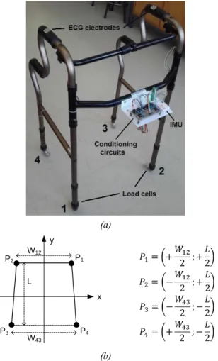
Balance has to do with the distribution of forces applied on the walker legs. Considerer the coordinate system illustrated in Fig. 1, where the walker legs are numbered from 1 to 4 (as quadrants) and the y-axis points to the forward direction. According to this arrangement, the center of forces (COF) is given by: 𝐶𝑂𝐹𝑥 = 𝑊12(𝐹1−𝐹2)+𝑊43(𝐹4−𝐹3) 2(𝐹1+𝐹2+𝐹3+𝐹4) 𝐶𝑂𝐹𝑦= 𝐿(𝐹1−𝐹4)+𝐿(𝐹2−𝐹3) 2(𝐹1+𝐹2+𝐹3+𝐹4)
where Fk represents the force applied on each leg, W12 and W43
represent the distances between the front and rear legs respectively, which corresponds roughly to the mean walker width (W), and L represents the distance between the front and rear legs, which corresponds to the walker length.
(a) y x W43 P1 P2 P3 P4 W12 L 𝑃1= (+ 𝑊12 2 ; + 𝐿 2) 𝑃2= (− 𝑊12 2 ; + 𝐿 2) 𝑃3= (− 𝑊43 2 ; − 𝐿 2) 𝑃4= (+ 𝑊43 2 ; − 𝐿 2) (b)
Fig. 1. Coordinate system of the measurement system: a) Four-leg walker; b) Cartesian plane and coordinates of the walker legs.
We define the unbalance index (I1) as the deviation of the
COF in relation to the geometrical center of the walker polygon:
𝐼1(%) = 100 ×
√(𝐶𝑂𝐹𝑥)2+(𝐶𝑂𝐹𝑦)2
√(𝑊/2)2+(𝐿/2)2 × 𝛼
with being given by:
𝛼 =𝐹1+𝐹2+𝐹3+𝐹4
𝐹𝑈 =
𝐹𝑇
𝐹𝑈
where FT represents the total force applied on the walker legs
and FU represents the user weight. Alpha () is a weighting
factor that varies between 0 (walker resting) and 1 (walker full charged with the user weight).
B. Motor Incoordination Index
Motor coordination has to do with the right sequence of movements needed to complete a step. Considerer the state machine illustrated in Fig. 2, where the states represent the gait phases and the continuous arrows represent normal transitions between states [9,10]. If the user completes a step passing through all the gait phases, the step is classified as good; otherwise is classified as bad.
We define the incoordination index (I2) as the number of
bad steps (B) in the last N steps:
𝐼2(%) = 100 × 𝐵
𝑁
III. MEASUREMENT SYSTEM
The measurement system includes a wireless data acquisition module, an IMU, a heart rate sensor, four load cells and software to process data and extract meaningful information.
A. Data Acquisition Module
The data acquisition module, model Shimmer3 [11] from Shimmer Sensing, is the central hub where all the sensors are connected. Wires pass nicely through the tubular structure of the walker without any loss of functionality. The module includes an embedded IMU and a four-input extension board where the external sensors are connected (AI1-AI4). Samples from all sensors (IMU and external) are acquired at a rate of 51.2 S/s and sent to a remote host through a Bluetooth link.
B. Inertial Measurement Unit
The embedded IMU is used to sense motion and orientation. It has nine degrees of freedom (9DoF) given by a 3-axes accelerometer (model KXRB5-2042 from Kionix), a 3-axes gyroscope (model MPU-9150 from Invensense) and a 3-axes magnetometer (model LSM303DLHC from STMicroelectronics).
Fig. 2. Gait Phases (GP) during a walker step (the polygon delimits the support area). GP0: the walker is resting on the floor; GP1: the walker is flying; GP2: the walker is on the floor waiting for the injured foot to move forward; GP3: the injured foot is moving forward; GP4: waiting for the healthy foot to move forward; GP5: the healthy foot is moving forward.
The IMU has a pre-defined coordinate system that associates the x, y and z axes to the length, width and height of its case, respectively. The IMU is placed horizontally so that the accelerations across the x and y axes give motion over the plan, while the acceleration across the z axis, subtracted by 1 g = 9.81 ms-2, gives motion in the vertical.
The IMU also runs a gradient descent algorithm [12] that gives the orientation of the device in absolute ENU coordinates (local East-North-Up). This allows us to know the azimuth of the walker, where {0°, 90°, 180°, 270°} corresponds to {north, east, south, west} respectively.
All the sensors must be calibrated in advance to cancel offset errors and tune gain matrices. The calibration procedure [13] is executed once and the results are saved into a non-volatile memory.
C. Heart Rate Sensor
Two dry e-textile electrodes, placed on the walker handgrips, are used to acquire the electrocardiogram signal (ECG) of the user. The electrodes are tied with a tiny Velcro strip making them removable and washable. Since the electrodes seem like ordinary cloth, they don’t introduce additional stress to the user.
The ECG signal is conditioned by an analog front-end based on the AD8232. The signal passes through a two-pole band-pass filter, with cutoff frequencies at 7 Hz and 24 Hz, followed by an amplifier with gain 1000. The narrow-band filter eliminates motion artifacts and line noise but distorts the ECG waveform significantly, making it suitable only for heart-rate detection. The output signal is connected to the first analog input (AI1) of the data acquisition module.
D. Force Sensors
Four load cells are used to sense the forces applied on the walker legs. Each cell is attached to the extremity of a leg using a dedicated plastic adapter grown on a low-cost 3D printer (see Fig. 3).
Each load cell contains four strain gauges fixed to a small bending beam (55.3 x 12.7 x 12.7 mm) that supports 20 kgf. Other characteristics include: rate output = 10.15 mV/V, non-linearity = 0.05% FS and hysteresis = 0.05% FS. The use of bending beam load cells is justified because they are much cheaper than inline/axial load cells.
Fig. 3. Load cell attached to the walker leg.
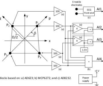
The load cells are supplied at 3 V and conditioned by instrumentation amplifiers with gain 100. The voltages are then combined in pairs, subtracted from each other (1-3 and 2-4),
amplified by 4 and biased around 1.5 V, as shown in Fig. 4. The result is a voltage that varies linearly between 0.3 V and 2.7 V for forces applied along the auxiliary axes p and q, between −𝐷/2 and +𝐷/2, where 𝐷 = √𝐿2+ 𝑊2 is the walker
diagonal. The coordinates over these axes are given by:
𝑃[mm] =𝐷[mm]
2.4 × 𝐴𝐼2[V] − 0.625 × 𝐷[mm] (6)
𝑄[mm] =𝐷[mm]
2.4 × 𝐴𝐼3[V] − 0.625 × 𝐷[mm] (7)
The conversion to x and y coordinates is done by taking advantage of the left/right symmetry of the walker:
𝐶𝑂𝐹𝑥[mm] = (𝑃 − 𝑄) × cos 𝛽 (8)
𝐶𝑂𝐹𝑦[mm] = (𝑃 + 𝑄) × sin 𝛽 (9)
where 𝛽 = tan−1(𝐿
𝑊) is the angle made by the walker diagonal.
Additionally, the voltages from the load cells are all summed together to give the total load applied on the walker. Knowing that the maximum weight, given by 4 x 20 = 80 kgf, corresponds to 1.2 V, we get:
𝐹𝑇[kgf] = ( 80
1.2) × 𝐴𝐼4[V] (10)
All this effort is needed because the data acquisition module has only four analog inputs for five sensors. Playing with the walker symmetry, together with some basic trigonometry, we were able to eliminate the need for a fifth input.
y x 1.5V P1 P2 P3 P 4 AI4 b p q 4 + -100 100 100 100 4 + -+ + + AI3 AI2 AI1 ECG front end E-textile electrodes (a) (a) (a) (a) (a) (a) (b) (c) D/2 Power supply +3 V
Blocks based on: a) AD623; b) MCP6272; and c) AD8232.
Fig. 4. Signal conditioning circuitry.
E. Data Processing
Data processing is done by the application Spy Walker that runs on the host side. The application was developed in Visual Studio 2012 and makes use of Shimmer C# API [14] to interact with the Shimmer3 module.
Data processing includes the following main tasks: 1. Computation of the heart rate from the signal connected
to AI1. A simple Schmitt-trigger algorithm, with fixed thresholds at 0.5 V and 1 V, is executed to detect the heart beats. The time elapsed between beats is inverted to give the heart rate.
2. Computation of COFx and COFy from the signals
connected to AI2 and AI3. This is done by solving equations (6), (7), (8) and (9), by this order.
3. Computation of the unbalance index (I1) taking into
account the signal connected to AI4. This is done by solving equations (10), (4) and (3), by this order. 4. Detection of bad steps (B) by running the state machine
represented in Fig. 5.
5. Computation of the motor incoordination index (I2) by
solving equation (5).
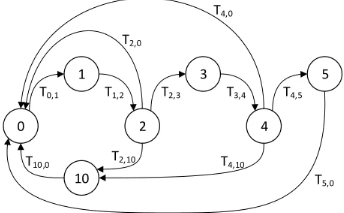
The state machine illustrated in Fig. 5 is a key element of the smart walker because it classifies steps as good or bad. States 0 to 5 represent the gait phases (as in Fig. 2) and state 10 represents a waiting state to rearm the machine. Transitions between states (Tfrom,to) are triggered by sensor measurements
as follows:
• T0,1 is enabled if FT < WEIGHT_TH. This transition
occurs when the total force measured by the load cells falls below a given threshold (below the walker weight). In other words, it occurs when the walker is lifted in the air, at the beginning of a new step.
• T1,2 is enabled if FT > WEIGHT_TH. This transition
occurs when the walker touches down the floor again. • T2,3 is enabled if COFx > RIGHT_TH or COFx <
LEFT_TH depending on which foot is injured (left or right, respectively). This transaction occurs when the user moves forward the injured foot and applies force on the opposite side. The injured foot shall be the first to move forward. The type of disability must be defined in advance to determine the threshold value.
• T3,4 is enabled if COFx < RIGHT_TH or COFx >
LEFT_TH depending on which foot is injured (left or right, respectively). This transaction occurs when the user alleviates the force previously applied to the walker, i.e., when COFx returns to the origin.
• T4,5 is enabled if COFx < LEFT_TH or COFx >
RIGHT_TH depending on which foot is injured (left or right, respectively). This transaction occurs when the user moves forward the healthy foot and applies force on the opposite side. The healthy foot shall be the last to move forward.
• T5,0 is enabled if COFx > LEFT_TH or COFx <
RIGHT_TH depending on which foot is injured (left or right, respectively). This transaction occurs when COFx
returns to the origin.
• T2,0 and T4,0 are enabled if COFx moves to the wrong
side, i.e. if the user moves forward the wrong foot. The machine returns to state 0 and waits for a new step. • T2,10 and T4,10 are enabled if FT < WEIGHT_TH. This
transition occurs if the user lifts up the walker before finishing the step. In other words, it occurs if the user aborts the step.
• T10,0 is enabled if FT > WEIGHT_TH. This transition
occurs when the walker touches down the floor again. The machine returns to state 0 and waits for a new step. A step is marked as good if the machine passes through all the states from 0 to 5. A step is marked as bad if the user aborts it or moves forward the wrong foot.
The threshold WEIGHT_TH is fixed and equal to half of the walker weight. The thresholds RIGHT_TH and LEFT_TH are dynamic and computed according to the following instructions:
(11) { 𝐿𝐸𝐹𝑇_𝑇𝐻(0) = −𝑊 6 𝐿𝐸𝐹𝑇_𝑇𝐻(𝑘) =𝑚𝑖𝑛𝐶𝑂𝐹𝑥(𝑘−1) 2 If (𝐿𝐸𝐹𝑇_𝑇𝐻(𝑘) > −50 mm) 𝐿𝐸𝐹𝑇_𝑇𝐻(𝑘) = −50 mm (12) { 𝑅𝐼𝐺𝐻𝑇_𝑇𝐻(0) = +𝑊 6 𝑅𝐼𝐺𝐻𝑇_𝑇𝐻(𝑘) =𝑚𝑎𝑥𝐶𝑂𝐹𝑥(𝑘−1) 2 If (𝑅𝐼𝐺𝐻𝑇_𝑇𝐻(𝑘) < +50 mm) 𝑅𝐼𝐺𝐻𝑇_𝑇𝐻(𝑘) = +50 mm
where k represents the kth good step, and min/maxCOFx(k-1)
represents the minimum/maximum value reached by COFx
during the previous (k-1) good step.
0 1 2 10 T0,1 T1,2 T10,0 T2,10 3 4 T2,3 5 T3,4 T4,5 T4,10 T2,0 T4,0 T5,0
Fig. 5. State machine used to identify good and bad steps.
F. Data Visualization
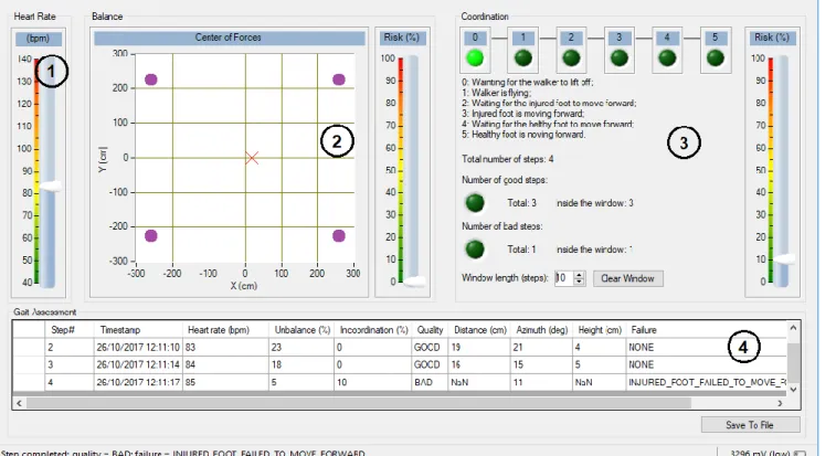
Processed data is shown, namely to a physiotherapist, through the graphical interface shown in Fig. 6, which consists of four main panels:
• Panel 1: Shows the instantaneous value of the user’s heart rate. This is useful to estimate the effort and stress felt by the user.
• Panel 2: The COF is computed, and the result is presented as a red cross moving over a XY graph. When the user loads his left side the cross moves toward negative values of X; otherwise, the cross moves toward positive values of X. The same applies for the front/back direction over the Y axis, much like a joystick. A vertical slider shows the instantaneous value of the unbalance index (I1).
• Panel 3: A set of six LEDs are turned on sequentially while the state machine moves forward from state 0 to state 5. If the user passes through all the gait phases successfully, all the LEDs end up lighted and the step is marked as good. If the user violates any gait phase, the machine is reset to state 0 and the step is marked as bad. The number of good and bad steps is registered. A vertical slider shows the instantaneous value of the motor incoordination index (I2).
• Panel 4: Presents a list of all steps detected. For each step the following information is provided: timestamp (date and time), maximum heart rate, maximum unbalance (I1max), motor incoordination (I2), quality
(GOOD or BAD), travelled distance, azimuth, lift of the walker frame while moving forward, and failure (NONE, STEP_ABORTED, INJURED_FOOT_ FAILED_TO_MOVE_FORWARD, HEALTHY_ FOOT_FAILED_TO_MOVE_FORWARD). The physiotherapist can also add free comments to each step. The list can be saved to a text file in the tsv format.
IV. EXPERIMENTAL RESULTS
Experimental tests were carried by a user with impaired gait caused by an injury in the right lower limb. A standard four-leg walker was used (shown in Fig. 1a), with a weight equal to 2 kg and dimensions W12 = 512 mm, W43 = 530 mm and L = 445
mm.
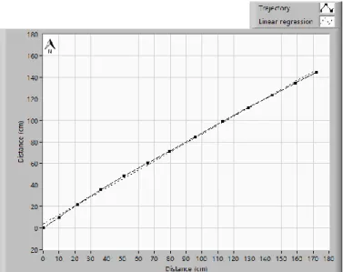
Fig. 7 shows the trajectory followed by the user after being instructed to follow an imaginary straight line. The XY graph covers 12 steps, with each step being represented by a line segment. The length and angle of the segment represent the travelled distance and azimuth of the walker. The user moves from the origin (0,0) to the periphery. The positive y-axis points to the magnetic north (azimuth = 0º).
During the test, the user followed a trajectory almost linear with a mean squared error equal do 3.5 cm. The step length had an average value of 18.8 cm and a standard deviation equal to 2.2 cm. The walker was lifted 4.9 cm in average, with a standard deviation equal to 1.0 cm. The average heart rate was about 84 bpm, and the indexes for unbalance and motor incoordination did not exceed 25% and 10%, respectively. All these values suggest a stress-free, regular gait, with good control of movements.
Fig. 7. User walking towards northeast (approximately).
Fig. 8 plots the number of good and bad steps inside a moving-window during a sequence of 20 steps. The window starts empty and covers the last 10 steps. It becomes full at the 10th step, with 2 bad and 8 good steps, which gives a value of
20% for I2. Thereafter, the value of I2 increases when a bad step
is detected and a good step leaves the window; decreases when a good step is detected and a bad step leaves the window; and remains constant if both steps (entering and leaving the window) have the same quality.
The state machine worked well with few false bads. There were no false goods because the validation of a good step is quite demanding.
Fig. 8. Motor incoordination during a sequence of 20 steps.
V. CONCLUSIONS
The experimental results show that our prototype is able to detect and classify steps on a standard four-leg walker. Each step is characterized by a rich set of parameters, including estimates of unbalance and motor incoordination, travelled distance, azimuth and lift. This record of information can be used by a physiotherapist to assess objectively the physical condition of the user. If these records are saved during multiple sessions, the physiotherapist can look at them, understand how the rehabilitation therapy is progressing over time, and take corrective actions if needed.
ACKNOWLEDGMENT
The work was supported by Instituto de Telecomunicações and Fundação para a Ciência e Tecnologia, project PTDC/DTP-DES/6776/2014.
REFERENCES
[1] Sara M. Bradley, Cameron R. Hernandez, “Geriatric assistive devices”, Am Fam Physician, Issue 15, No. 84(4), pp. 405-411, August 2011. [2] S. R. Faruqui, T. Jaeblon, “Ambulatory assistive devices in orthopedics:
uses and modifications”, J Am Acad Orthop Surg., Issue 18, No. 1, pp. 41–50, 2010.
[3] L. Vogt, K. Lucki, M. Bach, W. Banzer, “Rollator use and functional outcome of geriatric rehabilitation”, J Rehabil Res Dev, Issue 47, No. 2, pp. 151-156, 2010.
[4] R.A. Bachschmidt, G.F. Harris, G.G. Simoneau, “Walker-assisted gait in rehabilitation: a study of biomechanics and instrumentation”, IEEE Transactions on Neural Systems and Rehabilitation Engineering, Vol. 9, Issue 1, pp. 96 – 105, 2002.
[5] A.D.C. Chan, J.R. Green, “Smart rollator prototype”, IEEE International Workshop on Medical Measurements and Applications (MeMeA), May 9-10, Ottawa, Canada, 2008.
[6] O. Postolache, P. Girão, J. M. Dias Pereira, G. Postolache, "Smart walker for pervasive healthcare", Proceedings of International Conference on Sensing Technology (ICST), Palmerston North, New Zealand, Vol. 1, pp. 1-5, December 2011.
[7] O. Postolache, J. M. Dias Pereira, V. Viegas, P. Girão, "Gait rehabilitation assessment based on microwave doppler radars embedded in walkers", IEEE International Workshop on Medical Measurements and Applications (MeMeA), Torino, Italy, May 2015.
[8] J. M. Dias Pereira, Vítor Viegas, Octavian Postolache, Pedro Silva Girão, “Combining distance and force measurements to monitor the usage of walker assistive devices”, IEEE International Instrumentation and Measurement Technology Conference (I2MTC), Torino, Italy, May 2017. [9] David A. Winter, “Biomechanics of Normal and Pathological Gait: Implications for Understanding Human Locomotor Control”, Journal of Motor Behaviour, Vol. 21, No. 4, pp. 337-355, December 1989. [10] Marder E, Calabrese RL, “Principles of Rhythmic Motor Pattern
Generation”, Physiolical Reviews, Vol. 76, Issue 3, 1996 Jul, 76(3):687– 717.
[11] www.shimmersensing.com/products/shimmer3-imu-sensor (accessed the 30th of October 2017)
[12] Sebastian O.H. Madgwick, Andrew J.L. Harrison, Ravi Vaidyanathan, “Estimation of IMU and MARG orientation using a gradient descent algorithm”, IEEE International Conference on Rehabilitation Robotics, Zurich, Switzerland, June 29 - July 1, 2011.
[13] “9DoF Calibration Application User Manual Rev. 2.5a”, Shimmer, 2014. [14] “Shimmer C# API”, http://www.shimmersensing.com/products/