SUMMARY
This paper analyses durability aspects related to the use of reinforced micro-concrete as strengthening material of ancient rubble stone masonry walls. The present study is a section of a research project carried out at the New University of Lisbon (Pinho, 2007), to evaluate some structural strengthening solutions for rubble stone masonry buildings. These kind of strengthening solutions, using sprayed micro-concrete layers (shotcrete layers), are very common in Portugal, namely in the rehabilitation of ancient buildings, as may be seen in Azores, after the earthquake of 1998.
1. INTRODUTION
The main objective of the mentioned research (Pinho, 2007) was the mechanical evaluation of different strengthening solutions applied on rubble stone masonry walls. Different strengthening solutions have been applied over several rubble stone masonry models. Besides, some durability aspects related to the ancient wall materials (sands, limes, mortars and stones) and to the strengthening materials (micro-concrete and steel reinforcement, in this case) were considered. This paper will analyse the main aspects related to the durability conditions of two of the strengthening solutions applied on the experimental models: solutions II and III, where sprayed micro-concrete layers (shotcrete) were used as strengthening material (solution often used in Portugal). The experimental results of the tests carried out to find some physical and mechanical characteristics of the masonry and the shotcrete are considered and discussed. The experimental results presented in the paper, in terms of physical characteristics, are water capillarity, water vapour permeability and open porosity values, performed both on masonry mortar and shotcrete samples, and water absorption under low pressure, carried out directly on masonry models (simple models) and on the micro-concrete of the strengthened models. Mechanical characteristics, in terms of flexural and compressive resistance and elasticity modulus, are also evaluated.
The way how shotcrete affect or can be affected by the ancient rubble stone masonry walls, namely in terms of their behaviour in the presence of water (vapour or liquid), which can start physical, mechanical and chemical degradation mechanisms, are analysed. The chemical mechanisms implicated on the degradation of the masonry and the shotcrete, obtained in specific bibliography, are synthesized: the behaviour of the strengthened walls in the presence of salts, namely sulphates and chlorides, is specifically discussed. Preventive actions to avoid degradation of the strengthened walls, when these kinds of solutions are applied, are also discussed.
The mechanical behaviour of strengthening solutions II and III are presented to this International Seminar in another paper.
2. EXPERIMENTAL CAMPAIGN
For this research (Pinho, 2007) several rubble stone masonry models were constructed according with ancient techniques (Nero et al, 1994; Pinho, 2000; Valluzzi et al, 2001, Veiga et al, 2001), divided into two groups: twenty models with 1,20m high, 1,20m wide and 0,40m thick (large models), for shear-compression load tests, and forty two models with 1,20m high, 0,80m wide and 0,40m thick (small models) for compression load tests. Three models of each group were tested without strengthening (unreinforced masonry – URM) and some others (some of them were not tested yet) with the following strengthening solutions (Pinho et al, 2004): (i) solution I –
DURABILITY ASPECTS RELATED TO RUBBLE STONE MASONRY WALLS
STRENGTHENED WITH REINFORCED MICRO-CONCRETE LAYERS
Fernando F. S. Pinho, Válter J. G. Lúcio & Paulina Faria
Universidade Nova de Lisboa, Departamento de Engenharia Civil, Lisboa, Portugal Manuel F. C. Baião
continuous transversal steel connectors (only); (ii) solution II – shotcrete lateral layer, 5 cm thick, reinforced with steel expanded mesh, transversal ties through the thickness of the models (continuous steel connectors and short steel anchors), without contact to the base of the loading systems; (iii) solution III – shotcrete lateral layer, 5 cm thick, reinforced with steel expanded mesh, with and without continuous transversal steel ties, but with contact to the loading system base; and (iv) solution IV – lime and cement mortar rendering, 3 cm thick, reinforced with glass fibre mesh, transversal ties of zinc coated steel wires, and with base contact. Some of the models were also used for water absorption tests under low pressure.
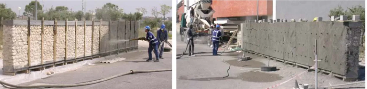
Figure 1 shows two general views of the construction of the experimental models using traditional techniques, and geometrical characteristics of the models.
a - concrete lintel; b - rubble stone masonry; c - concrete base; d - support of the models
Figure 1 – Geometry of the experimental rubble stone masonry models and views of their construction, using traditional techniques
Figure 2 presents a general view of the application of solution II (similar to solution III) – first and second shotcrete layers, which durability aspects are analysed in this paper.
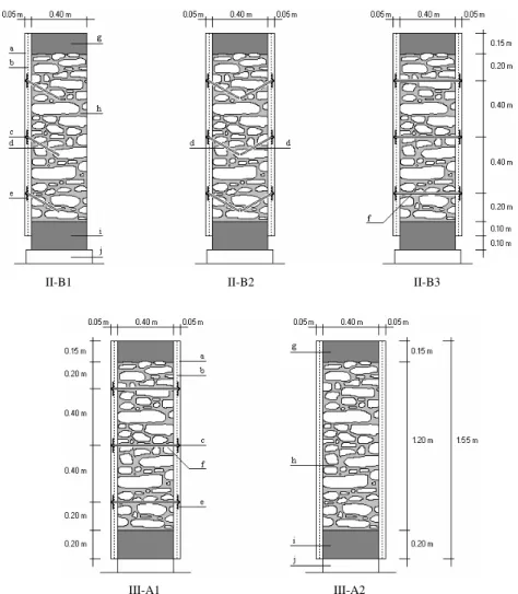
In Figure 3 the geometrical characteristics of both strengthening solutions analysed in this article are presented: solution II, including its three variants (B1, B2 and B3), and solution III, including its two variants (A1 and A2).
II-B1 II-B2 II-B3
III-A1 III-A2
a – shotcrete lateral layer (5 cm total thick); b – steel expanded mesh; c – screw-nut; d – screwed steel bar (short steel anchors in this configuration, with 30º leaning); e – metallic plate with 100×100 mm2 and 5 mm thick; f – screwed steel bar
(continuous transversal steel connectors, in this configuration); g – concrete lintel; h – ruble stone masonry; i – concrete base; j – supports of the models
Figure 3 – Detailing of both strengthening solutions II and III
2. DURABILITY ASPECTS RELATED TO RUBBLE STONE MASONRY WALLS STRENGTHENED WITH SHOTCRETE LAYERS
2.1. Context of the problem
the consolidation implemented on the walls is done with durable materials and techniques but that will not contribute to the degradation process of the wall itself. The characteristics needed to assure the protection of the walls should then be identified and evaluated to assure the durability of such strengthening solutions and materials.
2.2. Degradation aspects in the rubble stone masonry
Concerning to the masonry (URM), the main physical and mechanical degradation mechanisms are caused by the water due to its movement in the middle of the structural elements (foundations and walls), from the core to the surface, where it evaporates. The water dissolves and transports soluble salts through the masonry; hygroscopic salts change their volume with hygrometric variations; higher volumes of the salts impose stresses in the masonry material pores.
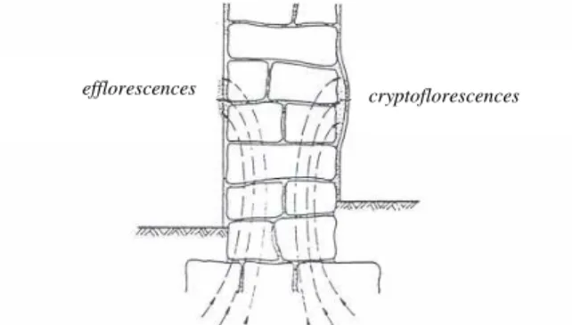
The degradation corresponds mainly to disaggregation phenomena due to the loss of lime from the old mortars along time and to the cyclic expansion/contraction actions caused by the crystallization and dissolution of the “coming” salts (transported by the water) inside the masonry, or behind less vapour permeable renderings (cryptoflorescences) or at its surface (efflorescences), figure 4. Generally these salts are: (i) chlorides, which exist particularly in coastal environments; (ii) nitrates, which are common when biological contamination is present (soil with animals contamination, drain sewers contamination) and (iii) sulphates present in building materials, like gypsum, and polluted ambiances.
Figure 4 – Development of efflorescences and cryptoflorescences phenomena (Silva, 1983)
Disaggregation phenomena could be caused by cyclic expansive reactions inside the masonry or between its surface and the shotcrete layers (strengthened masonry) or other less vapour permeable rendering, reducing the mechanical resistance of the ancient wall and the global durability conditions of both masonry and shotcrete. The damage grows because normally the phenomena have cyclic and seasonal characteristics. When cryptoflorescences happen, the disaggregation develops behind the surface (shotcrete or other feeble vapour permeable surface render) and inside the ancient wall.
Another influence related to the use of shotcrete layers is the reduction of thermal isolation of the strengthened wall comparing to URM. This is due to the fact that the water remains longer inside the masonry, because shotcrete layers have smaller water vapour permeability coefficient than masonry (URM, admitted to be traditionally rendered with compatible lime mortars), as will be shown in section 2.4.
To prevent or at least reduce the probability of occurrence of this type of problems, shotcrete should be developed bearing in mind the need to increment their water vapour permeability.
2.3. Degradation aspects in the shotcrete layers
Concerning to shotcrete layers, the main problem in terms of its durability consists on the possible development of internal expansive reactions, including alkalis-aggregate reactions and internal sulphates reactions, causing disaggregation of the internal material (E461-LNEC, 2004).
The most common reactions are alkalis-silica reactions in the presence of aggregates with amorphous or non-crystallized silica, and some reactive siliceous minerals; moreover, it can develop alkalis-carbonate reactions in the presence of some dolomitic limestone. The alkalis-silica reactions take place only if the following three conditions happen jointly: (i) sufficient alkalinity in the micro-concrete pores; (ii) critical contents of reactive silica, which can be present in aggregates (siliceous limestones aggregates); and (iii) sufficient water.
The alkalis-silica reactions may happen after two or three decades. To prevent them is sufficient to avoid one of these three conditions. Specification E461-LNEC (LNEC, 2004) refers the different prevention levels, depending on the environment humidity degree and presents the corresponding preventive measures.
The internal sulphate reactions are chemical reactions between some cement compounds having both free alumina and silica, and the sulphates, forming sulpha-aluminates (ettringite) and sulpha-silicates (thaumasite), which causes degradation of concrete (micro-concrete, in this case). Alumina is presented in tricalcic aluminate (C3A), which is one of the four main cement clinker compounds, and silica comes mainly from the aggregates. Sulphates (calcium, magnesium and potassium) may come from: (i) concrete compounds, containing sulphates or other compounds which chemical changes origin sulphates; (ii) some building materials like gypsum or other contaminated masonry material; or (iii) ground (clayey and/or farmer soils), moving to the concrete of the strengthening solution through the water ascending by capillarity mechanism and water vapour transport action towards the surface (Coleman, 2000; Gonçalves, 2000; Coutinho, 2001; Faria-Rodrigues, 2004).
The internal sulphate reactions may only happen if the next four conditions are present together: (i) high temperatures in the “young” concrete ; (ii) critical content of alkalis, SO3 and C3A of the cement; (iii) sufficient
water; and (iv) sufficient hydroxide calcium in the micro-concrete pores.
The internal sulphate reactions may happen after some years. To prevent them it is sufficient avoid one of those four referred conditions. Specification E461-LNEC (LNEC, 2004) refers the different prevention levels, depending on the environment humidity degree and presents the corresponding preventive measures.
The chemical degradation caused by sulphates may cause reduction on the micro-concrete mechanical resistance, because the expansive reactions during the crystallization phenomena lead to mechanical degradation of the internal connections.
Another phenomenon that can reduce the durability of the shotcrete is the loss of reinforcement passivity, especially if it does not have anti-corrosive protection. This situation is worst in the case of the concrete reinforced with ordinary steel mesh, without the mentioned protection. The loss of passivity of the steel mesh is a consequence of the concrete carbonation (polluted environments) and of the chloride penetration (maritime environments). The concrete carbonation consists on a reaction between the carbon dioxide of the air and the calcium compounds of the concrete, namely the calcium hydroxide, according to the following chemical reaction (Coutinho, 1997):
Ca(OH)2 + CO2→ CaCO3 + H2O + 42,5 calories (1)
With the increase of the depth carbonation, the hydroxide calcium of the cement binder changes to calcium carbonate, with the reduction of pH, from initial values of about 12,5 (pure concrete) to values lower than 9 (total carbonation). In this conditions (reduction of the alkalinity) the passivity of the steel mesh – which occurs when pH is over than 12,5 and consist on the formation of a microscopic thick film of about 10 nm (10-9 m)
preventing the steel dissolution – stops, allowing the steel corrosion in the presence of humidity and oxygen (Coutinho, 2001).
In relation to the chloride infiltration into the concrete (cement paste), that can happen by diffusion (differences of chloride concentrations) or absorption of water with chlorides (by capillary absorption or infiltration trough cracks).
(carbonation reaction) and (ii) protects the steel mesh from the salt actions, namely chlorides (Gonçalves, 2000; IPQ, 2004).
Considering the above-mentioned questions and the huge use of strengthening solutions based on reinforced concrete or reinforced micro-concrete, the following additional measures and recommendations are proposed at design phase: (i) measures related to the type of cement used; (ii) measures that can obstruct or difficult the contact between water and the structural elements and (iii) measures related to steel protection.
Regarding to the first group of measures, the type III cement (blastfurnace cement) or type IV (pozolanic cement) must be used, instead of type I Portland cement (with 95% of clinker Portland) (IPQ, 2001).
The mentioned cements (types III and IV) enlarge the durability of the global strengthening solution (thanks to the reduced presence of C3A) but it must be said that they are not completely immune to sulphates effects (above-mentioned) (J.Coutinho, 2001; IPQ, 2001). According to E464-LNEC (LNEC, 2004), type I cements (IPQ, 2001) can not be used, unless they have a content of C3A minor than 5%, what can be achieved using “additions” in that type of cement, in order to reduce the C3A content to values below (than 5%). The better behaviour of cements type III and IV is connected to the fact that they have less tenor of clinker in their composition, what means less C3A content.
The intentioned measures to obstruct or to difficult the contact between water and the structural elements can be done by the following actions: (i) preventing or making difficult the ascending water from ground, looking at the local phreatic level and, if it is needed, conceving a satisfactory drainage system; the contact between water and foundations is minimized and, therefore, the ascending capillarity water mechanism represented in figure 4 is also reduced, meaning so that the salt actions is also minimized; and (ii) using appropriate coverings (which maintenance must be assured along the time) to delay the water absorption by the shotcrete surface layers and creating horizontal impermeable barriers in the masonry (transversal sections), when the drainage of the phreatic level water is impracticable, or still, when an additional guarantee of the elimination of the ascending humidity is required.
The main chemical products to use in the waterproof of the shotcrete layers are silicone resins (constituted by silanes and siloxanes). These products may be applied by pulverization and improve the shotcrete’s surface protection. They are very efficient in materials like concrete, cement and mixed lime-cement mortars in order to protect the shotcrete layers from the rain. To create horizontal impermeable barriers in the masonry there can be used impermeable or hydrophobic materials in holes, previously opened to. The most common products are aluminium stearate or zinc stearate resins (Appleton, 2003). These products reduce the humidity inside the masonry by ascending capillarity water from the ground.
The main measures to protect steel frames include the improving of: (i) an application of a anti-corrosive film protection; and (ii) a minimum thickness of the concrete cover layer, according to the existing environmental conditions (CEN, 2004; IPQ, 2004; LNEC, 2005).
2.4. Physical and mechanical characteristics of both construction (mortar) and strengthening (shotcrete) materials
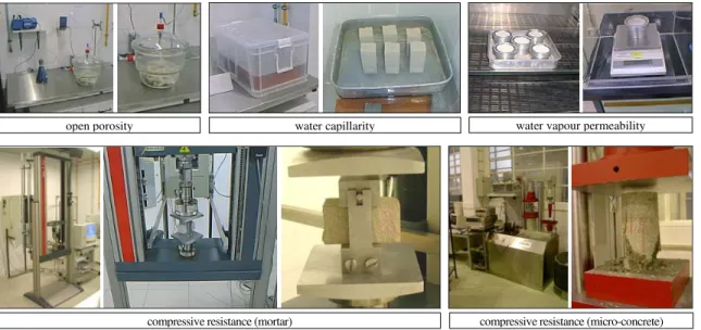
A large number of tests to find physical and mechanical characteristics of both wall construction and strengthening materials were done. Figure 5 shows pictures of five of those tests.
The mortar samples used in these tests have the following geometrical characteristics: for open porosity tests, small remainder parts of 160x40x40 (mm) samples (obtained after mechanical tests); for capillarity and mechanical tests, half of 160x40x40 (mm) moulded samples and for permeability tests, models with
φxh=950x10 (mm).
Figure 5 – Experimental tests to determine some physical (porosity, capillarity and permeability coefficients) and mechanical characteristics (stress-strain relationship and E modulus) of both masonry mortar and shotcrete
The following results, related to masonry and micro-concrete layers, will be referred: (i) open porosity, capillarity and permeability coefficients, as physical characteristics and compressive resistance and elasticity secant modulus as mechanical properties.
Table 1 present the experimental results of the referred tests (including bulk density). Nevertheless it should be referred that strengthening solutions were applied in two different periods: first samples, when the first layer was applied, and second samples, corresponding to the second layer. Between these two shotcrete layers, a steel mesh was applied, making part of the global strengthening solution.
The results presented in table 1 consider the obtained mean values.
Table 1 – Physical and mechanical characteristics of some wall construction and strengthening materials applied on the experimental masonry models
Physical characteristics Mechanical characteristics
Material Bulk density
[kg/m3]
Open porosity
[%]
Capillarity coefficient [kg/m2.h1/2]
Permeability coefficients
[kg/m.s.Pa]
Compressive resistance
[MPa]
Elasticity modulus [MPa] URM
(mortar) 1742,9 32,7 15,4 18,61×10
-12 0,58 63
Solution II
(micro-concrete) 2132,3 18,8 2,4 4,08×10
-12 36,0 27900
Solution III
(micro-concrete) 2232,3 15,8 1,5 3,27×10
-12 51,1 34200
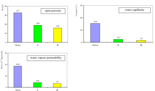
Figure 5 shows graphics with these values, in terms of the mean values, where the comparison of the results can better be done.
open porosity water capillarity water vapour permeability
32,7 18,8 15,8 0 10 20 30 40
Mortar II III
Pa [ % ] 15,4 2,4 1,5 0 10 20 30
Mortar II III
CC ap [kg/ m 2.h 1/ 2] 18,61 4,08 3,27 0 10 20 30
Mortar II III
PVA x
1
0
-1
2 [k
g/
m
.s
.Pa
]
Figure 5 – Comparison between several physical characteristics of both mortar (masonry) and shotcrete (strengthening solutions) used on the experimental models
These results show the higher velocity of water capillarity absorption of the mortar, comparing to shotcrete, due to a less dense internal structure of the mortar. Permeability coefficients of strengthening solutions should only be considered qualitatively according to the small number of tested samples. However, they show that shotcrete delays the evaporation of the water, comparing to the masonry.
The results presented in figure 6 (not included in table 1) complement the ones referred in figure 5, namely the capillarity tests, because they show a lower velocity of water absorption (in this case rain water). The problem is that shotcrete layers have also a minor permeability coefficient, meaning that water stays longer inside the masonry when those layers are present.
0,0 1,0 2,0 3,0 4,0
0 30 60 90
Time [min]
[c
m
3]
Mortar (90 days) II (158 days)
Figure 6 – Results of water absorption under slow pressure tests developed on URM models (mortar joins) and on a shotcrete layer (of strengthening solution II)
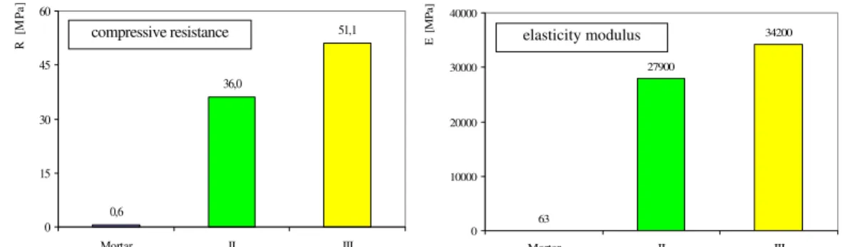
In Figure 7 two mechanical characteristics of some construction and strengthening materials applied on the experimental models are presented. These results show a big difference between the compressive resistance and the elasticity modulus of the masonry mortar and the shotcrete applied on the experimental models. In fact, such results were expectable and suggest that some cautious are necessary when these kinds of materials are putting together, like the use of mechanical connections (bars) between the layers applied on both faces of the walls.
open porosity water capillarity
0,6 36,0 51,1 0 15 30 45 60
Mortar II III
R [M Pa ] 34200 27900 63 0 10000 20000 30000 40000
Mortar II III
E
[M
Pa
]
Figure 7 – Comparison between compressive resistance and elasticity moduls of masonry mortar and shotcrete applied on the experimental models (II and III specimens)
As referred at the beginning of this paper, this type of strengthening solutions (based on shotcrete or concrete reinforced layers) are very common in Portugal, meaning they are very important on the mechanical resistance point of view. The research carried out on FCT/UNL (Pinho, 2007) tried to determine how strong these solutions are and has shown that, if the referred mechanical connections are well done, these strengthening solutions are efficient.
The other paper presented to this Seminar related with the research carried out shows as well that the difference between the strengths of the sample and the masonry models is not as large as the results presented in figure 6 suggest.
Regarding to the elasticity modulus, presented in figure 7, the results also show huge differences between stiffness of both materials mortar and shotcrete. This may represent a different mechanical behaviour of these materials during an earthquake or differential settlement foundations, for example. Once more, the use of mechanical connections (bars) between the concrete layers through the masonry is required to minimize this difference of stiffness The obtained elasticity modulus of shotcrete layers is quite similar to the mentioned at REBAP (1985).
Shotcrete samples, obtained by cutting cores from large cubes, have performed quite approximately the used matter, even though the optimal situation correspond to the cut of the shotcrete layers applied on the models.
3. MAIN CONCLUSIONS
According to the huge importance of reinforced micro-concrete layers as strengthening solution used in the rehabilitation of ancient rubble stone masonry, the durability aspects related in this paper should be considered, in order to guarantee a better performance of this strengthening solution. In this context, the type of cement or measures to difficult the contact between water and shotcrete layers and the water access to the wall must be considered, seeing that some chemical reactions only can happen in the presence of the water. In another way, the protection of steel mesh should be considered, in order to minimize the carbonation and the chloride effects. Steel mesh should have an adequate anti-corrosive protection and the shotcrete cover reinforcement should respect the applicable normalization (CEN, 2004; IPQ, 2004; LNEC, 2005). Therefore, the thickness of the layer is conditioned by the minimum steel cover value defined in such normalization.
The experimental results show that the water vapour permeability coefficient of the shotcrete layers is only about 20% of the one of the mortar masonry and the open porosity of the shotcrete layers is just 64% of the one of the mortar (figure 5). These results mean that the water stays longer inside the masonry when shotcrete layers are used as strengthening solution of rubble stone masonry, reducing the thermal insulation conditions of the external walls (decreasing the habitability conditions) and moreover contributing for degradation of the wall and even of the shotcrete layers.
The shotcrete capillarity coefficient is 13% of the mortar’s value. This means that the shotcrete absorbs less water per time unit than the lime mortar. However, a lower vapour permeability coefficient of the shotcrete layers comparing to the lime mortar, reduces the capacity of the strengthening solution in terms of water vapour evaporation present both in shotcrete and masonry.
It is also very important to notice that the comparison has been made in terms of the shotcrete material used for the strengthening solutions and the masonry mortar of the walls. In reality, the URM walls surfaces are protected by renderings, which were not considered here. So, it can be admitted that if the walls were rendered with lime based mortars, compatible with the masonry (Pinho et al, 2008), by means of its application (and necessary recompactation over the wall, after the initial shrinkage development), the resultant mortars would be denser than the analysed masonry mortar and their characteristics would be a little different; but if the URM walls were rendered by cement based mortars, all the problems caused by a low vapour permeability should also be present.
It seems that the major durability problems of the rubble stone masonry strengthened with shotcrete layers are associated with water migration. Important measures should be implemented in order to reduce the water access from the ground, by capillarity. The substitution of mechanically strong and denser shotcrete by a more vapour permeable material seems more appropriate (Pinho et al, 2008).
4. ACKNOWLEDGMENTS
This research was developed in the Structural Laboratory of DEC-FCT/UNL, and the first author was supported by a scholarship through the Program 2/5.3/PRODEP/2002.
The authors are grateful to the following twenty-three industrial companies, which sponsored the majority of the experimental work: Grupo Edifer; Secil Outão, SA; Secil Martingança, Lda; Lusical, SA; Tecnasol-FGE, SA; Betopal, SA; Tecnima-Enerpac; Betão LIZ, SA; SPGO Lda; Cimianto, SA; Lusoceram, SA; Construtora do Infantado, Lda; Ensul, SA; SIKA Portugal, SA; Degussa - Bettor MBT, SA; Codimetal, SA; Vimaplás, Lda; Fradical, Lda; Dywidag, SA; Parapedra, Lda; Somator, Lda; J. Piteira, Lda; F. F. Caçador, Lda.
5. REFERENCES
Appleton, J. (1991) Edifícios Antigos. Contribuição para o Estudo do seu Comportamento e das Acções de Reabilitação a
Empreender. Programa de investigação apresentado a concurso para provimento na categoria de investigador-coordenador.
LNEC. Lisboa.
Appleton, J. (2003) Reabilitação de Edifícios Antigos – Patologias e Tecnologias de Intervenção. Edições Orion, Lisboa. Coleman, R. (2000) Distribuição da Humidade e dos Sais Solúveis nas Alvenarias. Website: http://www.prorestauro.com
COMITÉ EUROPÉEN DE NORMALISATION (CEN, 2004) Eurocode 2: Design of Concrete Structures. Part 1-1: General
Rules and Rules for Buildings. EN1992.1.1. CEN, December, 2004.
Coutinho, A. S. (1997) Fabrico e Propriedades do Betão. Volume I. LNEC, Lisboa. Coutinho, J. S. (2001) Durabilidade. Ataque por Sulfatos. FEUP, Porto.
Decreto Lei Nº 349-C/83, de 30 de Julho de 1983 - Regulamento de Estruturas de Betão Armado e Pré-Esforçado (REBAP).
Imprensa Nacional Casa da Moeda. Lisboa, 1985.
LABORATÓRIO NACIONAL DE ENGENHARIA CIVIL (LNEC, 2004) Metodologias para Prevenir Reacções
Expansivas Internas. Especificação E461. LNEC.
LNEC (2005) Metodologia Prescritiva para a Vida Útil de Projecto de 50 Anos Face às Acções Ambientais. Especificação E464. LNEC.
Gonçalves, A. (2000) Exigências Relacionadas com a Durabilidade do Betão. Associação Técnica da Industria do Cimento, Magazine ATIC, 25, Lisboa.
INSTITUTO PORTUGUÊS DA QUALIDADE (IPQ, 2001) Cimento. Parte 1: Composição, Especificações e Critérios de
Conformidade para Cimentos correntes. NP EN 197-1. IPQ, Lisboa.
IPQ (2004) Betão. Parte 1: Especificação, Desempenho, Produção e Conformidade. NP EN 206-1. IPQ, Lisboa.
Nero, J.; Appleton, J. and Gomes, A. (1994) As Argamassas Tradicionais no Parque Edificado de Lisboa: Uma Colaboração
para o seu Conhecimento. 2º Encontro sobre conservação e reabilitação de edifícios. LNEC, Lisboa.
Pinho, F. (2000) Paredes de Edifícios Antigos em Portugal. Colecção Edifícios, Nº 8. LNEC, Lisboa.
Pinho, F.; Baião, M. and Lúcio, V. (2004) Estudo Experimental sobre Técnicas de Consolidação de Paredes de Alvenaria de
Pedra Ordinária. 2º Congresso Nacional da Construção 2004. FEUP, Porto.
Pinho, F.; Baião, M. and Lúcio, V. (2008) Experimental analysis of rubble stone masonry walls strengthened with reinforced
lime and cement mortar rendering and transversal ties. Challenges for Civil Construction. FEUP, Porto.
Faria-Rodrigues, M. P. (2004) Argamassas de Revestimento para Alvenarias Antigas. Contribuição para o Estudo da Influência
dos Ligantes. PhD Thesis. Engenharia Civil – Reabilitação do Património Edificado. UNL/FCT, Lisboa.
Silva, J. (1983) Medidas Destinadas a Evitar o Acesso da Humidade do Terreno às Paredes dos Edifícios. CPP 510. LNEC, Lisboa.
Valluzzi, M.; Porto, F. and Modena, C. (2001) Behaviour of Multi-leaf Stone Masonry Walls Strengthened by Different
Intervention Techniques. Historical Constructions, Guimarães.
Veiga, M. et al (2001) Metodologias para a Caracterização e Conservação de Argamassas de Revestimento de Edifícios
Antigos. Relatório Final do Projecto Oldrenders, co-financiado pela Agência de Inovação. LNEC, Lisboa.