Faculdade de Ciências e Tecnologia
Departamento de Informática
Dissertação de Mestrado
Model Driven Development Implementation of a Control
Systems User Interfaces Specification Tool
Orientador:
Prof. Doutor Vasco Amaral
Disertação apresentada na Faculdade de Ciências e
Tec-nologia da Universidade Nova de Lisboa para obtenção do
grau de Mestre em Engenharia Informática.
Lisboa
Para resolver o crescente problema de incremento de compexidade dos sistemas de software (devido à complexidade do dominio do problema, complexidade do domínio da solução e a
propria complexidade dos requisitos não funcionais), a comunidade de engenharia de software está a voltar-se para abordagens de Engenharia Orientada ao Modelo, onde as Linguagens de
Domínio Especifico(DSL) e Ferramentas de Transformação, são aspectos essênciais.
É neste contexto que surge o projecto BATIC3S, com o fim de a partir de uma DSL de
especificação, e por uso de níveis intermédios do seu mapeamento até à plataforma alvo, pro-totipar automaticamente Interfaces Gráficas para Sistemas de Controlo Complexos.
Havendo um desenho de DSL chamada (H)ALL já proposto para este fim, esta tese irá demonstrar uma implementação que garanta ao nível sintáctico, modelos bem formados, e ao
nível semântico, que o processo de transformação não introduz falhas no modelo de destino. Para chegar a este fim, vão-se usar ferramentas de meta-modelação de linguagens e
delinear-se regras de transformação de modelos, obedecendo a uma metodologia de transformação por níveis que demonstramos ser correcto.
Palavras-chave: Transformação de Modelos, Meta-modelação, Linguagens de Domínio
Es-pecifico, Engenharia Orientada ao Modelo, Interfaces Graficas para Sistemas de Controlo Com-plexos
To solve the growing problem of increasing complexity of software systems( due to the prob-lem’s domain complexity, the solution’s domain complexity and the non functional
require-ments complexity), the software engineering community is turning to Model Driven Develop-ment approaches, where Domain Specific Languages(DSL) and Model Transformation tools
are essential aspects.
It is in this context that the BATIC3S project is running, with the goal of automatically
create Complex Control Systems Graphical User Interfaces, from specifications made with a DSL built for this purpose, and with the use of intermediate levels of mapping to deliver it to
the target platform.
Existing a DSL design, named (H)ALL, already proposed for this purpose, this thesis will
demonstrate an implementation, that guaranties at the syntactic level, the well-formedness of the created models, and at the semantic level, that the transformation process does not introduce
faults into the target model.
To achieve this, a language Meta-modeling tool will be used, and a set of Model
Trans-formation Rules will be designed, according to a layered transTrans-formation methodology, which correctness we also demonstrate.
Keywords: Model Transformation, Meta-modeling, Domain Specific Languages, Complex
Control Systems Graphic User Interfaces, Model Driven Engineering
1 Introduction 1
1.1 Context 1
1.2 Motivations 3
1.3 Proposed Solution 4
1.4 Document Structure 5
2 State of the Art 7
2.1 Model Driven Development 7
2.1.1 Meta-modeling 8
2.1.2 Domain Specific Languages 9
2.1.3 Model Transformation 10
2.1.3.1 Graph Transformation 11
2.2 Control Systems 12
2.3 BATIC3S 12
2.3.1 (Human) Assisted Logic Language 14
2.3.2 CO-OPN 14
3 Tools 17
3.1 Meta-Modeling Tools 17
3.1.1 Meta-Modeling Tools Decision Criteria 18
3.1.2 Meta-Modeling Tool Analysis 18
3.2 Transformation Tools and Processes 20
3.2.1 Transformation Tools Decision Criteria 22
3.2.2 Transformation Process Selection 22
3.3 Summary 23
4 Correction of the Approach 25
4.1 Model Syntax Evaluation 25
4.1.1 Meta-Modeling Tools 25
4.1.2 Transformation Tools and Processes 26
4.2 Formalizing the Transformation 26
4.2.1 Formalisation attempts over model transformation rules 27
4.2.2 Partial order isolation of the transformation rules 27
4.2.3 Auxiliary Diagrammatic Formalism 28
4.2.4 Base Formalization Concepts 31
4.2.5 Rule Formalization 35
4.2.5.1 Left Hand Side: 35
4.2.5.2 Right Hand Side: 36
4.2.6 Rule Composition 36
4.2.7 Algorithmic Application of the Formalized Rules 38
4.2.8 Incremental Layer Specification 39
4.2.9 Semantic preservation 41
4.2.10 Confluence 42
4.2.11 Completeness 43
5 (H)ALL Language Engineering 45
5.1 Syntax 45
5.1.1 Meta-Modeling Process 46
5.1.2 Editor Generation 48
5.1.2.1 Creating the Domain Generator model 49
5.1.2.2 Creating the Graphical Definition Model 51
5.1.2.3 Creating the Tooling Definition Model 51
5.1.2.4 Creating the Mapping Model 51
5.1.3 Language Reprocessing 52
5.2 Semantics 52
5.2.1 Transformation Rules 54
5.2.2 Rule organization 58
6 Validation 59
6.1 First Set of tests 59
6.2 Case Study 60
6.2.1 ATLAS 61
6.2.2 Procedure 62
6.2.3 Results 65
7 Conclusion and Future Work 69
7.1 Conclusions 69
7.2 Future Work 70
A (H)ALL Metamodel Diagrams 71
B CO-OPN Metamodel Diagrams 83
C Editor Dependencies 89
C.1 Root Editor 90
C.1.1 Hall.gmfgen file variables 90
C.1.2 Hall.gmfmap file variables 91
C.2 UserProfile Editor 92
C.2.1 UserProfile.gmfgen file variables 92
C.2.2 UserProfile.genmodel file variables 93
C.2.3 UserProfile.gmfmap file variables 93
D ATL File Listing 95
D.2 Declarative02.atl 98
D.3 Declarative03.atl 100
D.4 FSM01.atl 102
D.5 FSM02.atl 107
D.6 FSM03.atl 109
D.7 mfsm00.atl 111
D.8 mfsm01.atl 113
D.9 mfsm02.atl 118
D.10 mfsm03.atl 121
D.11 Data01.atl 123
D.12 Data02.atl 126
D.13 Data03.atl 130
D.14 Data04.atl 132
D.15 Data05.atl 135
D.16 Router01.atl 138
D.17 Router02.atl 143
D.18 Router03.atl 146
D.19 Router04.atl 153
D.20 Router05.atl 160
D.21 Router06.atl 164
D.22 Router07.atl 168
E XMI models used in testing 173
E.1 First Phase Test (H)ALL Source Model 174
E.2 Example of CO-OPN output 175
1.1 Context of the presented work in terms of development flow 2
1.2 Problematics found in the 3
2.1 Model Driven Engineering layers within the context of domain language
engi-neering 8
2.2 DSL development steps 9
2.3 Relation between transformation elements 11
2.4 BATIC3S methodology with highlighted thesis context 13
2.5 CO-OPN diagram view example of a money box module 16
3.1 Transformation languages feature model 21
4.1 Rule scope representation 28
4.2 Left hand source model instance 29
4.3 Right hand source model instance 29
4.4 Right hand source model instance set 29
4.5 Target model instance 30
4.6 Right hand instance and non-terminal symbol relation 30
4.7 Non-terminal symbol propagation to target instance 30
4.8 Non-terminal symbol propagation to source instance 31
4.9 Implicit instance and rule relation 31
4.10 Left and right side relation 32
4.11 Meta-model for the diagrammatic view of the transformations 33
4.12 Composed diagram of a rule 34
4.13 An ATL rule sample decorated with the defined verticesV(_
,_,_) and function f_ symbols, produced by the symbolic interpretation of the rulesys2ctxuse. 38
4.14 Layer chain 39
4.15 Incremental model approach 40
5.1 Root meta-model 46
5.2 Component inheritance meta-model 47
5.3 Component meta-model 48
5.4 PreConditionExpression meta-model 49
5.5 Inter editor dependencies 50
5.6 GMF Dashboard 51
5.7 (H)ALL editor interface 53
5.8 ATL rule example 55
5.9 ATL propagation rule 56
5.10 example of an ATL rule that requires the use of layers 57
6.1 general purpose User Interface for the Online Software of ATLAS 61
6.2 Specification of the Visual Components of a user’s GUI 62
6.3 DAQ system and structure specification 63
6.4 FSM for component control 64
6.5 TreePanel XMI (H)ALL representation 65
6.6 TreePanel target context representation at layer Declarative02 65
6.7 TreePanel target data representation at layer Data01 66
6.8 TreePanel target context representation update at layer Data02 66
6.9 TreePanel target router construction at layer Router01 67
A.1 (H)ALL Meta-Model 73
A.2 Upper left section of the (H)ALL Meta-Model 74
A.3 Upper middle left section of the (H)ALL Meta-Model 75
A.4 Upper middle right section of the (H)ALL Meta-Model 76
A.5 Upper right section of the (H)ALL Meta-Model 77
A.7 Lower middle left section of the (H)ALL Meta-Model 79 A.8 Lower middle right section of the (H)ALL Meta-Model 80
A.9 Lower right section of the (H)ALL Meta-Model 81
B.1 CO-OPN Meta-model 85
B.2 CO-OPN ADT Module Meta-module 86
B.3 CO-OPN Class Module Meta-module 87
3.1 Meta-modeling tools analysis 20
3.2 Transformation tool analysis 23
This thesis was made within the context of the Computer Science Master’s Degree program held at Falculdade de Ciencias e Tecnologia of Universidade Nova de Lisboa.
1.1
Context
Within modern software engineering methods it is hard to conciliate requirements with
speci-fication and implementation of particularly large projects. To deal with this, new approaches have been created to tackle this problem. Some of these methods include the Model Driven
De-velopment (MDD) approach, that makes use of Domain Specific Languages(DSL) specification and Model Transformation techniques.
Model Driven Development sees models as artifacts in process where the specification of
systems start at a more abstract layer and are transformed, in a automatic or semi-automatic manner, to more detailed specifications at a lower level of abstraction in a systematic way. The
need for specifying the referred models at the different abstraction layers in some language motivate newly designed DSLs. Additionally Model Transformation is needed in order to give
semantics to these models and carry them to new steps of the MDD approach. The major advan-tage of this structured approach is that the specification gap between design and implementation
can be overcome, and it becomes possible, if properly designed, to derive solutions from a spec-ification centered simply on the problem and not the solution space of the implementation.
The MDD approach can be used for the purpose of rapid prototyping with several different goals besides implementation. Simulation or Verification are also possible in a integrated way
depending on the problem to be solved.
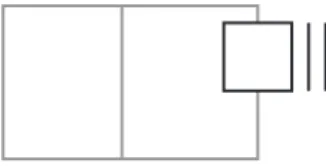
In it the elevated number of elements and critical responses, lead to a difficult conciliation of re-quirements with implementation, the former usually taking precedence. The BATIC3S Project1
was created to deal with these problematics. To do this an MDD approach was taken, as rep-resented in figure 1.1, by introducing abstractions over the domain with a Graphic User
Inter-face(GUI) specification language(in figure 1.1 referred as Domain Specific Modeling(DSM)), and carrying these specifications into a framework that introduced the abilities of producing
testing, verification and implementation code capable of integration with the controlled system and a GUI engine.
Model Transformation
Testing
Simulation
Implementation
DSM Framework Code SystemControl
Interaction
Figure 1.1 Context of the presented work in terms of development flow
1.2
Motivations
This thesis will focus in a particular portion of the BATIC3S project’s development, specifically the implementation of a high level abstraction visual language named (H)ALL2, in the form of
a diagrammatic editor, and then tackle the gap between the high level models created with the editor and the target platform CO-OPN3.
With the use of MDD methods, the need arises to show that the problem’s domain in focus is correctly specified and expressed by these methods, and that the computational solutions
provided do not suffer from the limitations, like error prone translations, caused by the semantic gap between the requirements specification in the models and their implementation when either
the manual or automatic approach is used. With this in mind, we want to ensure that the models are, at the syntactic level, well-formed and that, at semantic level, the translation process did
not introduce unwanted faults into the target models. Besides that we want to guarantee that the obtained model is syntactically correct according to the target language’s syntax, in our case the
CO-OPN language. The mentioned problems of each step are illustrated in figure 1.2.
user
Model Design Phase
Model
Transformation Phase
CO-OPN Model HALL model
where faults introduced during the
transformation?
are the models valid acording to the CO-OPN language? are the models valid at the HALL language syntax specification ?
Issues
Figure 1.2 Problematics found in the
To achieve this, we need to study processes that allow us to check these methods limitations.
And so, with this thesis we will implement the aforementioned language of the BATIC3S project 2presented in section 2.3.1
in a first phase and then verify, as explained, its integrity to find any flaws that may exist on the processes involved, producing correct results.
1.3
Proposed Solution
In [2] we have studies on the approach to control systems, its GUI specifications and
shortcom-ings. In the sequence of that study, it was created a language named (H)ALL, suited to tackle the observed shortcomings. From the initial specification, we move on to the implementation
of a editor, allowing us to further develop the language and eventually redesign it, due to its own shortcomings. One of the possible reasons for that redesign is that the proposed language
is visual and domain specific, which makes it highly dependent on its usability, and not only on the specification of concepts.
Having this in mind we establish the use of automated visual editor tools instead of building one from scratch. This enables a faster development of the editor, and a greater feedback to the
language development without compromising the already produced work. Besides that, the use of these tools, give us guaranties of the model’s syntactic correctness.
From the created visual editor,wehave the possibility of creating models that will be
trans-lated to the target platform. To achieve this, like for the editor creation process, we look into existing tools for model transformation, and search for the best suited for this task. After we
se-lect a tool that copes with the needs of this particular project, we proceed with the specification of the transformation rules, but first we design a transformation procedure , that enables us to
assume that after following it during the transformation rules design, the models produced by them are correct.
As the rules are created and we can generate partial models in the target platform, we test
them for syntactic correctness, and an observational verification of the semantic correctness of the transformation.
1.4
Document Structure
In this chapter, we introduced the context, motivations and a proposed solution to the presented problem.
In chapter 2, we present a series of preliminary concepts and related work, so that people
not familiar with the context of this thesis can better understand the context, the problem and the solution presented in this thesis.
In chapter 3, we describe related work, giving an insight to theevaluationmethods and tools
associated to the proposed solution. First, we analyze the elements associated with the meta-modeling of the high level elements of the solution and the editor implementation. Afterwards,
we evaluate tools and methods that allow the suppression of the gap between the design models and the target platform solution.
In chapter 4, we focus on the syntactic evaluation of the produced work and the properties and guaranties we can derive from this evaluation, and we analyze the semantic properties of our
solution and the way we can ensure that any semantic present at design time will stay unaffected throughout the proposed process.
In chapter 5, we begin to describe the process of engineering that lead to the creation of the
language editor and the transformation process that transfers the created models into the target framework. In this chapter we emphasise key aspects of development and implementation, as
to facilitate the recreation of the elements produced in this thesis.
In chapter 6, observational testing and case study is described, and the way this evaluation adds to the previous verifications of the solution.
In chapter 7, the conclusions of the developed work are presented. In it we describe the achieved goals and highlight the technological limitations. Finally we present the course of
future development and the way we can improve the achieved results.
To understand the proposed solution, we must take an understanding in a series of methods
and tools, which are presented in this chapter. We will start with general and move on to more specific, project centered concepts along the chapter.
2.1
Model Driven Development
Model Driven Development(MDD), also described in the literature as Model Drivel Engineering
(MDE) [11] [33], has its focus in the isolation of the problem’s context from its implementation aspects. To achieve this, a series of mechanisms are raised, to allow the representation of a
problem’s solution in a abstract manner, through the use of models. This type of abstraction can be achieved by using the problem’s domain own terms when defining the solution’s models.
Typically it is made use of Domain Specific Languages to capture the domain terms and their syntactic definition. All this allows that the domain expert can focus his efforts on th problem’s
solution, without any concern with details that do not contribute to the improvement of said so-lution, meaning how it is implemented in the solution domain(in programing steps). This type
of approach is visible in figure 2.1, where we can observe the relation between the several ab-straction layers and how this can create an abab-straction of the implementation process. It shows
the meta-meta-modeling layer( where we have the language used to specify other languages), the meta-model layer(where the description of the domain language rules is made) with an
ex-ample of a language specification meta-model, the modeling layer(where models are defined with the use of the specified DSL) with an example of a model instance, and finally its
im-plementation in code. Further advantages of this is the capability of developing solutions with multiple implementations(ex: multi-platform deployment) and any improvements on the
imple-mentation do not interfere with the solution and vice versa. We will now define this concepts in more detailed manner in the following subsection.
Figure 2.1 Model Driven Engineering layers within the context of domain language engineering
from [8]
2.1.1 Meta-modeling
In face of recent technologic developments, the definition of meta-model and its use, has
be-come vague and it spreads through development areas that go from computer sciences to indus-try. Still we can establish meta-modeling in the context of this thesis, as a rule definition and
abstraction mechanism, that allow the specification models and terms, from particular contexts. This facilitates the understanding of problems and helps coordinate partial solutions.
The concept of meta-modeling, is tied to the type of solutions being produced, imposing to
the created models, abstract characteristics relevant to the consistency of the produced solutions. So when we talk about meta-modeling in the context of DSL’s, we are dealing with the rules
2.1.2 Domain Specific Languages
The concept of Domain Specific Languages(DSL) is tied to that of abstraction. Through a
spec-ification paradigm, such as meta-modeling or language grammars, a set of domain concepts capable of expressing solutions for that domain are defined. This set of domain concepts allow
the abstraction of everything outside of the domain of development, such as specific implemen-tation details, focusing solutions on solving the problem.
GUI meta-model language meta-model
language editor
model
code/intermediate framework transformation development tool
rule extraction
development interface
syntax definition
semantics definition
domain
Figure 2.2 DSL development steps
As viewed in figure 2.2, the development process of a DSL, starts with the analysis of the target domain, and the collecting of abstract terms tied to that domain. These terms are
then expressed in a formal manner. For Visual DSL’s, this can be done with the help of a DSL specification tool. Most modern specification tools, use meta modeling paradigms such
as UML and entity relation diagrams, to specify visual languages, as a way to both connect to used enterprise procedures and because it simplifies the refactoring of the language as it is being
process with the user are defined. With the combination of these two sets of specifications, the language terms and the visual and interaction definitions, it is possible to produce an editor for
the created language. In most modern tools this step is produced automatically. With these steps we define the syntax of the DSL, this will allow the creation of models that can be used to
refine and verify the specification itself or to produce other forms of output such as execution code or documentation. The transformation of these models into other specifications, sets the
definition of semantics for the DSL terms.
2.1.3 Model Transformation
Model Transformation is the process by which models compliant to a set of rules, are turned into models compliant to a new set of rules[22, 21, 4]. In the context of this thesis these rules
are defined by means of meta-models. The transformation process itself is guided by a set of transformation rules that specify for the starting patterns what needs to be changed so that they
can cope to the target meta-model. The relation between the elements involved in this process can be observed in figure 2.3, where the source, target and transformation rules conform to their
respective meta-models, and all of these share a common meta-meta-modeling specification paradigm. This makes it possible to understand the terms used for each model and proceed with
the transformation accordingly.
This type of process can be as flexible and free as we want it to be. For this reason it becomes
necessary to ensure that when the transformation rules are created, they will produce the correct results. For this reason in this thesis we will approach this specific situation and study manners
to verify this process.
The concrete applications of model transformation are such as:
• Obtaining different “views” over the same model
ATL Meta Model
Meta Model
B Meta
Model A
Model B Model
A
Rules Meta Meta Model
conforms to conforms to
conforms to
conforms to
conforms to conforms to
Figure 2.3 Relation between transformation elements
not we obvious or wold take mush work(ex: balancing a tree data structure)
• Adapt a solution model to different frameworks, abstracting from the process the differ-ences of the different systems.
• To generate textual models, including automatic production of documentation.
• Application of model composition technics such as Model Weaving.
• Ultimately we can consider an execution step as a model transformation, were the source and target meta-models are the same, and its successive application leads to an
algorith-mic equivalent result.
2.1.3.1 Graph Transformation
Graph transformation[21, 7] is a very well studied field, and can be observed as a particular case of model transformations, were models conform to the abstract definition of graphs. This
target models. As such, it is essential to understand the concepts used in both graph description and graph transformation, so that one can observe the parallels created in the solution and
understand them.
We will describe transformation process in more detail in the following chapter, when de-scribing the correctness of our approach.
2.2
Control Systems
Control systems are systems composed by one or more control elements, whose objective is to
observe, manage and control other elements of a systems that can also be the control system itself. The type of system being monitored by a control system can be as varied as logic and
linear systems, with analog or digital elements, and deal with discrete or continuous events, or any combination of these situations.
The control systems focused in this thesis, can be classified as centralized reactive
sys-tems to observe and control critical, hierarchically structured syssys-tems, with an elevated number of elements.This means that usually extremely specific formation is necessary to operate and
maintain such systems.
2.3
BATIC3S
The BATIC3S(Building Adaptive Three-dimensional Interfaces for Critical Complex Control) project[30], was initiated in 2005, in a collaboration of Université de Genève(CH), Ecole d’Ingénieur
de Genève(CH) and Universidade Nova de Lisboa: Faculdade de Ciências e Tecnologia(PT). Its general goal is to create and develop methods and tools that allow for the rapid prototyping
scale complex control systems.
To achieve this, an MDD approach was taken for the definition and creation of the interfaces, where the overall process, is also managed with an abstraction philosophy over the remaining
aspects of implementation as shown in the BATIC3S methodology diagram in figure 2.4. In it we can observe, on the top semi-circle, the use of several abstractions over the specification of
a control system, such asuser profiles,system structure,system static behavior. These abstrac-tions are then combined into a single model. This combination is no longer under the control
of the domain expert that specifies the control system, and is made into the CO-OPN frame-work, as to allow intermediate verification of the models, production of simulation code, and
the generation of implementation code that will interact with the concrete system and a 3D GUI interaction engine.
For first steps of the definition of the graphic user interfaces, this was achieved within the project, by specifying a DSL for this purpose, as to define them in an abstract manner, and
with-out any reference to the concrete implementation. The connection of the abstract specification with the implementation section of the BATIC3S project is made through model
transforma-tion into the CO-OPN framework. These two steps are part of the subject of this thesis, and highlighted in figure 2.4.
2.3.1 (Human) Assisted Logic Language
The (Human) Assisted Logic Language((H)ALL), specified in [2] and [1], is a domain specific
visual language, that targets the specification and prototyping of large scale complex control systems graphic user interfaces. These objectives are achieved through a segmentation of
inter-face specifications into a hierarchic definition of components and users. These elements behav-ior is then defined through the use of finite state machines, where the triggering of transitions
and the values of states are defined with algebraic expressions. The purpose of this separation is to offer a more intuitive view of each aspect of the development of a controll system interface.
The interaction between the specified elements of the interface, is made through a system of message propagation across the hierarchy.
The original specification of (H)ALL, designs its semantics using a set of model
transforma-tion rules in Queries/Views/Transformatransforma-tions (QVT) [31]. Due to an absence of implementatransforma-tion of QVT, a new transformation process capable of setting the semantics of the (H)ALL models
has been studied and selected during the course of this thesis.
2.3.2 CO-OPN
The CO-OPN(Concurrent Object-Oriented Petri Nets)framework is based on algebraic
where all these aspects are encapsulated in a Object-oriented paradigm. The operational se-mantics present in CO-OPN, makes this framework open to rapid prototyping and simulation of
the models. A coordination layer confers expressiveness to model design, providing a form of representing distributed computation in an abstract way by representing the interaction between
the modeled entities. Furthermore, the framework’s syntax and semantics, allows the use of object-oriented heterogeneous concepts.
Model specification is made through a collection of ADT’s, classes and contexts in the OPN modules, and in a abstract and axiomatic form. This type of specification makes
CO-OPN effective as a model transformation target, of DSL models, because by using a modular construction, it allows the specification of the several components of a DSL, and their relations.
The development platform for the CO-OPN framework(CO-OPN builder [18]), allows the semi-automatic generation of code prototypes, execution and simulation of the prototypes, the
enriching of the prototypes with customized code, test application and prototype execution for validation[26]. CO-OPN builder also allows the generation of diagrammatic representation
of models, like that of figure 2.5, from their textual specification. In this diagram, we see an example of a model of a money box, with the use of places(circular elements inside the
money box module) to store values, gates to provide the interaction of the money box with other modules, and methods that connect these several elements, and order the flow of data
inside the module through the use of algebraic expressions.
In this chapter, we present an analysis of tools and methods used to model a domain language.
We will begin by looking at tools that allow for the specification of visual domain specific languages(with the use of some meta-modeling formalism), and the automatic creation of an
editor for those languages. From the models creatable by these editors, we will observe their expressiveness and compatibility with further steps of the development. These steps involve the
transformation of these models into models in the target framework, which confers semantics and allows to have a set of operational tool for testing, execution and simulation. To do this we
need to look at tools and methods that allow this transformation, and also allow the verification of the transformation process. From these observation, we will select the most suited to achieve
the proposed solution.
3.1
Meta-Modeling Tools
Although being possible to use other processes, such as graph grammars[], most recent
ap-proaches to visual domain specific languages, is done by specifying a meta-model of the created language. This approach means we specify the language through elements and connections
be-tween those elements. It also means that any combination of element connections is valid, and in some cases, this is not desired in the language specification. For these situations, restrictions
are added to the language specification, either through OCL expressions or through compilable code, and could be seen as a form of type checking(also called static semantics).
The referred approaches, allow for the automatic generation of visual editors, that can verify the syntax of the visual language at modeling time. This automatic procedure, facilitates both
the use and creation of such editors, through a more interactive process, therefore, they are suited for our requirements.
selection of the meta-modeling tool, we looked at [32]. From these we evaluated the presented tools and characteristics. From the information collected in this manner, and based on the
requirements of our solution, we established analysis criteria and candidate tools for meta-model and editor generation process. The final candidates were then evaluated for usability
through experimental use. In this way, we try to establish, an objective decision in our choice of the meta-modelling tools.
3.1.1 Meta-Modeling Tools Decision Criteria
So based on the existing evaluations and the requirements of our solution, we use the following criteria:
• can express all the expressivenessof (H)ALL, i.e. it is capable of representing all
syn-tactic requirements of the language, as to produce a correct metaphor of the domain.
• can express itsrestrictions, either by means of meta-model expressiveness or through the
use of additional specifications, like the use of OCL or compilable code.
• can generate a modeling interface that meets the expectations of the target modelers,
i.e. it will run in the development environment already used by the modelers, and that it possesses an interface that is intuitive or of rapid learning to those same modelers.
• Created models are suited to undergo thetransformation processinto the target
frame-work, i.e. that models are already in a standard format or that format can be expressed to the transformation language.
3.1.2 Meta-Modeling Tool Analysis
complete and integrated development process. So now we will proceed with a closer evaluation of these tools in the rest of this section.
GME has proven to be the easiest to use of the three, capable of expressing (H)ALL’s
re-quirements and restrictions, using meta-modeling process close to MOF. Nevertheless, the mod-els created by this tool although in XML, were based in an unpublished specification
discour-aging its use with other tools outside of the GME environment. The interface of the generated editor although limited, presented a good level of usability, providing customizable element
features, the separation of tools into tabs for better organization and providing command line interaction.
DSL Tools required the most adaptation of the original (H)ALL proposal to its own meta-model paradigm, which is not based on the MOF standard, unlike the other selected tools.
Additionally, no constraints expressiveness was provided by this tool at this point. The interface although being somewhat rigid, allows for the inclusion of customizable elements, and the
organization of a Toolbox. The models generated by DSL Tools are defined in a proprietary format of XML, discouraging its use outside the development tool’s environment.
GMF has its models defined in the eclipseecoreformat. This format is based on the MOF
standard, and is paired with a set of tools that allow its exchange with other formats. During the editor specification process, it is possible to add OCL and Java code constraints to its use, but
not directly into the meta-model. The interface, although hard to specify beyond the default, allows for its full customization. The models generated by this tool abide by the XMI standard,
allowing full integration with any tool that is compliant with this standard.
As a consequence of our analysis summarised in table 3.1 we chose GMF as our
meta-modeling tool to implement our solution. We chose it based on its capabilities of expression, standards use, evolution potential and capability to interact with other tools. Additionally other
Name DSL Tools MetaEdit+ GMF GME AtoM3
Expressiveness + + + +
-Standard Meta-Model Definition - - - ++ ++ +
Resulting Interface + - ++ +
-Restrictions Definition - N/A ++ + +
Cross Platform - + + - +
Table 3.1 Meta-modeling tools analysis
3.2
Transformation Tools and Processes
Although defined as a standard, to be added to the also standards MetaObject Facility(MOF)[14]
and Unified Modeling Language(UML)[17] specifications, by the Object Management Group(OMG)[16],
QVT[31] still has no tools that fully implement its use. Nevertheless from their efforts to build this standard, many transformation languages have risen with solutions that complement
it with alternative methods and specifications, such as VIATRA[6], while others tried to inte-grate some level of compatibility with QVT in themselves[13], such as the Atlas Transformation
language(ATL).
Not being possible to use QVT as our transformation language, we need to select tools and methods, that allows for the correct transformation of the created models into models of the
target platform and that allow for thevalidation and verification of this process. To do this, we started by looking into a survey [22] that clarifies the different model transformation aproaches.
We also looked at a survey to evaluate model transformation processes[21], such as graph trans-formation, triple graph transtrans-formation, relational algebras, XML to XML transformation by
evaluation of it’s text patterns and even mixed solutions, their features and tools that support them.
select the methods that are better suited for this particular transformation process. This bene-fits the selection with a greater control and understanding of the transformation process, also
essential to the verification of this step, by allowing us the association of the methods used in transformations, to formalisms that can help us to verify those transformation. Additionally we
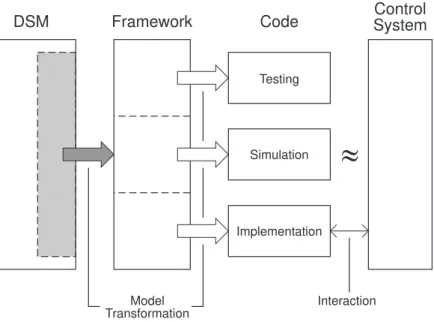
look at a set of features present in the evaluated transformation tools. These features, presented in figure 3.1(where black dots mean mandatory features and empty dots mean alternative), as
re-ferred to in [22],are such as, bi-directionality of the rules, if the transformation is typed, if there is a need to use intermediate structures or models for the correct execution of the
transforma-tion, if method application is deterministic, a full application is destructive to the source model and if it is possible to define or other sets to the rules as to ensure integrity and convergence of
solutions.
Figure 3.1 Transformation languages feature model
from [22]
From the analysis presented in [22] and [21], we are also shown that through compliance of graph transformation to the source and target meta-models, similar to that present in figure 2.3,
3.2.1 Transformation Tools Decision Criteria
So we establish our needs from a transformation process and language in the following manner:
• it has to allowa formalverification, ether by itself and its implementation, or by allowing
its comparison with known formalism.
• it has to be capable of detecting and generating the desired model patterns
• it has to ensure that created modelsconform totheirmeta-modelspecification
3.2.2 Transformation Process Selection
From this evaluation, as presented in table 3.2, Viatra2 and ATL were selected for a further
analysis. Testing the two languages for their concrete capabilities.
Viatra2 although promising in use of graph transformations, its use of state machines to control the transformation process, dictating the sequence of the transformation rules, and its
compatibility with the environment and models of the model generating editor, it did not achieve the usability necessary to implement our solution.
ATL showed to have a good level of expressiveness, allowing the declarative and impera-tive specification in the transformation rules. Furthermore, ATL allowed its comparison with
the graph transformation formalism, although not used for the transformation process itself. Integration with the chosen development, the Eclipse framework, support and standard status
ATL Viatra QVT GREAT
Visual Rule mapping - + - +
Multiple Meta-Models + + +
-Declarative Rules + +
XMI compatible + + N/A
-Usability ++ - N/A +
Syntactic Conformity + + +
Table 3.2 Transformation tool analysis
3.3
Summary
In this section, we have proceeded with a deep analysis, where the selection of the GMF/EMF
language workbench and the ATL transformation tool were justified. We have also observed that these type of tools are rapidly evolving. Although the Meta-Editor tools present some
lim-itations of expressiveness, they are benefiting from the paradigm they implement, allowing the adoption of MDD methods in developing the tools themselves. This allows for a rapid
develop-ment cycle, that unfolds in their rapid evolution allowing for better expressiveness, usability and stability. Knowing this, we are aware that the chosen tool for this task will be outdated in a near
future, but most of the core procedure will be maintained. Besides that, these tools facilitate the edition and generation process, becoming easier to update and maintain our developments.
As for the transformation languages, many are being added visual editors, although not yet us-able with ATL at the time of our thesis, allowing the representation of rules and patterns at the
same level as the model creation. The transformation processes are also evolving in terms of efficiency, becoming faster and more reliable, and also in terms of expressiveness, allowing for
the description of more complex transformation patterns.
In this chapter, we study the approach and methods used to implement the (H)ALL language
and deliver it to the CO-OPN framework.
This study is made in two phases. In the first phase, we study the syntactic properties and guaranties given, by the meta-modeling tools, in order to understand if they are already being
properly covered. In a second phase, we propose a set of properly formalized procedure, that ensure the semantic correctness of the transformation rules.
4.1
Model Syntax Evaluation
To guaranty the soundness of the development process, and that no errors are introduced in the
models, we must first evaluate the syntactic guaranties of the tools used. First we observe the Meta-modeling tools to ensure that the user describes a well-formed initial model. Following
that, we evaluate the transformation process itself for the maintenance of that well-formedness.
4.1.1 Meta-Modeling Tools
While editing models in GMF, these are maintained in conformity the their specification
meta-model, as the editor, does not allow the creation of patterns not present in meta-model. The syntax of the models can be further restricted with the use of constraint rules.
Although useful in the current implementation of the (H)ALL meta-model, for detection
of possible circular referencing in the hierarchy constructions, these suggested rules where not created. This occurred, because the particular rules necessary, implied the use of non standard
OCL[15] rules, or the inclusion of non generated Java code into the editor, and this wold fall outside the objectives of this thesis.
of the fault patterns in the transformation process. But this implied the design of an error detection meta-model, and it compromised the termination guaranties, present in the application
of layered rules.
Furthermore, these limitations of the current version of (H)ALL, are not assured in new
implementations of (H)ALL, as the language and its interaction are still evolving.
For these reasons, and the still restricted use of the (H)ALL editor, we can assume the
syntactic correctness of the (H)ALL models.
4.1.2 Transformation Tools and Processes
With the study of model transformations we observe that there is a conformity relation between models and their respective meta-models. So rules set to patterns present in those meta-models,
produce compliant models, if the source models are themselves compliant to their respective meta-models. This is shown in [21], and illustrated in figure 2.3. If such compliance is not met
the transformation tools are not capable of recognizing the rule application patterns, invalidating the full transformation process.
Taking this in consideration we can assure that, the given well formed (H)ALL models will produce syntactically correct CO-OPN models.
4.2
Formalizing the Transformation
As there is no formal description of the ATL, one is described in this section, in the form of rule application used in our particular transformation process.
We only evaluate a small part of the ATL language, otherwise it would fall beyond the scope of our objectives, and a very time consuming task to fit in our master thesis scheduling. Working
4.2.1 Formalisation attempts over model transformation rules
There have been some research in the formalisation of both model transformation rules and its
validation properties. However, we question the level of abstraction of these formalisations, since they typically do not give us (in general) enough rationale in order to be able to decide
about the satisfaction of some validation properties in a particular set of model transformation rules, in a systematic way.
In the work of [25], it was presented a clear separation from a specification of a model trans-formation and its implementation. A formal language for the specification of model
transfor-mations (MTSpecL) is presented to allow a pure specification of model transfortransfor-mations with the notion of contracts, and regardless of its implementation. However, in this particular case,
this formalisation is applied to the problem of generating test cases for model transformations expressed in several kinds of transformation languages (ATL, etc.). Furthermore, this definition
seems to be closer to the model transformation designer, in terms of usability and prototyping, instead of achieving a clear rationale to perform verification and validation over the
transforma-tion rules.
In [34], it was presented a definition of the property of metamodel coverage, which includes
feature, inheritance, association and model elements. Furthermore, it was presented algorithms to measure the metamodel coverage over the defined transformation rules, which is an important
step to perform verification over transformation rules. In this work, they have chosen to exper-iment the Tefkat transformation language, but they did not present any kind of formalisation
over this language.
4.2.2 Partial order isolation of the transformation rules
There also have been several studies which indicate a significant effort in the partial order
in the life cycle of model transformation designs. Also, it was presented some important guide-lines and properties that need to be checked during the validation of some model transformation
design like:
• Syntactic correctness of both input and output models.
• Termination and confluence (unique results and determinism).
• Semantic equivalence or semantics preservation.
• Safety or liveness (to ensure preservation of structural or security properties).
4.2.3 Auxiliary Diagrammatic Formalism
First we derive the rules in a schematic form, with the main characteristics needed to help us evaluate the scope and repercussions of each rule application, and to define the ATL declarative
sub-set we will be evaluating.
For the characteristics evaluated in the schematic diagrams, we create the following
sym-bolic representation. Rule scope is presented as in figure 4.1. Source and target model instanti-ation , represented by and respectively. Non terminal symbols, represented by . And
propagation is made explicit with . This last encompasses instantiation of non terminal symbols, rule relation and left and right element relations.
Lhs Rhs
Figure 4.1 Rule scope representation
The rule scope is characterised by a right hand side corresponding to the frompart of the
ATL rule, and a right hand side corresponding to thetopart of the ATL code. Furthermore left
on the right hand side, but regardless of declaration order. In our use of ATL the declaration’s scope is limited to the declaring rule itself.
Figure 4.2 Left hand source model instance
Figure 4.3 Right hand source model instance
Figure 4.4 Right hand source model instance set
The source model instances can be represented on the left side of a rule scope(figure 4.2), making them as part of the rule’s application pattern, or on the right side of the rule. When it
appears on the right side(figure 4.3 and 4.4), it always represents a potential instantiation that relates to another rule application, and can be a single application( ) or a set( ). In the ATL
code this appears as an implicit declaration through a relation or directly referencing an element of the source model. This potential state is made explicit in the schematic form by placing the
instance in the rule’s right outer boundary.
Target model instances only appear on the right hand side of the rule scope(figure 4.5), and
Figure 4.5 Target model instance
other instances. This close relation between the target instances and non-terminal symbols is represented placing the non terminal symbol directly below the related instance(figure 4.6).
Figure 4.6 Right hand instance and non-terminal symbol relation
The non-terminal symbols can then propagate the rule to other terminal target model
sym-bols, creating a chain of instantiations within a rule(figure 4.7), or propagate to a source model reference(figure 4.8), postponing the propagation to another rule.
Figure 4.7 Non-terminal symbol propagation to target instance
The propagation, although viewed with a unique arrow symbol, it conveys three different
meanings, but all of them contributing to the rule application in sequence. The non terminal symbol reference to an instantiation(figures 4.7 and 4.8), for every time a non terminal symbol
is raised, an instantiation, be it implicit or explicit, must be associated to it. A parallel be-tween implicit instances and the rule that will explicit that instance(figure 4.9). And the internal
association between the left hand side pattern elements and the right hand side(figure 4.10).
Figure 4.8 Non-terminal symbol propagation to source instance
Figure 4.9 Implicit instance and rule relation
4.2.4 Base Formalization Concepts
With the rule analysis aid specified, we now set the basic concepts in the formalization process. For this we can look at a model as a set of vertices and edges in a directed graph description
of the model. But, as this is a representation of a DSL model, just the vertices and edges are not enough. These items, must also be labeled to distinguish their properties as domain specific
elements.
Also as we make the transformation process through ATL, the origin models and the target models are strictly separated. This separation is represented as Left hand side and Right hand
side models. Where we only read from the Left hand side, and only wright on the Right hand side.
Because of this strict separation and rule sequence needs, we chose to layer the set of
trans-formation rules, making it possible to read the output model of a given layer as an input of any subsequent layer, usually the next layer.
Having the notion of vertices, edges, labeling, left hand side, right hand side and layers, we begin do describe the formalization as such.
LetΣV L andΣELbe the finite alphabets that label the vertices and edges of the left hand side
Figure 4.10 Left and right side relation
side vertices, whereVL∩VR= /0. In the same manner the sets of edges areEL for the left hand
side edges andER for the right hand side edges. Where EL is composed of left hand vertices and edge labels in the formEL ⊆VL×ΣEL×VL andERis composed of right hand vertices and
edge labels in the formER⊆VR×ΣER×VR. Finally letlL:VL →ΣV L be a total function that associates left hand side vertices with left hand side vertex labels and lR :VR →ΣV R a total
function that associates right hand side vertices with right hand side vertex labels. The triples
gL(VL,EL,lL)
and
gR(VR,ER,lR)
are directed labeled graphs of the left hand model and the right hand model, overΣV L,ΣELand
ΣV R, ΣER respectively or just left hand graph and right hand graph. These notions are present for each individual layer, but because more concepts are needed for the correct definition of the
layering process, they will be presented later in this section.
We now add the notion of subgraph, where given two graphs giandgj,gi is a subgraph of
gj, in symbolsgi⊆gjiff
Vi⊆Vj,Ei⊆Ej,li=lj|Vi
We also add the notion of incident edges, wheregL incident tovL∈VL is
incgL(vL) ={(sL,elL,tL)∈EL|sL=vL∨tL=vL}.
If we considerWL⊆VLa non-empty subset ofVL, then
incgL(WL) = [
vL∈WL
Lhs
R ule
R hs
0..n 0..1
0..1
0..1 1..1
Layer
0..1Figure 4.11 Meta-model for the diagrammatic view of the transformations
Finally we add the notion of path where a direct path between two nodes is defined as the
existence of an arch that directly connect those two node, which can be formalised as: for a pair of nodes(A,B)there is a direct path path(A,B)if
inc(A)∩inc(B)6= /0
For a broader definition of path between A and B we take that if there is a path between A and
C and there is a path between C and B there is also a path between A and B. This can be written as
path(A,C)∧path(C,B)⇒path(A,B)
rule ruleN am e{ from
a.. src : SourceM M !sourceTypeLabel to
b.. trg : TargetM M !targetTypeLabel( Attribute <- src.sourceAttribute, c.. anotherAttribute <- extraElem ent, d.. yetAnotherAttribute <- anotherElem ent,
),
e.. extraElement : TargetM M !anotherTargetTypeLabel ( f.. extraAttribute <- src.sourceR elation
),
g.. anotherElement : TargetM M !yetAnotherTargetTypeLabel (
h.. Attribute <- src.anotherSourceR elation ) a b c d e f g h i j
Figure 4.12 Composed diagram of a rule
notions work similarly for both left hand graphs and right hand graphs.
In ATL, as in other transformation languages, we get a notion of matching the left hand side elements of the rule to the source model, as to transform it to the representation on the
right hand side. As source model and rule application conditions are describable as graphs, this notion of elements matching is formally described as a graph morphism, and represented in
the diagrammatic analysis as shown in figure 4.9. This morphism is represented in a injective vertex map function.
For the definition of this morphism, letgbe a graph,VL′ a vertex set andhV :VL →VL′ be a
total injective vertex map. The edge map induced byhV ishE((s,el,t)) = (hV(s),el,hV(t))for
(s,el,t)∈EL. The morphism ˆhbased onhV is defined by
ˆ
h(g) = (hV(VL),hE(EL),lL◦h
−1
V )
wherehV(VL) ={hV(v)|v∈VL}andhE(EL) ={hE(e)|e∈EL}.
If h is a bijection, then ˆh is a isomorphism, and g and ˆh(g) are isomorphic in symbols ˆ
h(g)∼=g.
4.2.5 Rule Formalization
The matching of LHS elements defines the domain application of the transformation rules.
These rules can be formalised as
Rulek= (LHSk,RHSk,fk)
where LHSk defines the preconditions of application of the rule k, RHSk defines the
post-conditions of the rulek, and the function fkrelates the LHS application to the RHS application. Due to the complexity of sets in further defining the components of a rule, the following
no-tation will be used: X(w
,z,k) where X is an element (it can be a vertex, an edge or a labelling function), w denotes the element’s position inside the rule (either left or right hand sides), z
denotes the element’s position on the symbolic propagation chain defined inside each rule and among them, andkdenotes the exact rule where the element is defined. The symbol ’_’ denotes
the available positions for allw,zandk.
4.2.5.1 Left Hand Side:
The LHS of a rule is defined as
LHSk= (V(l,p,k),l(l,_,k))
whereV(l
,p,k)⊆VSandl(l,_,k)=lL|V(l,_,k) define the set of elements where the rule is applicable. The labelling function here is used to label all LHS vertices, including vertices from the LHS
of the transformation rule which are referenced on the respective RHS of a rule. Furthermore, we partition thezgroup into three kinds of positions on the propagation chain: head vertex (p),
middle vertex (m) and target vertex (t). Note also that head elements are heads of the propaga-tion chain on each side of the rule, and by theLhsk definition, there can only be defined head
OCL rules, however the formalization of these rules are out of the scope of this paper - in [3] you can find an approach on the formalization of OCL rules in a theorem prover.
4.2.5.2 Right Hand Side:
In order to connect LHS head elements with RHS head elements, we define function fkwhich relates a head element of LHS of rulek(denoted asV(l
,p,k)) with a head element of RHS of rule k(denoted asV(r
,p,k)).
fk:V(l,p,k)→V(r,p,k)
ATL allows the connection of the rules to each other by means of an association of a non terminal symbol defined on the RHS of the rule with some terminal symbol from the input
model of another rule. The symbol references from the input model of another rule are usually expressed in ATL by using OCL constructs like ’allInstancesFrom’ which are then composed
with ’select’ and ’any’ constructs, to ensure the correct binding with the output of a determined rule.
To denote this notions, we have to define all the edges between vertices inVS which were re-ferred on the RHS of rule k, asE(l
,_,k)⊆(sl,ell,tl)∈EL directed to elements inVS, where the source vertex of the edges are defined assl∈V(l,p,k)and the target vertex astl ∈VS.
Since, in ATL, we can explicitly refer to a determinate input instance (instead of a relation
which usually covers sets), we also define vertices which represent elements in VS and were referred on the RHS of rule k, i.eV(l
,t,k)⊆VS, whereV(l,p,k)∩V(l,t,k)= /0.
4.2.6 Rule Composition
Finally the connection between rules is made clear with the definition of function g, which relates target elements of RHS of some rulek(denoted either asV(l
ortlif it belongs to an edge) with head elements of LHS declared in rule j(denoted asV(l,p,j)).
gv:V(l,t,k)→V(l,p,j)
ge:tl→V(l,p,j)
The propagation chain defined on the RHS of the rule is used to produce a graph on the RHS of the transformation rule set. After the execution of the rule, there was produced a set
of verticesV(r,_,k)⊆VR, and a set of edges which connects them: Er,_,k⊆(sr,elr,tr)∈ER. The sources of these edges are head and middle verticessr =V(r,p,k)∪V(r,m,k). The targets of these edges are middle verticesV(r,m,k), which represents explicit output terminals, plus the result of the interpretation of the implicit references to source model entitiesV(l
,t,k), plus the result of the interpretation of the implicit references to source model relationstl. The target of the edges are
then defined as
tr=V(r,m,k)∪fj◦gv(V(l,t,k))∪ fj◦ge(tl)
.
The interpretation of target elements in rulek, is done by means of application of the result of
functiong in function f, given that function gmatches target references with the appropriate rule, and function f matches source elements with target elements in the chosen rule.
Finally, the RHS of a rule is defined as
RHSk= (V(r,_,k),E(r,_,k),l(r,_,k),E(l,_,k),V(l,t,k))
where the RHS labelling functionl(r ,,k)
is defined asl(r
,_,k)=lR|V(r,,k) . In the figure 4.13, it is shown an example of an ATL rule, whereV(l
,t,sys2ctxuse) can also be seen asVSpreMbounded by some condition withtl. In the example this is expressed by the composition
module Layer02;
create coopnModel : COOPN refining hallModel : HALL, preM : COOPN;
rule sys2cxtuse { from
h : HALL!SystemComponent
(not h.componentSetInv.oclIsUndefined()) to
c : COOPN!ContextUse(
usedContext <- COOPN!COOPNContext.allInstancesFrom('preM') -> any( e |
e.name = 'SystemComponent' + h.name ) )
}
V(l,p,sys2ctxuse)
V(r,p,sys2ctxuse)
V(r,m,sys2ctxuse)
V(l,t,sys2ctxuse) fsys2ctxuse: V(l,p,sys2ctxuse) -> V(r,p,sys2ctxuse)
tl
Figure 4.13 An ATL rule sample decorated with the defined verticesV(_,_,_)and function f_ symbols,
produced by the symbolic interpretation of the rulesys2ctxuse.
4.2.7 Algorithmic Application of the Formalized Rules
Now that we have the ATL elements defined, we can study the transformation process, based on ATL’s default mode execution semantics description[19] and [9]. From this we take that
the application of a transformation is divided in three successive phases: a module initialization phase, a matching phase of the source model elements, and a target model elements initialization
phase.
• The first phase, initialization, Although not used in our particular study, ATL attributes
that are defined in the context of the ATL module and subsequent dependencies, are ini-tialized in this phase.
• In the next phase, matching of the source model elements, the source model patterns
declared in the left hand side of the rules scope, are tested for a match subgraph on the source models. For this we use the morphism function ˆh, allocating resources for
all isomorphisms detected. This allocation is composed by the target model instances declared for every matching rule, without any initialization.
present in the rules are resolved in this phase, referring only to the finite set of allocated elements, ensuring termination of the ATL run in the presence of circular references.
4.2.8 Incremental Layer Specification
We define the notion of layer by expressing it in terms of a graph grammar. Each layer runs only once by executing all of its transformation rules, using the input from the previous layer
and passes its output (and the remaining input) to be input of the next layer. Specifications are isolated at each layer. Each layer is a set of rules which deals each one with a disjoint set
of input symbols and the execution of these rules occurs in a non-deterministic fashion. The transformation rule application algorithm can be viewed as one single layer in operation. When
we have a sequence of different layers as shown in figure 4.14, the sets of rules in each layer are applied consecutively, where the output model of one layer (in addition to the original source
model), is given as input to the next layer, in the manner presented in figure 4.15. In this se-quence of layers, each one makes small (but visible) contribution to the overall transformation
process.
Transformation Layers
Source
Model
1
2
3
Figure 4.14 Layer chain
The formal definition of transformation layer is
Layerq:(gsq,Rq)→gtq,
wheregsq represents the input graph of the transformation layer,Rqis the set of rules that define
Intermediate
Models
Target
Model
Source
Model
1
3
2
Figure 4.15 Incremental model approach
Furthermore, we show that for the first layer, no common elements can be found between the
Source and Target models (this is given directly from the transformation rule definition).
V s0⊆VS
V s0∩V t0= /0
Also, the Source elements of the remaining layers will be composed by a mix of source
ele-ments and intermediate target eleele-ments, and the result of each transformation will only have intermediate target elements. A consequence of this is that if there are common elements in the
Source and Target models of a layer, those elements must be the result from the previous layers.
V sq∩V tq=V tq−1
The Source models of a layer can be composed of elements of both Source and Target elements
of the full transformation process
V sq⊆VS∪VT
However, the Target models of a layer can only be composed of elements of the Target elements
of the full transformation.
The first noteworthy quality given by the layer abstraction is that it makes it possible to design the set of layers in a incremental way, hence enhancing the validation/navigation capabilities
during the design process, where the model transformation designer is able to easily identify the layer (or sequence of layers) which is responsible for the consumption of a given input
sym-bol (just by identifying the layer which is not propagating that symsym-bol). The second noteworthy quality given by the layer abstraction, is that it can be used to effectively simplify the structure
of logical predicates which forms the properties that the designer might want to satisfy while validating a set of model transformation rules. This simplification is made available by means
of the definition of temporal partial order relations between transformation layers, where inside each layer there is no temporal relations of any kind between rules (i.e we cannot say which
will be the first rule to be applied).
4.2.9 Semantic preservation
In our context of the transformation of computational-based semantic models, one important
property that should be checked is the semantic preservation of the model transformation rules, i.e if there is a direct relation between entityAandBon the source language, provided thatAis
transformed toA′andBis transformed toB′, then there should also be a relation (it might not be a direct one) betweenA′andB′on the target language.
In general, to demonstrate these kinds of properties, we often need to isolate the temporal expressions from what is to be guaranteed at each layer. Once the temporal partial order relation
between transformations is discarded (as happens inside a transformation layer), we can focus our analysis in purely logical reasoning by evaluation of the paths found between the syntactic
structures present on each transformation rule. The above property can thus be rewritten to ’if there is a path between two elements in the input left hand graph, then there must also be a path
between their respective elements on the output right hand graph’.
them. This is written as: for a pair of nodes(A,B)there is a direct path path(A,B)if
inc(A)∩inc(B)6= /0
For a broader definition of path, betweenAandBwe take that if there is a direct path between
AandCand there is a direct path betweenCandB, then there exists is a path betweenAandB.
This is written as
path(A,C)∧path(C,B)⇒path(A,B)
Note that this notion decomposes any path as a composition of direct paths. This notion works similarly for both LHS graphs and RHS graphs.
To assure semantic preservation of the transformation process, we analyse both the paths on source and target models, and how these paths connect each other inside and among the defined
transformation rules. Therefore, we must assure that if there exists apath(A,B), whereA∧B∈
VS, then there must exist at least a rulek with A=V(l,p,k) and a rule j with B=V(l,p,j), and a association function g which relates either tl or V(l
,t,k) with V(l,p,j). This ensures that for every possible source model of the transformation rule, if there exists a directed path between
its vertices, then there also must be a directed path between the correspondent vertices on the generated target model.
4.2.10 Confluence
It is important to remember that the execution of the transformation rules is done in a non-deterministic fashion inside a layer. Therefore, in order to guarantee confluence i.e uniqueness
on the results of the model transformation, we have to impose new restrictions to the application of the transformation rules. IfK is the set of all rules present in each layer, then:
∀i∈K,V(l
,p,i)∩ {
[
j∈K\{i}
V(l
4.2.11 Completeness
To achieve completeness in the overall model transformation, i.e if all entities of the source language must be translated to entities on the target language1, then we must assure that for all
v∈VS, there must be at least a layer q with rulekwhich defines v asV(l,p,k):
∀v∈VS,∃Rulek∈Layerq:v∈V(l
,p,k)∧Lhsk(V(l,p,k),l(l,_,k))
1Note that in some cases in model transformations, we might want to ignore some useless entities or their

![Figure 2.1 Model Driven Engineering layers within the context of domain language engineering from [8]](https://thumb-eu.123doks.com/thumbv2/123dok_br/16516035.735227/24.892.239.658.212.542/figure-model-driven-engineering-layers-context-language-engineering.webp)


![Figure 3.1 Transformation languages feature model from [22]](https://thumb-eu.123doks.com/thumbv2/123dok_br/16516035.735227/37.892.148.755.602.854/figure-transformation-languages-feature-model-from.webp)