Effect of Pile Orientation on the Shear Strength of Stitched Foam Sandwich Panel
Ramraj Santhanakrishnana* , Narayanan Kavithaa, Meenakshi Sundarama,
Pappakudi Srinivasan Venkatanarayanana
Received: December 18, 2017; Revised: June 15, 2018; Accepted: August 05, 2018
Stitched foam sandwich panel is a newly developed sandwich structure used in various structural
applications. The sandwich skins are made of glass-fiber/epoxy-matrix composite; their interior layers are connected with glass yarn called piles. This paper investigates the effect of pile orientation on the
shear strength of stitched foam sandwich panel. Four types of pile orientation are used; 90º, 45º, 90
º/45 º and 90º/45º/90º.The results are compared with a non-stitched sandwich panel. From the results of the core shear test, it is observed that the panels with 90º/45º/90ºorientation proved to be strongest
among all.
Keywords: Glass yarn, Stitched foam sandwich panel, Pile orientation.
*e-mail: [email protected]
1. Introduction
One of the most important advantages of the sandwich
construction is high stiffness to weight ratio. The in-plane
properties of the face sheet can be greatly increased by
changing the orientation of the fiber direction, whereas out
of plane properties are dependent on the resin. If the resin absorption is not uniform between the layers of the face sheets there is a possibility of delamination in between the layers. One of the methods to improve the out of plane properties of the face sheets is stitched through its thickness as given by Geon et al.1. Due to the high retention of in plane properties and increased resistance to delamination growth,
stitched composites find application in structural applications including stiffened wing structure for commercial aircraft
have been described by Sharma et al.2. Some of the factors that contribute to the failure of the sandwich panels are
delamination/debonding, shear core failure, face wrinkling
and buckling was discussed by Jack R Vinson3. This problem can be minimized by stitching the sandwich panel through
its thickness. In order to evaluate the effect of stitching the detailed experimental work was carried out on sandwich
panels and stitched foam sandwich panels.
Daniel4 investigated the effective stiffness of
through-the-thickness Kevlar stitches in delaminated carbon/epoxy
composites under out-of-plane tensile and shear loading. Lascoup et al.5 studied the mechanical characterisation (bending, shear and compression) of sandwich structures by stitching through its thickness. The study showed the impact of the inter-laminar shearing which tends to break the connection between the core and skin is reduced by stitching. This reinforcement increases the mechanical properties in the thickness direction and overcome the principal disadvantages of sandwich construction. Parambal Singh et al.6, in their study
conducted on performance of stitched sandwich structures, It has been concluded that the initial failure load and core shear stress of 30º pile orientations is higher than 90º pile orientation. Engin M..Reis et al.7 studied the effect of shear
properties on the influence of through thickness and density.
Zhihua Wu et al.8 studied the shear performance of integrated 3D composite sandwich structures and from the result it was observed that the shear properties of the integrated 3D composite sandwich structure were better than the conventional sandwich structures. Potluri et al.9 developed stitch bonded sandwich structures using commercial close
cellular cores with woven broad cloth. Modified lock stitch
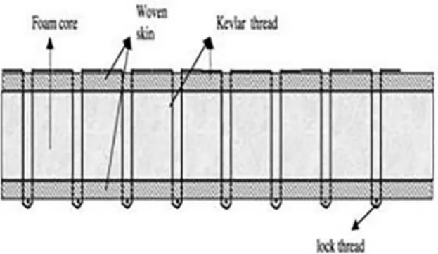
method was adopted for stitching shown in Figure1. Failure loads of the specimens were studied by varying stitch pitch distance. The results show the debonding area is less for lesser stitch density specimens. Figure 2 shows multiple needle sewing machine in which the knots linking needle and bobbin threads are formed at one surface of the laminate to
minimize the in plane fiber distortion. Pre-drilled sandwich
core is placed in between the glass fabric face sheet. The multiple needles with Kevlar yarn are inserted through the thickness of the face sheet and core. At the bottom of the panel a loop is formed. By using looper the lock thread is inserted with the help of raiper.
Designing the sandwich structure to with stand the shear loading remains an important problem. The problem is more
critical when lower stiffness foam cores subjected to high shear loading. The core first fails under shear because the
weakest component of the sandwich construction is the core (assuming perfect contact between the foam core and the skin). Therefore, the most important aspects of the structural behaviour of the sandwich panel are the shear deformable
core. So, the aim of the experiment is to determine the core
shear modulus of the sandwich construction with and without
stitching. The shear response of the sandwich panel with polyvinylchloride (PVC) was analysed.
2. Experiment Method
2.1 Materials and manufacturer
The core material selected for this study was Divinycell closed-cell ‘H’TM (manufactured by DIAB core, Sweden)
grade foam core (density = 80kg/m3, thickness = 10 mm, Shear strength= 1.15 MPa)10. This foam core was chosen because of its superior fatigue and impact resistance, damage
tolerance, light weight and excellent cost effectiveness.
The core material used in this study can be used for the
vast majority of composite applications where both hand
laminating and closed moulding process such as infusion
is employed. Woven glass fabric of weight 320 g/m2 with thickness of 10 mils woven open form saline treated E-glassTM
(manufactured by FRP services, Japan, density - 2.55 g/m3, Youngs modulus = 80 GPa) fabric cloth11 was used as face sheets. The open form cloth was selected for this work as
the resin is impregnated into the next layer of cloth easily
when compared to closed form cloth. The properties of
E-glass cloth are high stiffness, high strength to weight ratio, non-flammable, resistant to heat, good chemical resistance,
relatively insensitive to moisture and good electrical insulation. Yarn twisted in one direction is called single yarn,
and those twisted to the right and left are called S-twisted yarn and Z-twisted yarn respectively. Several single yarns twisted together are called as plied yarn. Single and plied yarns are used selectively according to the purpose. The
resin used to produce composites was GY 257 epoxy resin
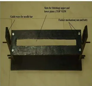
cured with hardener 2963 CH, which is having good wetting ability and appropriate viscosity at room temperature. The ratio of the resin to hardener is 100:45. Santhanakrishnan et al.12 developed a stitching machine shown in Figure 3,
which is used to stitch the sandwich panel at different pile orientation. Modified lock stitch method was adopted for
stitching. Figure 4 and 5 shows the front and top view of the stitching machine. Figure 6 shows multiple needles used for stitching. Pre-drilled sandwich core is placed in between the two face sheets (top and bottom) and is kept in between the slotted plates as shown in the Figure 3. The
Figure 1. Illustration of modified lock stitch method used in stitch
bonded sandwich constructions [Potluri et al9].
Figure 2. Illustration of multiple needle sewing machine for sandwich composite structures Potluri et al9.
Figure 3. Illustration of stitching machine for sandwich composite structures [Santhanakrishnan et al.12.
protector is fixed on the vertical member used for changing
the orientation of the panel. Through the guide ways multiple needles are moved up and down. Glass yarns are inserted in to holes of the needles. The multiple needles with glass yarn are inserted through the thickness of the face sheet and core. At the bottom of the panel a loop is formed. By using looper the lock thread is inserted with the help of raiper.
Five different types of panels were manufactured in this
work; unstitched sandwich panel and stitched sandwich
panel at different pile orientation (90º,45º,90º/45º and 90º/45º/90º). The 30×30 cm panels were fabricated using
the resin infusion process.
3. Core Shear Testing
Core shear testing was carried out according to ASTM C 273-61 standard “Standard Test Method for Shear Properties in Flatwise Plane of Flat Sandwich Constructions or Sandwich cores13. This test determines the shear strength parallel to the plane of the sandwich and shearing modulus associated with in a plane normal to the facings. As per the standard test specimen width not less than twice the thickness and a length not less than 12 times the thickness. Dimensions of the specimens are length (L) = 200 mm; width (B) = 50 mm and thickness (T) = 10.8 mm.
Test specimens are shown in Figure 7. The main objective
of this testing is to determine the interlaminar shear strength of stitched and unstitched sandwich specimens. Specimens
are glued to the testing apparatus with the of epoxy adhesive
having ahigh modulus of rigidity. The thickness of the plate varied according to the strength of sandwich, but the plate dimensions in such a way that that the line of action of the direct tensile or compressive force shall pass through the diagonally opposite corners of the sandwich, shown if
Figure 8.The fixture set up for the core shear test is shown
in Figure 9. Core shear testing was carried out at a constant
rate of 0.5 mm/min. Load versus displacement plots were
recorded during the test.
Five samples were carried out on each type of sandwich panel. Average values were taken for plotting the graph.
Figure 5. Top View of the Stitching Machine.
Figure 6. Multiple needles set up for stitching.
Figure 7. Specimens for core shear test.
4. Results and Discussion
Core shear testing was carried out at a constant rate of
0.5 mm/min. Load versus Displacement plots were recorded
during the test shown in Figure 10. Five tests were carried out on each type of sandwich panel. Core shear test results of the stitched and unstitched specimen are shown in Table 1. Shearing behaviour of the stitched foam sandwich panels
differ from an unstitched sandwich panel by their brittle nature.
The addition of stitches decreases the relative displacements of both skins in shearing conditions.
The shear modulus Gxz is determined according to the following equations:
(1)
Where P is the applied load (N); T, thickness (mm); B, width (mm); relative displacement (mm); and L is the
specimen length (mm). The maximum stress is given by
(2)
Where τmax is the maximum load at specimen failure. For unstitched specimen load is increasing up to the maximum
failure point and then specimen suddenly failed at the interface of the sandwich structures.
In all the stitched specimen the non-linearity observed
up to the maximum failure load after that significantly load drop was measured. The maximum failure load was observed in 90º/45º/90º specimens. The rigidity modulus of 90º/45º/90º is 832.5 %greater than the unstitched specimen, 85% greater than 90º specimen, 45.19% greater than 45º specimen and 18.6 % greater than 90º/45º specimen. The
same phenomenon was reported by Parambal Singh et al.6.
4.1 Failure mode
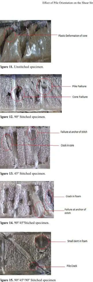
Katrzyna Grent et al.14 observed that composites with foam core deformed plastically. The similar type of failure
pattern was observed in unstitched specimen shown in figure
11. The failure of the unstitched sandwich specimens occurs in the foam core at an angle of 45º to the direction of the load. This failure propagates to the skin through the skin core interface. In stitched specimen, this phenomenon was delayed because the out of plane property is improved by stitching through its thickness. In stitched foam sandwich
panel foam does not play a significant role and the stitched
control the ability of the material to resist the shear load. In 90º stitched foam sandwich specimen the stitches break quickly one after the other when the damage starts which results in the fast degradation of the composite. In 45ºspecimen the initial failure takes place at the point of anchoring of the stitches. This failure is carried on the weak zone of yarns due to abrupt change of orientations.
The stitches are subjected to a combined tension and shearing state of stress. In 90º/45º specimens the rupture of
stitches at the anchoring point but it delayed when compared to 45º specimen. Initial crack is observed in 90º yarn followed
by 45º yarn. In 90º/45º/90º failure pattern is similar as like 90º/45ºpattern.The only difference is that the failure rate is
very slow. Failure pattern of the specimens are shown in Figure 11 - 15.
Figure 9. Core shear test fixture.
Figure 10. Core shear test results.
Table 1. Average shear strength and shear modulus (standard deviation in parenthesis)
Sl No. Sandwich Panel
Ultimate Shear Shear modulus
Strength,
σs(KPa)
G (MPa)
1 Unstitched 420 (0.12) 1.75(0.54)
2 Stitched- 450 1686(0.32) 11.24(0.43)
3 Stitched- 900 963(0.41) 8.78(0.39)
4 Stitched- 900/450 2443(0.33) 13.75(0.47)
5 Stitched- 90 0 /45 0/900 2844(0.32) 16.32(0.51)
G BL PT XZ d =
BL
P
(max) maxXZ
5. Conclusions
The effects of pile orientation on the shear strength of
stitched foam sandwich panel are carried out. Four types of
pile orientation are used; 90º,45º, 90º/45º and 90º/45º/90º.
The conclusions obtained from the result are as follows 1. Core shear test results show that the maximum failure
load was observed in 90º/45º/90ºspecimens. The rigidity modulus of 90º/45º/90º is 832.5 % greater than the unstitched specimen, 85% greater than 90º specimen, 45.19 % greater than 45ºspecimen and 18.6 % greater than 90º/45º specimen.
2. From the failure mode study it has been seen that
core damage is less for 90º/45º/90ºspecimen as
compared to the other specimens.
6. References
1. Lee GW, Choi JS, Lee SS, Park M, Kim J, Choe CR, et al. Mechanical properties and failure mechanism of the polymer composites with 3-dimensionally stitched woven fabric. Macromolecular Research. 2003;11(2):98-103.
2. Sharma SK, Sankar BV. Effects of Through-the-Thickness Stitching on Impact and Interlaminar Fracture Properties of Textile Graphite/ Epoxy Laminates. Haupton: NASA; 1995.
3. Vinson JR. The Behavior of Sandwich Structures of Isotropic and Composite Materials. Boca Raton: CRC Press; 1999.
4. Adams DO, Kessler JA, Nelson J, Bluth J, Kuramoto B. Development and Evaluation of Fracture Mechanics Test Methods for Sandwich Composites. In: Proceedings of the 2011 Federal Aviation Administration JAMS Technical Review Conference; 2011 Apr 20-21; San Diego, CA, USA.
5. Lascoup B, Aboura Z, Khellil K, Benzeggagh M, Maquet, J. On the interest of stitched sandwich panel. Compiègne: Dep GM-Polymers et composites BP; 2005.
6. Singh P, La Saponara V. Experimental Investigation on Performance
of Angle Stitched sandwich Structures. In: 45th AIAA/ASME/ASCE/ AHS/ASC Structures, Structural Dynamics & Materials Conference;
2004 Apr 19-22; Palm Springs, CA, USA.
7. Reis EM, Rizkalla SH. Material characteristics of 3-D FRP sandwich panels. Construction and Building Materials. 2008;22(6):1009-1018.
8. Wu Z, Xiao J, Zeng J, Liu J. Experimental on shear performance on
integrated 3D composite sandwich structures. Journal of Sandwich Structures & Materials. 2014;16(6):614-632.
9. Potluri P, Kusak E, Reddy TY. Novel stitch-bonded sandwich composite structures. Composite Structures. 2003;59(2):251-259.
10. Diab. Technical data. Available from: <www.diabgroup.com>.
Access in: 14/11/2017.
11. FRP Services & Company. Technical data. Available from: <www. frpservices.com>. Access in: 14/11/2017.
12. Santhanakrishnan R, Stanley D, Sanjeeviraja T, Stanley AJ. Effective Design Analysis of Fixture Development for Stitching a Sandwich
Panels in an Aerospace Application. Applied Mechanics and Materials. 2014;592-594:1055-1059.
Figure 11. Unstitched specimen.
Figure 12. 90º Stitched specimen.
Figure 13. 45º Stitched specimen.
Figure 14. 90º/45ºStiched specimen.
13. ASTM International. ASTM C 273-61 - Shear Properties in Flatwise Plane of Flat Sandwich Constructions or Sandwich Cores. West Conshohocken: ASTM International; 1988.