Abs tract
A secant function based shear deformable finite element model is developed for the flexural behavior of laminated composite and sandwich plates with various conditions. The structural kinematics of the plate is expressed by means of secant function based shear deformation theory newly developed by the authors. The theory possesses non-linear shear deformation and also satisfies the zero transverse shear conditions on top and bottom surfaces of the plate. The field variables are elegantly utilized in order to ensure C0 continuity requirement. Penalty parameter is implemented to secure the constraints arising due to independent field variables. A biquadratic quadrilateral element with eight nodes and 56 degrees of freedom is employed to discretize the domain. Extensive nume-rical tests for the flexural behavior of laminated composite and sandwich plates are conducted to affirm the validity of the present finite element model in conjunction with the improved structural kinematics. Influences of boundary conditions, loading conditions, lamination sequences, aspect ratio, span-thickness ratio, etc on the flexural behavior are investigated specifically and compared with the existing results in order to indicate the performance of the present mathematical treatment.
Key words
Laminated composite; sandwich plate; finite element analysis; static analysis; shear deformation theory.
Flexural behavior of general laminated composite and
sandwich plates using a secant function based shear
deformation theory
1 INTRODUCTION
The requirement of laminated composite and sandwich structures for the structural/components design in various disciplines such as aerospace, naval, automotive, civil, etc. has increased signifi-cantly over the past three decades due to their improved mechanical properties such as specific strength, specific stiffness; enhanced environmental properties such as their response to moisture
N ee raj G rov er Di pa k Kum ar Mai ti B hri gu Na th Si ng h*
Department of Aerospace Engineering, Indian Institute of Technology Kharagpur, West Bengal 721 302, India.
Latin American Journal of Solids and Structures 11 (2014) 1275-1297
and temperature; design flexibility due to their ability to tailor-made designs. In order to ensure the safe and reliable usage of these structures, there has been significant development towards the anal-ysis procedures. The structural kinematics is always of the primary concern since it describes the physical behavior of the structures. Moreover, an efficient numerical tool is mandatory for the in-vestigation of real application problems. With reference to structural kinematics of laminated com-posite and sandwich plates, classical laminated plate theory (CLPT) based upon Kirchoff’s hypothe-sis is inappropriate since it ignores the transverse shear deformation (Reissner, 1945; Mindlin, 1951). The early works considering the shear deformation were presented by Whintey (1969), Whitney and Pagano (1970), and Reissner (1975, 1979). However, they considered linear shear deformation and these theories are termed as first order shear deformation theories (FSDT). In order to ascertain zero transverse shear conditions at top and bottom surfaces, a shear correction factor is required in FSDT. In addition, the dependency of shear correction factor on lamination sequence, loading con-ditions etc. makes the FSDT less realistic (Pai, 1995). Various higher-order shear deformation theo-ries (HSDTs) were developed in the past by neglecting the assumptions of normality and straight-ness of the normal to mid plane after deformation as in case of CLPT and FSDT respectively. The-se theories consider non-linear shear deformation and the shear correction factor is not required. The HSDTs are either developed in the form of polynomial shear deformation theories (PSDT) by considering the Taylor’s series expansion in the in-plane displacement components (Levinson, 1980; Lo et al., 1977; Reddy, 1984; Pandya and Kant, 1988; Talha and Singh, 2010) or in the form of non-polynomial shear deformation theories (NPSDTs) by expressing the shear deformation in terms of a shear strain function (Touratier, 1991; Soldatos, 1992; Karama et al., 2009; Aydogdu, 2009; Meiche et al., 2011; Mantari et al., 2011; Hamidi et al., 2012; Mantari et al., 2012; Tounsi et al., 2013; Grover et al., 2013a). In addition to consider the realistic shear deformation, focus has been considered on the inter-laminar continuity (IC) and zig-zag (ZZ) requirement for modeling the mul-tilayered plate structures (Carrera, 2002). The layerwise (LW) and ZZ theories consider these re-quirements in addition to shear deformation. Some of the significant contributions towards ZZ and LW theories are due to Di Sciuva (1987), Murakami (1986), Cho and Parmerter (1992), Lee and Liu (1992), Ferreira et al. (2005), Roque et al. (2005), Pandit et al. (2009a, 2009b), Brischetto et al. (2009), Chakrabarti et al. (2011), Neves et al. (2012), Demasi, L. (2012, 2013) and Sahoo and Singh (2013). The various review articles on the modeling of laminated-composite and sandwich plates have been presented in the past (Noor and Burton, 1989; Reddy, 1991; Reddy and Robbins, 1994; Mallikarjuna and Kant, 1993; Liu and Li, 1996; Carrera, 1998, 2002, 2003; Zhang and Yang, 2009). Since the computational efforts for modeling the layered structures using HSDTs which are equiva-lent single layer theories (ESLs) are significantly less than LW and ZZ theories, researchers have constantly focused on the development and implementation of ESL theories despite their inability to predict ply level information.
equa-Latin American Journal of Solids and Structures 11 (2014) 1275-1297 tions. Among the various numerical investigations, Ritz methods (Kitipornchai, 1993), finite strip methods (FSM) (Li et al., 1986; Dawe and Wang, 1995), discrete singular convolution (DSC) meth-ods (Civalek, 2007), finite element methmeth-ods (FEM) (Pandya and Kant, 1988; Maiti and Sinha, 1996; Lal et al., 2008; Grover et al., 2013b; and Mantari et al., 2013), radial basis function (RBF) based methods (Ferreira et al., 2005; Roque et al., 2005; and Rodrigues et al., 2011), and isogeomet-ric analysis (Hughes et al., 2005; Thai et al., 2013) have been frequently considered for structural behaviors of laminated composite and sandwich plates.
In view of the above, the improved structural kinematics of the laminated composite and sand-wich plates is considered in terms of recently developed secant function based shear deformation theory (SFSDT) by the authors (Grover et al., 2013c). The theory possess non-linear shear stress distribution; satisfies the zero transverse shear conditions on top and bottom surfaces as a priori and therefore a shear correction factor is not required. However, the Navier solutions were imple-mented to show the validity of the theory for cross-ply plates subjected to simply supported bound-ary constraints. The finite element formulation of SFSDT is developed in the present work in order to assess the behavior of laminates subjected to different boundary constraints. However, the mini-mum continuity requirement for the considered structural kinematics is C1. The continuity re-quirement is reduced to C0 by making the adequate choice of field variables. Due to implementation of independent filed variables, additional constraints are satisfied by employing the penalty parame-ter. The methodology is validated for the flexural behavior of laminated-composite and sandwich plates by performing various numerical tests considering the influences of boundary conditions, loading conditions, span-thickness ratio, aspect ratio, and material orthotropic index in order to show the performance of secant function based shear deformable finite element. It is observed, by comparing the present results with those of published results, that the proposed approach is effi-cient for the prediction of flexural behavior of laminated-composite and sandwich plates at the simi-lar or less computational efforts as compared to other HSDTs. Furthermore, the generalized formu-lation enables the implementation of all existing shear strain shape function based shear defor-mation theories.
2 MATHEMATICAL FORMULATIONS
Latin American Journal of Solids and Structures 11 (2014) 1275-1297
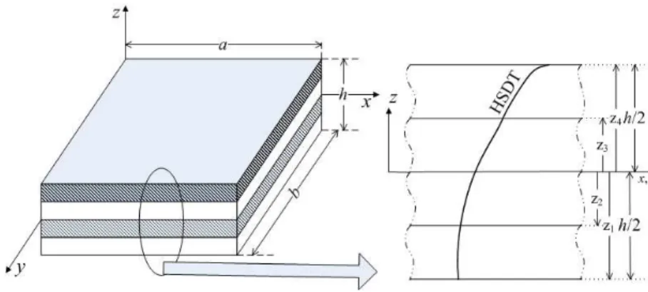
Figure 1 Schematic of a laminated plate
2.1 Constitutive relations
The material properties of the individual layers are expressed by stress-strain relations. Typically, the laminated composites are orthotropic in nature and the material behavior of kth orthotropic layer is governed by the following expression:
σ
{ }
5×1=
Q
ij⎡
⎣
⎤
⎦
(k)
ε
{ }
5×1 (1)
where
{ }
σ
=
σ
xx
σ
yyτ
xyτ
yzτ
zx{
}
Tand
{ }
ε
=
{
ε
xxε
yyγ
xyγ
yzγ
zx}
Tare the
stresses and strain components respectively while
⎡
⎣
Q
ij⎤
⎦
(k)is the transformed reduced stiffness
ma-trix expressed in terms of material properties (E1, E2, G12, G23, G13, ν12) and fiber orientation (α) of kth layer. It should be noted that the stress as well as strain in the transverse normal direction has been neglected in the present study.
2.2 Strain-displacement relations
The strain components given in Eq. (1) are further expressed in terms of displacement components assuming small displacements and rotations i.e., linear strain-displacements relations are considered as follows:
ε
{ }
=
⎡
u
,
xv
,
yu
,
y+
v
,
xv
,
z+
w
,
yu
,
z+
w
,
x⎣⎢
⎤
⎦⎥
T
(2)
Latin American Journal of Solids and Structures 11 (2014) 1275-1297 2.3 Displacement field
In the present work, the transverse normal after deformation is considered to be a function of thickness co-ordinate expressed in terms of a secant function based shear strain function (Grover et al., 2013c). Thus the hypothesis of straightness and normality is no longer valid as in case of CLPT and FSDT respectively. Moreover, the displacement field satisfies the zero transverse shear condi-tions at top and bottom surfaces as a priori and hence the requirement of satisfying these condicondi-tions is also eliminated.
u x
(
,y,z)
=u0(
x,y)
−z∂w0∂x + zsec rz
h
⎛ ⎝⎜
⎞ ⎠⎟−z
sec(r/ 2) 1+r
2tan r 2 ⎛ ⎝⎜ ⎞ ⎠⎟ ⎛ ⎝⎜ ⎞ ⎠⎟ ⎛ ⎝ ⎜ ⎜ ⎜ ⎜ ⎞ ⎠ ⎟ ⎟ ⎟ ⎟
θx
(
x,y)
v x
(
,y,z)
=v0(
x,y)
−z∂w0∂y + zsec rz
h
⎛ ⎝⎜
⎞ ⎠⎟−z
sec(r/ 2) 1+r
2tan r 2 ⎛ ⎝⎜ ⎞ ⎠⎟ ⎛ ⎝⎜ ⎞ ⎠⎟ ⎛ ⎝ ⎜ ⎜ ⎜ ⎜ ⎞ ⎠ ⎟ ⎟ ⎟ ⎟
θy
(
x,y)
w x
(
,y,z)
=w0(
x,y)
(3)
The in-plane displacement components (u, v) possess the through-thickness variation while the constant transverse displacement (w) is assumed over the thickness (h) of the plate as indicated in Eq. (3). The u0, v0, and w0 are the mid plane (z=0) displacement components in x, y, and z direc-tion respectively while θx and θy are the shear deformations. The parameter r is the shape parame-ter and its value is obtained as 0.1 in the post processing step by employing the inverse method (Grover et al., 2013c).
2.4 Continuity requirement
Due to presence of first order derivatives of w0 in the in-plane displacement terms as given in Eq. (3), the essential continuity requirement of the finite element is C1 continuity; however the compu-tational efforts to incorporate C1 continuity are quite large. Therefore, independent degrees of free-dom φx= w,x and φy = w,y, are adequately imposed in the displacement field to ensure C0
continui-ty requirement. The modified displacement field is then written as:
u
(
x
,
y
,
z
)
=
u
o(
x
,
y
)
−
z
φ
x(
x
,
y
)
+
⎡⎣
g
(
z
)
+
Ω
z
⎤⎦
θ
x(
x
,
y
)
v
(
x
,
y
,
z
)
=
v
o(
x
,
y
)
−
z
φ
y(
x
,
y
)
+
⎡⎣
g
(
z
)
+
Ω
z
⎤⎦
θ
y(
x
,
y
)
w
(
x
,
y
,
z
)
=
w
o(
x
,
y
)
(4)
Latin American Journal of Solids and Structures 11 (2014) 1275-1297
∂w
0/
∂x
−
φ
x=
0 ;
∂
w
0/
∂
y
−
φ
y=
0
(5)2.5 Element selection
In the framework of finite element method, the physical body is visualized as an assembly of ele-ments interconnected at nodes. The present displacement field possesses seven degrees of freedom
given by
{ }
q
=
⎡
⎣⎢
u
0v
0w
0θ
xθ
yφ
xφ
y⎤
⎦⎥
Tin order to ensure C0 continuity requirement.
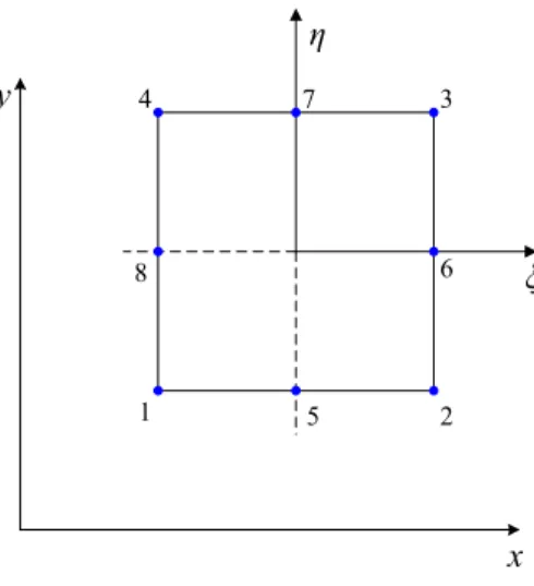
An eight noded isoparametric serendipity element with seven degrees of freedom at each node is implemented. The configuration of the element in natural co-ordinates (ξ−η) is described in Figure 2. The interpolation functions at ith node of the element (Cook, 1995) are given in Eq. (6).
Ni =
1
4
(
1+ξξi)
(
1+ηηi)
(
ξξi+ηηi−1)
for i=1,2,3,4 12 1−ξ 2
(
)
(
1+ηηi)
for i=5,71 2 1−η
2
(
)
(
1+ξξi)
for i=6,8⎧ ⎨ ⎪ ⎪ ⎪ ⎩ ⎪ ⎪ ⎪ (6)
Here, ξi and ηi are the values of natural co-ordinates at ith node. Since isoparametric formulation is
employed, the geometrical co-ordinates and nodal degrees of freedom are expressed using the same shape functions as follows:
x
=
N
ix
i i=18
∑
y
=
N
iy
i i=18
∑
(7a) u0 v0 w0 θx θy φx φy ⎧ ⎨ ⎪ ⎪ ⎪ ⎪ ⎪ ⎪ ⎪ ⎪ ⎪ ⎪ ⎪ ⎪ ⎪ ⎩ ⎪ ⎪ ⎪ ⎪ ⎪ ⎪ ⎪ ⎪ ⎪ ⎪ ⎪ ⎪ ⎪ ⎫ ⎬ ⎪ ⎪ ⎪ ⎪ ⎪ ⎪ ⎪ ⎪ ⎪ ⎪ ⎪ ⎪ ⎪ ⎭ ⎪ ⎪ ⎪ ⎪ ⎪ ⎪ ⎪ ⎪ ⎪ ⎪ ⎪ ⎪ ⎪ =Ni 0 0 0 0 0 0 0 Ni 0 0 0 0 0 0 0 N
i 0 0 0 0
0 0 0 N
i 0 0 0
0 0 0 0 N
i 0 0
0 0 0 0 0 N
i 0
0 0 0 0 0 0 N
i ⎡ ⎣ ⎢ ⎢ ⎢ ⎢ ⎢ ⎢ ⎢ ⎢ ⎢ ⎢ ⎢ ⎢ ⎢ ⎢ ⎢ ⎤ ⎦ ⎥ ⎥ ⎥ ⎥ ⎥ ⎥ ⎥ ⎥ ⎥ ⎥ ⎥ ⎥ ⎥ ⎥ ⎥
i=1 8
∑
u0i
v0i
w0i
θxi θyi φxi φyi ⎧ ⎨ ⎪ ⎪ ⎪ ⎪ ⎪ ⎪ ⎪ ⎪ ⎪ ⎪ ⎪ ⎪ ⎪ ⎩ ⎪ ⎪ ⎪ ⎪ ⎪ ⎪ ⎪ ⎪ ⎪ ⎪ ⎪ ⎪ ⎪ ⎫ ⎬ ⎪ ⎪ ⎪ ⎪ ⎪ ⎪ ⎪ ⎪ ⎪ ⎪ ⎪ ⎪ ⎪ ⎭ ⎪ ⎪ ⎪ ⎪ ⎪ ⎪ ⎪ ⎪ ⎪ ⎪ ⎪ ⎪ ⎪ (7b)
where, xi, yi are the nodal co-ordinates, uoi, voi, woi, θxi, θyi, φxi, and φyi are the nodal degrees of
Latin American Journal of Solids and Structures 11 (2014) 1275-1297 x y ξ η 1 2 3 4 5 6 7 8
Figure 2 The configuration of eight-noded finite element
2.6 Governing equations
The governing equations for the analysis of laminated composite and sandwich plates are obtained by implementing Lagrange Equation which is as follows:
∂Ul
∂ q
i
{ }
+∂Uc
∂ q i
{ }
+ ∂W ∂ q i{ }
=0 (8)where Ul is the strain energy due to linear strains, Uc is the strain energy due to imposition of
artificial constraints and W is the work done due to external loading. These terms are first ex-pressed for the jth element and then assembled over the complete domain. In order to facilitate fi-nite element implementation, the strains given by Eq. (2) are further expressed in terms of general-ized linear strains{el}as follows:
ε
{ }
5x1=
H
⎡⎣ ⎤⎦
5x13{ }
ε
l13x1 (9)
where
ε
l
{ }13x1
=
ε
1 0
ε
2 0ε
6 0k
1 0k
2 0k
6 0k
1 1k
2 1k
6 1ε
4 0ε
5 0k
4 2k
5 2{
}
T arethe components of generalized strains and functions of nodal field variables which are given explicit-ly in Appendix A along with the matrix [H]. The strain energy of the jth element due to linear strains is then obtained by implementing Eqs. (1), (4), (7) and (9) and written as follows:
U
l
(j)
=
1
2
{ }
ε
jT
σ
{ }
v∫
dv
=
1
2
{ }
ε
jT
Q
ij⎡
⎣
⎤
⎦
{ }
ε
j v∫
dv
=
1
2
{ }
ε
l jT
H
⎡⎣ ⎤⎦
jT
Q
ij⎡
⎣
⎤
⎦
⎡⎣ ⎤⎦
H
j{ }
ε
l j v∫
dv
=
1
2
{ }
q
jT
B
⎡⎣ ⎤⎦
jT
D
⎡⎣ ⎤⎦
⎡⎣ ⎤⎦
B
j
{ }
q
s∫
j
dxdy
=
1
2
{ }
q
jT
K
j⎡
⎣
⎤
⎦
{ }
q
jLatin American Journal of Solids and Structures 11 (2014) 1275-1297
where
{ }
q
=
⎡
⎣⎢
u
0v
0w
0θ
xθ
yφ
xφ
y⎤
⎦⎥
T(11)
The elemental strain energy is evaluated for all the elements (nel) in the domain and then as-sembled together to obtain total strain energy. The expression for total strain energy is given in Eq. (12)
U
l=
U
l(j) j=1 nel∑
=
1
2
{ }
q
T
K
⎡⎣ ⎤⎦
{ }
q
(12)The additional constraints (see Eq. (5)) due to incorporation of independent field variables are satisfied by employing the penalty parameter (γ, taken as 1×10⁶) and this leads to their contribu-tion towards the strain energy (Talha and Singh, 2010). The strain energy due to these constraints is obtained and given in the Eq. (13).
U
c
=
U
c(j)
j=1
nel
∑
=
γ
2
{ }
q
TK
c
⎡⎣ ⎤⎦
{ }
q
(13)U
c
(j)
=
γ
2
∂
w
0∂
x
−
φ
x⎛
⎝⎜
⎞
⎠⎟
jT
∂
w
0∂
x
−
φ
x⎛
⎝⎜
⎞
⎠⎟
j+
∂
w
0∂
y
−
φ
y⎛
⎝⎜
⎞
⎠⎟
jT
∂
w
0∂
y
−
φ
y⎛
⎝⎜
⎞
⎠⎟
j⎡
⎣
⎢
⎢
⎤
⎦
⎥
⎥
V∫
dV
(j) (14)The work done due to external load is obtained as follows:
W
=
W
j(e)
j=1 nel
∑
=
p
Aj(e)
∫
(x,
y)w.dA
j(e)
j=1 nel
∑
=
{
f
(e)}
j j=1
nel
∑
{ }
q
j
=
{ }
F
{ }
q
(15)Here
{ }
f
j=
0
0
p
0
0
0
0
0
⎡
⎣
⎤
⎦
; with p0 as the transverse load on the plate. For uniformly distributed load (UDL), p0 = q0 whilep
0=
q
0sin(
π
x
/
a
)sin(
π
y
/
b
)
for sinusoidal load (SSL). The following system of algebraic equations is obtained which can be solved to obtain the flexural response by substituting Eqs. (12), (14), and (15) in Eq. (8).K
+
γ
K
C⎡⎣
⎤⎦
{ }
q
=
{ }
F
(16)Latin American Journal of Solids and Structures 11 (2014) 1275-1297 the displacement based formulation; therefore special attention is required to evaluate the accurate nodal stresses.
3 NUMERICAL RESULTS AND DISCUSSIONS
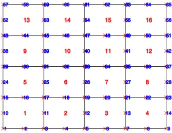
The present secant function based shear deformable finite element is assessed for flexural responses of laminated composite and sandwich plates. A generalized code is programmed in MATLAB envi-ronment using the present generalized finite element formulation. The plate is discretized with eight noded serendipity quadrilateral elements using an automatic mesh generation scheme. An automat-ed generatautomat-ed mesh for a square plate is shown in Figure 3 indicating the node numbering and ele-ment numbering scheme for a particular mesh size of 4×4. Selective integration Gauss-Quadrature technique is implemented to evaluate the domain integral since the direct application of the present finite element may induce shear locking especially for thin plates.
Figure 3 Node numbering1 and element numbering2 for a discretized plate with mesh size 4×4
The following degrees of freedom are restrained for different types of boundary conditions:
• Clamped condition (C):
u
0=
v
0=
w
0=
θ
x=
θ
y=
φ
x=
φ
y=
0
• Simply supported condition (S): o Edge parallel to x-axis:
u
0
=
w
0=
θ
x=
φ
x=
0
o Edge parallel to y-axis:
v
0
=
w
0=
θ
y=
φ
y=
0
The common material models used for the analyses are: Material Model 1 (MM1) - E1/E2 =25, G12/E2=0.5, G13/E2 =0.5, G23/E2 = 0.2, ν12 = 0.25 and Material Model 2 (MM2) - E1/E2 = C (var-iable), G12/E2=0.6, G13/E2 =0.6, G23/E2 = 0.5, ν12 = 0.25.
The displacements are evaluated at the nodal points while the stresses are primarily obtained at the Gauss points since the Gauss point stresses are most accurate (Cook, 1995). Gauss point
1 Cross mark ‘×’ indicate the node positions and corresponding numbers 2 Element number is shown at the middle of each quadrilateral element
Latin American Journal of Solids and Structures 11 (2014) 1275-1297
es are then extrapolated to the nodal points and then nodal averaging is performed in order to evaluate accurate nodal stresses. Non-dimensional forms given in Eq. (17) are implemented to ob-tain non-dimensional results to ensure the comparison with the existing results.
w
=
w
0a
2
,
b
2
⎛
⎝⎜
⎞
⎠⎟
100
E
2h
3b
4q
0⎛
⎝⎜
⎞
⎠⎟
σ
xxσ
yyτ
xyτ
yzτ
yz⎡
⎣
⎤
⎦
=
bq
h
0
⎛
⎝⎜
⎞
⎠⎟
h
b
σ
xxh
b
σ
yyh
b
τ
xyτ
yzτ
yz⎡
⎣
⎢
⎤
⎦
⎥
(17)
3.1 Four layered simply supported symmetric laminated plate
Latin American Journal of Solids and Structures 11 (2014) 1275-1297 Table 1 Flexural behavior of simply supported laminated plate [0/90/90/0] subjected to SSL
a/h Source
w
σ
xxσ
yyσ
xyσ
yzσ
xz(a/2,b/2,0) (a/2,b/2,h/2) (a/2,b/2,h/4) (0,0,h/2) (a/2,0,0) (0,b/2,0)
4 Present (4×4) 1.8904 0.5838 0.5216 0.0543 0.2759 0.2464
Present (6×6) 1.8995 0.6457 0.5772 0.0501 0.2854 0.2414
Present (10×10) 1.9013 0.6829 0.6104 0.0476 0.2899 0.2379
Present (14×14) 1.9015 0.6938 0.6202 0.0469 0.291 0.2369
Present (16×16) 1.9015 0.6965 0.6226 0.0467 0.2913 0.2367
Grover et al. (2013c) 1.8935 0.665 0.6322 0.0441 0.2389 0.2063
Mantari et al. (2012) 1.894 0.664 0.631 0.044 0.239 0.206
Reddy (1984) 1.893 0.665 0.632 0.044 0.239 0.206
Fiedler et al. (2010) 1.835 0.678 0.630 0.0453 0.270 0.237
Exact (Pagano, 1972) 1.954 0.72 0.663 0.047 0.291 0.219
10 Present (4×4) 0.7188 0.4639 0.3234 0.032 0.181 0.3516
Present (6×6) 0.7199 0.5132 0.3578 0.0296 0.1889 0.3454
Present (10×10) 0.7201 0.5427 0.3784 0.0282 0.1921 0.3405
Present (14×14) 0.7201 0.5514 0.3844 0.0278 0.1929 0.3389
Present (16×16) 0.7201 0.5535 0.386 0.0277 0.1931 0.3386
Grover et al. (2013c) 0.7147 0.5456 0.3888 0.0268 0.1531 0.2639
Mantari et al. (2012) 0.715 0.545 0.388 0.027 0.153 0.264
Reddy (1984) 0.715 0.546 0.389 0.027 0.163 0.294
Fiedler et al. (2010) 0.723 0.558 0.395 0.0274 0.180 0.234
Exact (Pagano, 1972) 0.743 0.559 0.401 0.028 0.196 0.301
100 Present (4×4) 0.4338 0.4445 0.2235 0.0253 0.1255 0.3821
Present (6×6) 0.4342 0.493 0.2478 0.0232 0.1328 0.3839
Present (10×10) 0.4342 0.5214 0.2621 0.0221 0.1362 0.3826
Present (14×14) 0.4342 0.5298 0.2663 0.0217 0.137 0.3813
Present (16×16) 0.4342 0.5318 0.2674 0.0216 0.1372 0.3809
Mantari et al. (2012) 0.435 0.539 0.271 0.021 0.112 0.289
Reddy (1984) 0.434 0.538 0.27 0.021 0.112 0.29
Fiedler et al. (2010) 0.434 0.539 0.271 0.0214 0.115 0.315
Exact (Pagano, 1972) 0.439 0.539 0.276 0.022 0.141 0.337
Further, the variation of transverse deflection is obtained over the length and width of the plate (a/h = 10) and the behavior is depicted in Figure 4. Figure 4(a) shows the variation of transverse deflection across x-axis at y = b/2 while Figure 4(b) represents the behavior at x= a/2 across y-axis. It is clear that maximum deflection is achieved at x = a/2 and y = b/2.
Latin American Journal of Solids and Structures 11 (2014) 1275-1297
Figure 4 Variation of transverse deflection across length and width of simply supported laminated plate [0/90/90/0] for a/h=10 (a) y = b/2 (b) x = a/2
Figure 5 Variation of normal stress,
σ
xx across thickness for the laminated plate [0/90/90/0]Latin American Journal of Solids and Structures 11 (2014) 1275-1297 The variation of normal stress (
σ
xx) across thickness is obtained for the same plate with a/h = 4, 10 and the behavior is presented in Figure 5 along with analytical solution of SFSDT [59]. The distribution of transverse shear stress (τ
yz) across transverse direction along with those obtainedfrom FSDT and HSDT (Reddy, 1984) implementing constitutive as well as equilibrium equations is shown in Figure 6. The comparison of the behavior ensures the efficiency of the present finite element method in the framework of SFSDT.
3.2 Influence of loading conditions
A three layered square laminated plate [0/90/0] constituted of equal thickness orthotropic (MM1) layers is analyzed under the influence of SSL and UDL. All the edges of the plate are simply sup-ported. Firstly, the plate is subjected to transverse SSL.
Table 2 Flexural behavior of three layered laminated plate [0/90/0] subjected to SSL.
a/h Source
w
σ
xxσ
yyσ
xyσ
yzσ
xz(a/2,b/2,0) (a/2,b/2,h/2) (a/2,b/2,h/6) (0,0,h/2) (a/2,0,0) (0,b/2,0)
4 Present 1.9253 0.7569 0.5012 0.0505 0.1568 0.2243
Mantari et al. (2012) 1.9222 0.733 0.502 0.05 0.183 0.202
Karama et al. (2009) 1.944 0.775 0.502 0.0516 0.191 0.22
Reddy (1984) 1.9218 0.734 -- -- 0.183 --
Exact (Pagano, 1970) 2.006 0.755 0.556 0.0505 0.217 0.282
10 Present 0.7173 0.5771 0.2677 0.0284 0.0896 0.3138
Mantari et al. (2012) 0.7131 0.568 0.269 0.028 0.103 0.244
Karama et al. (2009) 0.723 0.576 0.272 0.0281 0.108 0.272
Reddy (1984) 0.7125 0.568 -- -- 0.103 --
Exact (Pagano, 1970) 0.7405 0.59 0.288 0.0289 0.123 0.357
20 Present 0.5055 0.5435 0.2024 0.0234 0.07 0.335
Mantari et al. (2012) 0.5049 0.546 0.204 0.023 0.08 0.254
Karama et al. (2009) 0.508 0.548 0.205 0.0231 0.086 0.285
Exact (Pagano, 1970) -- 0.552 0.21 0.0234 0.094 0.385
50 Present 0.4432 0.5336 0.1814 0.0218 0.0638 0.3416
Mantari et al. (2012) 0.4439 0.54 0.184 0.022 0.076 0.258
Karama et al. (2009) 0.444 0.54 0.183 0.0216 0.079 0.289
Exact (Pagano, 1970) -- 0.541 0.185 0.0216 0.084 0.393
100 Present 0.4341 0.5321 0.1783 0.0216 0.0628 0.3425
Mantari et al. (2012) 0.4351 0.539 0.181 −0.021 0.075 0.258
Karama et al. (2009) 0.435 0.538 0.18 0.0213 0.078 0.289
Reddy (1984) 0.4342 0.539 -- -- 0.075 --
Latin American Journal of Solids and Structures 11 (2014) 1275-1297
Table 2 shows the transverse displacement and stresses of the plate in the non-dimensional forms at critical points along with the existing results for various span-to-thickness ratio (a/h = 4, 10, 20, 50, 100). The efficiency and applicability of present methodology is ascertained by comparing the re-sults with Mantari et al. (2012), Karama et al. (2009), Reddy (1984), and the exact solution (Pa-gano, 1970) for thick to thin laminates.
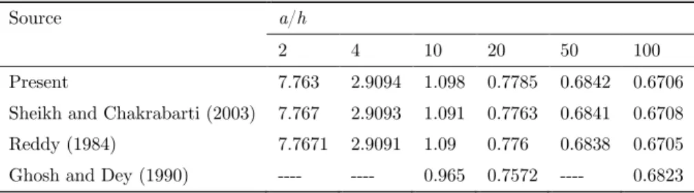
The same plate is then subjected to UDL and maximum transverse deflection is evaluated for the plate with various span-thickness ratios (a/h = 2, 4, 20, 20, 50, and 100). The obtained results are compared in Table 3 with the results obtained by Sheikh and Chakrabarti (2003), Reddy (1984), and Ghosh and Dey (1990). The comparison shows the applicability of SFSDT for the bend-ing behavior of laminated plates subjected to UDL.
Table 3 Flexural behavior of three layered laminated plate [0/90/0] subjected to UDL.
Source a/h
2 4 10 20 50 100
Present 7.763 2.9094 1.098 0.7785 0.6842 0.6706
Sheikh and Chakrabarti (2003) 7.767 2.9093 1.091 0.7763 0.6841 0.6708
Reddy (1984) 7.7671 2.9091 1.09 0.776 0.6838 0.6705
Ghosh and Dey (1990) ---- ---- 0.965 0.7572 ---- 0.6823
3.3 A nti-sym m etric cross ply lam inated plates
In order to investigate the influence of boundary conditions, a two layered anti-symmetric laminat-ed plate [0/90] is considerlaminat-ed. Both the orthotropic layers are of material, MM1 and have equal thickness.
Figure 7 Influence of boundary conditions on the non-dimensional deflection of anti-symmetric laminate [0/90] subjected to SSL.
Latin American Journal of Solids and Structures 11 (2014) 1275-1297 edges is clamped while the other pair is simply supported (SCSC). Non-dimensional deflection is obtained and the results are shown in Figure 7 along with the HSDT results (Reddy, 2002). The comparison shows the efficiency of SFSDT for the flexural behavior of laminates subjected to differ-ent combination of boundary constraints. Also, the behavior of normal stress
σ
xx across thicknessof the two layered simply supported plate (a/h=4) is obtained and presented in Figure 8.
Figure 8 Variation of normal stress
σ
xx across thickness for simply supported anti-symmetric plate [0/90] subjected to SSL (a/h=4)Figure 9 Simply supported anti-symmetric [0/90] laminated plate subjected to UDL
Latin American Journal of Solids and Structures 11 (2014) 1275-1297
absolute agreement with the existing results especially for thin plates (a/h=40). Moreover, they are more accurate than the results obtained by other equivalent single layer shear deformation theory for thick plates (a/h= 4, 10).
3.4 A ngle ply plates
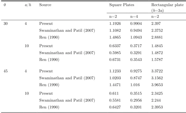
Flexural behavior of anti-symmetric angle ply plates [α/−α/…n layers] is investigated in this sec-tion. At first simply supported angle ply plates are considered. The non dimensional deflection of two layered and four layered square plates (b = a) with lamination sequences as [30/−30/…] and [45/−45/…] are obtained for the plates with span-thickness ratio of 4 and 10. The obtained results are presented in Table 4 along with the results by Swaminathan and Patil (2007) and the exact results by Ren (1990). It should be noted that Swaminathan and Patil (2007) implemented Reddy’s HSDT which possesses the same number of field variables as in the present SFSDT. It is concluded from the table that the present results are significantly different from Swaminathan and Patil (2007); however, the comparison with the exact solution (Ren, 1990) ensures the accuracy of the present results for thick plates. Moreover, the flexural analysis of two layered rectangular plates (b = 3a) is also performed and the results are presented in Table 4.
Table 4 Flexural behavior of anti-symmetric angle-ply plates.
θ a/h Source Square Plates Rectangular plate
(b=3a)
n=2 n=4 n=2
30 4 Present 1.1926 0.9904 2.397
Swaminathan and Patil (2007) 1.1082 0.9494 2.3752
Ren (1990) 1.4865 1.0943 2.8881
10 Present 0.6337 0.3717 1.4845
Swaminathan and Patil (2007) 0.5985 0.3291 1.4872
Ren (1990) 0.6731 0.3543 1.5787
45 4 Present 1.1233 0.9275 3.3722
Swaminathan and Patil (2007) 1.0203 0.8747 3.1562
Ren (1990) 1.4471 1.016 3.9653
10 Present 0.611 0.3515 2.3425
Swaminathan and Patil (2007) 0.5581 0.2956 2.244
Ren (1990) 0.6427 0.3201 2.3953
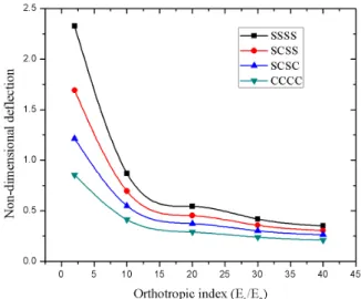
Latin American Journal of Solids and Structures 11 (2014) 1275-1297 stiffness and therefore lower deflections. Moreover, the decrement in transverse deflection is also observed from simply supported to clamped plate for a particular orthotropic index.
Figure 10 Effect of material orthotropic index on non-dimensional deflection.
3.5 T hree layered sandw ich plate subjected to uniform pressure
The flexural behavior of a sandwich plate constituted of two orthotropic face sheets and one ortho-tropic core [0/C/0] with its all edges simply supported under the influence of uniform pressure is examined in terms of deflection and stresses at critical points. The ratio of core-thickness (hc) to
total thickness (h) of the plate is 0.8 while the thickness of each face-sheet (hf) is 0.1 times the
thickness of plate. The material properties of the orthotropic core are given in Eq. (18).
[ ]
0.999781 0.231192 0 0 0
0.231192 0.524886 0 0 0
0 0 0.262931 0 0
0 0 0 0.266810 0
0 0 0 0 0.159914
core Q
⎡ ⎤
⎢ ⎥
⎢ ⎥
⎢ ⎥
=
⎢ ⎥
⎢ ⎥
⎢ ⎥
⎣ ⎦
(18)
(
)
(
)
(
)
(
)
(
)
(
)
(
)
1 1 3 2 3 2
1 1 2 1 3 2
0.999781 1 1 1
, , 0 , , , , , ,
2 2 2 2 2 2 2 2 2 2 2
1 1 2 1
, , , , , ,
2 2 2 2 2 5 2 2 2
xx xx xx xx xx xx
yy yy yy yy yy yy
a b a b h a b h a b h
w w
hq q q q
a b h a b h a b h
q q q
s s s s s s
s s s s s s
= = ‐ = ‐ = ‐
= ‐ = ‐ = ‐
(19)
Latin American Journal of Solids and Structures 11 (2014) 1275-1297
shows the comparison of the present results along with the established results. The comparison of the present results and the existing results with the exact solution reveals the superiority of the present theory. It is observed that the percentage difference of the present results from the exact solution (Srinivas, 1973) is 1.38% as compared to 3.03% of Pandya and Kant (1988), 2.26% of Touratier theory (Xiang et al, 2009), 1.83% of Karama’s theory (Xiang et al, 2009), 1.88% of Ferreira et al. (2003), 1.66% of Mantari et al. (2012) and 1.32% of ZZ results presented by Sahoo and Singh (2013). Thus, with the similar or less computational cost, SFSDT evaluates more accurate and efficient results for the flexural behavior of sandwich plates.
Table 5 Simply supported sandwich plate [0/C/0] subjected to uniform pressure.
R Theory
w
1xx
σ
σ
2xx3
xx
σ
σ
1yyσ
2yyσ
3yy5 Present 257.31 60.2354 46.7334 9.347 38.3672 30.104 6.021
Exact (Srinivas, 1973) 258.97 60.353 46.623 9.34 38.491 30.097 6.161
Pandya and Kant (1988a) 258.74 62.38 46.91 9.382 38.93 30.33 6.065
Touratier (Xiang et al., 2009) 253.989 60.123 47.097 9.419 38.249 30.187 6.037
Karama (Xiang et al., 2009) 253.638 60.124 46.703 9.34 38.242 30.02 6.004
Ferreira et al. (2003) 257.11 60.366 47.003 9.401 38.456 30.242 6.048
Mantari et al. (2012) 256.706 60.525 47.061 9.412 38.452 30.177 6.035
Sahoo and Singh (2013) 258.4292 60.0154 47.3145 9.4629 38.4372 30.4693 6.0939
10 Present 155.88 65.3656 49.4118 4.9412 43.3023 33.4607 3.3461
Exact (Srinivas, 1973) 159.38 65.332 48.857 4.903 43.566 33.413 3.5
Pandya and Kant (1988a) 152.33 64.65 51.31 5.131 42.83 33.97 3.397
Touratier (Xiang et al., 2009) 153.139 65.05 50.206 5.02 43.015 33.653 3.365
Karama (Xiang et al., 2009) 153.357 65.1 49.499 4.949 43.059 33.379 3.337
Ferreira et al. (2003) 154.658 65.381 49.973 4.997 43.24 33.637 3.364
Mantari et al. (2012) 155.498 65.542 49.708 4.971 43.385 33.591 3.359
Sahoo and Singh (2013) 159.1948 66.2209 49.5346 4.9535 44.1045 33.881 3.3881
15 Present 116.91 66.9887 49.3823 3.2922 45.9188 34.9904 2.3327
Exact (Srinivas, 1973) 121.72 66.787 48.299 3.232 46.424 34.955 2.494
Pandya and Kant (1988a) 110.43 66.62 51.97 3.465 44.92 35.41 2.361
Touratier (Xiang et al., 2009) 113.964 66.544 50.679 3.378 45.431 35.278 2.351
Karama (Xiang et al., 2009) 114.585 66.621 49.663 3.31 45.546 34.919 2.327
Ferreira et al. (2003) 114.644 66.92 50.323 3.355 45.623 35.17 2.345
Mantari et al. (2012) 115.919 67.185 49.769 3.318 45.91 35.081 2.339
Sahoo and Singh (2013) 121.56 67.667 48.9433 3.2629 47.0219 35.4735 2.364
3.6 Sandw ich plate subjected to SSL and different boundary constraints
Latin American Journal of Solids and Structures 11 (2014) 1275-1297 load is applied on the top surface of the plate. The face sheets of the plate under consideration are constituted of the material MM1, while the orthotropic core properties are taken as: E1c = E2c = 0.04E2, G12c = 0.016E2, G23c = G13c = 0.06E2 and ν12c =0.25. The thickness distribution of each layer is as [0.05h/0.05h/0.8h/0.05h/0.05h]. The flexural analysis is examined by assuming the SCSC and CCCC boundary conditions.
Figure 11 Five layered sandwich plate [0/90/C/0/90] subjected to SSL and different boundary conditions.
The effects of span-to-thickness ratio the boundary constraints on the transverse deflection are obtained and the behavior is characterized by implementing a double y-axis plot as indicated in Figure 11. The left y-axis shows the behavior of SCSC plate while right y-axis describes the behav-ior of CCCC plate. The results are also compared with the published results of Pandit et al. (2008) obtained using higher order zig-zag theory. It is observed that for thick plates (a/h < 10), SFSDT under-predicts the deflection as compared to zig-zag theory while for a/h >10, the behavior is in excellent agreement with Pandit et al. (2008).
4 CONCLUSIONS
conclud-Latin American Journal of Solids and Structures 11 (2014) 1275-1297
ed that the present finite element model in the framework of SFSDT is efficient in the computa-tional aspects as well as in terms of accuracy. Moreover, the proposed formulation enables the im-plementation of all existing shear deformation theories since it is presented in a generalized sense and thus it is more suitable for practical purposes.
References
Aydogdu, M. (2009). A new shear deformation theory for laminated composite plates. Composite Structures 89(1): 94-101.
Brischetto, S., Carrera, E., Demasi, L. (2009). Improved bending analysis of sandwich plates using a zig-zag function. Composite Structures 89: 408-415.
Carrera, E. (1998). Evaluation of layer-wise mixed theories for laminated plates analysis. AIAA Journal. 36(5): 830-839.
Carrera, E. (2002). Theories and finite elements for multilayered, anisotropic, composite plates and shells. Archives of Computational Methods in Engineering 9(2): 87-140.
Carrera, E. (2003). Historical review of zig-zag theories for multilayered plates and shells. Applied Mechanics Review 56: 65–75.
Chakrabarti, A., Chalak, H.D., Iqbal, M.A., Sheikh, A.H. (2011). A new FE model based on higher order zigzag theory for the analysis of laminated sandwich beam with soft core. Composite Structures 93(2): 271-279. Cho, M., Parmerter, R.R. (1992). An efficient higher-order plate theory for laminated composites. Composite Structures 20(2): 113-123.
Civalek, Ö. (2007). Free vibration and buckling analyses of composite plates with straight-sided quadrilateral domain based on DSC approach. Finite Elements in Analysis and Design 43(13): 1013-1022.
Cook, R.D. (1995). Finite element modeling for stress analysis, John Wiley & Sons Inc., Singapore.
Dawe, D.J., Wang, S. (1995). Spline finite strip analysis of the buckling and vibration of rectangular composite laminated plates. International Journal of Mechanical Sciences 37: 645-667.
Demasi, L. (2012). Partially zig-zag advanced higher order shear deformation theories based on the generalized unified formulation. Composite Structures 94: 363−375.
Demasi, L. (2012). Partially layer wise advanced zig zag and HSDT models based on the generalized unified formulation. Engineering Structures 53: 63-91.
Di Sciuva, M. (1987). An improved shear deformation theory for moderately thick multilayered anisotropic shells and plates. ASME Journal of Applied Mechanics 54(3): 589-596.
Ferriera, A.J.M., Roque, C.M.C., Martins, P.A.L.S. (2003). Analysis of composite plates using higher-order shear deformation theory and a finite point formulation based on the multiquadric radial basis function method. Composites Part B: Engineering 34(7): 627-36.
Ferreira, A.J.M., Roque, C.M.C., Jorge, R.M.N., Kansa, E.J. (2005). Static deformations and vibration analysis of composite and sandwich plates using a layerwise theory and multiquadrics discretizations. Engineering Analy-sis with Boundary Elements 29: 1104-1114.
Fiedler, L., Lacarbonara, W., Vestroni, F. (2010). A generalized higher-order theory for multi-layered, shear-deformable composite plates. Acta Mechanica 209: 85-98.
Ghosh, A.K., Dey, S.S. (1990). A simple element for the analysis of laminated plates. Composite Structures 44(3): 585-596.
Latin American Journal of Solids and Structures 11 (2014) 1275-1297
Grover, N., Singh, B.N., Maiti, D.K. (2013b). Analytical and finite element modeling of laminated composite and sandwich plates: An assessment of a new shear deformation theory for free vibration response. International Journal of Mechanical Sciences 67: 89−99.
Grover, N., Singh, B.N., Maiti, D.K. (2013c). New non-polynomial shear-deformation theories for structural be-havior of laminated-composite and sandwich plates. AIAA Journal 51(8): 1861-1871.
Hamidi, A., Zidi, M., Houari, M.S.A., Tounsi, A. (2012). A new four variable refined plate theory for bending response of functionally graded sandwich plates under thermo-mechanical loading. Composites Part B: Engineer-ing.
Hughes, T.J.R., Cottrell, J.A., Bazilevs, Y. (2005). Isogeometric analysis: CAD, finite elements, NURBS, ex-act geometry and mesh refinement. Computer Methods in Applied Mechanics and Engineering 194(39-41): 4135–4195.
Karama, M., Afaq, K.S., Mistou, S. (2009). A new theory for laminated composite plates. Proceedings of the Institute of Mechanical Engineers, Part L: Journal of Material, Design and Application 223: 53–62.
Khdeir, A.A., Librescu, L., Fredeirck, D. (1989). A shear deformable theory of laminated composite shallow shell type panels and their response analysis II: Static response. Acta Mechanica 77:1-12.
Kitipornchai, S., Xiang, Y., Wang, C.M., Liew, K.M. (1993). Buckling of thick skew plates. International Journal of Numerical Methods in Engineering 36(8): 1299–1310.
Lal, A., Singh, B.N., Kumar, R. (2008). Nonlinear free vibration of laminated composite plates on elastic foundation with random system properties. International Journal of Mechanical Sciences 50(7): 1203-1212. Lee, C.Y., Liu, D. (1992). An interlamininar stress continuity theory for laminated composite analysis. Com-puters & Structures 42(1): 69-78.
Levinson, M. (1980). An accurate, simple theory of statics and dynamics of elastic plates. Mechanics Research Communications 7(6): 343-350.
Li, W.Y., Cheung, Y.K., Tham, L.G. (1986). Spline finite strip analysis of general plates. ASCE Journal of Engineering Mechanics 112(1): 43–54.
Liu, D., Li, X. (1996). An overall view of laminate theories based on displacement hypothesis. Journal of Composite Materials 30(14): 1539–1561.
Lo, K.H., Christensen, R.M., Wu, E.M. (1977). A higher-order theory of plate deformation, part 2: Laminat-ed plates. ASME Journal of AppliLaminat-ed Mechanics 44(4): 669-676.
Maiti, D.K., Sinha, P.K. (1996). Bending, free vibration and impact responses of thick laminated composite plates. Computers & Structures 59(1): 115-129.
Mallikarjuna, Kant, T., (1993). A critical review and some results of recently developed refined theories of fi-ber-reinforced laminated composites and sandwiches. Composite Structures 23(4): 293-312.
Mantari, J.L., Oktem, A.S., Soares, C.G. (2011). Static and dynamic analysis of laminated composite and sandwich plates and shells by using a new higher-order shear deformation theory. Composite Structures 94(1): 37–49.
Mantari, J.L., Oktem, A.S., Soares, C.G. (2012). A new trigonometric shear deformation theory for isotropic, laminated composite and sandwich plates. International Journal of Solids and Structures 49(1): 43–53. Mantari, J.L., Soares, C.G. (2013). Finite element formulation of a generalized higher order shear defor-mation theory for advanced composite plates. Composite Structures 96: 545-553.
Meiche, N.E., Tounsi, A., Ziane, N., Mechab, I., Bedia, E.A.A. (2011). A new hyperbolic shear deformation theory for buckling and vibration of functionally graded sandwich plate. International Journal of Mechanical Sciences 53(4): 237–247.
Mindlin, R.D. (1951). Influence of rotary inertia and shear on flexural motions of isotropic elastic plates. ASME Journal of Applied Mechanics 18: 31-38.
Latin American Journal of Solids and Structures 11 (2014) 1275-1297
Neves, A.M.A., Ferreira, A.J.M., Carrera, E., Cinefra, M., Jorge, R.M.N., Soares, C.M.M. (2012). Static analysis of functionally graded sandwich plates according to a hyperbolic theory considering Zig-Zag and warping effects. Advances in Engineering Software 52: 30-43.
Noor, A.K., Burton, W.S. (1989). Assessment of shear deformation theories for multilayered composite plates. Applied Mechanics Review 42(1): 1-13.
Pagano, N.J. (1970). Exact solution for rectangular bidirectional composites and sandwich plates. Journal of Composite Materials 4(1): 20-34.
Pagano, N.J., Hatfield, H.J. (1972). Elastic behavior of multilayered bidirectional composites. AIAA Journal 10(7): 931-933.
Pai, P.F. (1995). A new look at shear correction factors and warping functions of anisotropic laminates. In-ternational Journal of Solids and Structures 32(16): 2295–2313.
Pandit, M.K., Sheikh, A.H., Singh, B.N. (2008). An improved higher order zigzag theory for the static analysis of laminated sandwich plate with soft core. Finite Elements in Analysis and Design 44: 602-10.
Pandit, M.K., Singh, B.N., Sheikh, A.H. (2009a). Stochastic free vibration response of soft core sandwich plates using an improved higher-order zigzag theory. ASCE Journal of Aerospace Engineering 23(1): 14-23. Pandit, M.K., Singh, B.N., Sheikh, A.H. (2009b). Stochastic perturbation-based finite element for deflection statistics of soft core sandwich plates with random material properties. International Journal of Mechanical Sciences 51(5): 363-371.
Pandya, B.N., Kant, T. (1988a). Higher-order shear deformable theories for flexure of sandwich plates— Finite element evaluations. International Journal of Solids and Structures 24(12): 1267-1286.
Pandya, B.N., Kant, T. (1988b). Finite element analysis of laminated composite plates using a Higher-order dis-placement model. Composite Science and Technology 32: 137-155.
Reissner, E. (1945). The effect of transverse shear deformation on the bending of elastic plates. ASME Journal of Applied Mechanics 12(2): 69-77.
Reissner, E. (1975). On transverse bending of plates, including the effect of transverse shear deformations. In-ternational Journal of Solids and Structures 11(5): 569-573.
Reissner, E. (1979). Note on the effect of transverse shear deformation in laminated anisotropic plates. Com-puter Methods in Applied Mechanics and Engineering 20(2): 203-209.
Reddy, J.N. (1984). A simple higher-order theory for laminated composite plates. ASME Journal of Applied Mechanics 51(4): 745-752.
Reddy, J.N. (1990). A review of refined theories of laminated composite plates. Shock Vibration & Digest 22(7): 3-17.
Reddy, J.N. (2002). Mechanics of laminated composite plates and shells: theory and analysis. CRC press. Reddy, J.N., Robbins, Jr D.H. (1994). Theories and computational models for composite laminates. Applied Me-chanics Review 47: 147–69.
Ren, J.G. (1990). Bending, vibration and buckling of laminated plates. In: Cheremisinoff NP, editor. Handbook of ceramics and composites, vol. 1. New York: Marcel Dekker 413–50.
Rodrigues, J.D., Roque, C.M.C., Ferreira, A.J.M., Carrera, E., Cinefra, M. (2011). Radial basis functions-finite differences collocation and a Unified Formulation for bending, vibration and buckling analysis of lami-nated plates, according to Murakami's zig-zag theory. Composite Structures 93(7): 1613-1620.
Roque, C.M.C., Ferreira, A.J.M., Jorge, R.M.N. (2005). Modelling of composite and sandwich plates by a trigonometric layerwise deformation theory and radial basis functions. Composites Part B: Engineering 36(8): 559–572.
Sahoo, R., Singh, B.N. (2013). A new inverse hyperbolic zigzag theory for the static analysis of laminated com-posite and sandwich plates. Comcom-posite Structures 105: 385-397.
Latin American Journal of Solids and Structures 11 (2014) 1275-1297
Soldatos, K.P. (1992). A transverse shear deformation theory for homogenous monoclinic plates. Acta Me-chanica 94(3-4): 195-220.
Srinivas, S. (1973). A refined analysis of Composite laminates. Journal of Sound and Vibration 30: 495-507. Swaminathan, K., Patil, S.S. (2007). Higher order refined computational model with 12 degrees of freedom for the stress analysis of antisymmetric angle-ply plates – analytical solutions. Composite Structures 80: 595-608. Talha, M., Singh, B.N. (2010). Static response and free vibration analysis of FGM plates using higher order shear deformation theory. Applied Mathematical Modelling 34(12): 3991-4011.
Thai, C.H., Ferreira, A.J.M., Carrera, E., Nguyen-Xuan, H. (2013). Isogeometric analysis of laminated com-posite and sandwich plates using a layerwise deformation theory. Comcom-posite Structures 104: 196-214. Tounsi, A., Houari, M.S.A., Benyoucef, S., Bedia, E.AA. (2013) A refined trigonometric shear deformation theo-ry for thermoelastic bending of functionally graded sandwich plates. Aerospace Science and Technology 24: 209-220.
Touratier, M. (1991). An efficient standard plate theory. International Journal of Engineering Science 29(8): 901-916.
Turvey, G.J. (1977). Bending of laterally loaded, simply supported, moderately thick, antisymmetrically lami-nated rectangular plates. Fiber Science and Technology 10: 211-232.
Whitney, J.M. (1969). The effect of transverse shear deformation on the bending of laminated plates. Journal of Composite Materials 3(3): 534-547.
Whitney, J.M., Pagano, N.J. (1970). Shear deformation in heterogeneous anisotropic plates. ASME Journal of Applied Mechanics 37(4): 1031-1036.
Xiang, S., Wang, K., Ai, Y., Sha, Y., Shi, H. (2009). Analysis of isotropic, sandwich and laminated plates by a meshless method and various shear deformation theories. Composite Structures 91: 31-37.
Zhang, Y.X., Yang, C.H. (2009). Recent developments in finite element analysis for laminated composite plates. Composite Structures 88(1): 147-157.
A ppendix A
ε
1 0=∂u0 ∂x ;
ε
20 =∂v0
∂y;
ε
6 0=∂u0 ∂y +
∂v0
∂x;
ε
4 0= ∂w0
∂y −
φ
y ;ε
5 0=∂w0 ∂x −
φ
x ;k10
=Ω∂
θ
x ∂x −∂
φ
x∂x ; k2 0
=Ω∂
θ
y ∂y −∂
φ
y∂y ; k6 0
=Ω ∂
θ
x∂y + ∂
θ
y∂x ⎛
⎝
⎜ ⎞⎠⎟ − ∂∂
φ
yx +∂φ
y ∂x ⎛⎝
⎜ ⎞⎠⎟ ;k11
=g(z)∂
θ
x ∂x ;k21
=g(z)∂
θ
y∂y ; k6 1
=g(z) ∂
θ
x ∂y +∂
θ
y ∂x ⎛⎝
⎜ ⎞⎠⎟ ;k42
=g'(z)
θ
y;k52=g'(z)
![Figure 4 Variation of transverse deflection across length and width of simply supported laminated plate [0/90/90/0] for a/h=10 (a) y = b/2 (b) x = a/2](https://thumb-eu.123doks.com/thumbv2/123dok_br/18885278.423686/12.892.228.706.87.293/figure-variation-transverse-deflection-length-simply-supported-laminated.webp)
![Table 2 Flexural behavior of three layered laminated plate [0/90/0] subjected to SSL](https://thumb-eu.123doks.com/thumbv2/123dok_br/18885278.423686/13.892.102.756.412.996/table-flexural-behavior-layered-laminated-plate-subjected-ssl.webp)
![Figure 9 Simply supported anti-symmetric [0/90] laminated plate subjected to UDL](https://thumb-eu.123doks.com/thumbv2/123dok_br/18885278.423686/15.892.272.569.586.827/figure-simply-supported-anti-symmetric-laminated-plate-subjected.webp)
![Table 5 Simply supported sandwich plate [0/C/0] subjected to uniform pressure.](https://thumb-eu.123doks.com/thumbv2/123dok_br/18885278.423686/18.892.153.788.315.894/table-simply-supported-sandwich-plate-subjected-uniform-pressure.webp)
