Abstract
In this work, the modal characteristics, including modal damping, of FRP composite skin, honeycomb core sandwich panels with arbitrary geometries are computed using a mixed finite element-meshless method. By using the element-meshless node distribution scheme in conjunction with the lagrangian quadrilateral interpolating func-tions, the continuity of inter-elemental displacements is assured. Since the distribution of the elements is not limited to the geome-try of the problem, any arbitrary geomegeome-try can be readily analysed by using the same node and element distributions. Using the first order shear deformation plate theory, together with a structural damping model, modal response results are produced for a number of sandwich panel geometries, including triangular, trapezoidal, circular as well as rectangular plates with different combinations of free and clamped edges. Results are compared with those reported in the literature, showing the viability and the accuracy of the method.
Keywords
Sandwich panel, FRP composite, honeycomb, modal, structural damping, meshless, finite element.
Prediction of Modal Damping of FRP-Honeycomb
Sandwich Panels with Arbitrary Geometries
1 INTRODUCTION
Aerospace structures bearing lateral loads are normally made from a light, spacer core sandwiched between two load-bearing skins. Increasingly, aerospace sandwich materials have fibre reinforced polymer (FRP) composites as their skins, and often a honeycomb material made from resin-soaked paper as their core. Compared to the traditional aluminium sandwich, not only do these materials enjoy a greater stiffness to weight ratio, they are also far more damped.
Sandwich modal damping is a function of several factors, including the sandwich skin/core damping and thickness ratio, its planar aspect ratio and its end conditions. With multilayer FRP
A. Abbasloo a M.R. Maheri b
a Department of Mechanical Engineering,
Shahid Bahonar University of Kerman, Iran. Email:
b Department of Mechanical Engineering,
Shahid Bahonar University of Kerman, Iran. Email: [email protected]
http://dx.doi.org/10.1590/1679-78252537
skins, the skin damping capacity will itself be a function of layer orientation and stacking sequence. (Maheri et al., 2008; Maheri and Adams, 1994; Thamburaj and Sun, 2001).
Some work on sandwich damping (Soovere, 1984; Meunier and Shenoi, 2001) have used a rate-dependent viscoelastic damping model while others (Maheri et al., 2008; Koo and Lee, 1995; Yim and Gillespie, 2000) have opted for a simpler rate-independent structural damping model. Most often, carbon and glass fibre FRP composites can be considered to be rigid enough to render the viscoelastic effect negligible. A viscoelastic analysis, however, lends itself more to situations where highly viscoelastic materials are purposely added to the structure as a constrained or free layer to increase damping.
Sandwich modal properties has long attracted a considerable attention. Various theories have been proposed regarding the mechanics of sandwich deformation and damping. Often, a simple, first order shear deformation theory has been used (Maheri et al., 2008; Liu and Zhao, 2001; Zhao and Stronge, 2006). To describe the sandwich shear deformation more accurately, higher order shear deformation theories have been developed (Liu and Zhao, 2007; Elmalichand Rabinovitch, 2012; Phan et al., 2013). Numerous factors influence sandwich damping, and these too have been the sub-ject of some investigations (Maheri et al., 2008; Maheri and Adams, 1994; Thamburaj and Sun, 2001; Yaman and Onal, 2015).
The sandwich panels considered in the above studies have generally been of a rectangular shape. The primary aim of the present work was to devise a method through which FRP-Honeycom sand-wich panels with any arbitrary geometry and boundary conditions could be readily and conveniently analysed for their modal characteristics, particularly structural damping. The first order shear de-formation theory is used for sandwich dede-formation since any refinement in the damping results pro-duced by a higher order theory is well within the expected tolerance of damping measurements. We have used a combination of the meshless node distribution and the finite element (FE) techniques in which, similar to the latter method, rectangular elements are arranged side by side so that they cover the domain of the problem, while the meshless technique is used to ensure the inter-elemental continuity of the displacement functions and their derivatives. The meshless node distribution whol-ly covers the problem domain, and the boundary elements are of the same rectangular shape as the elements that lie within the geometric domain. Since some boundary elements could extend beyond the geometric bonds of the problem, the actual boundary is defined at the integration stage where the energies are computed only within the problem domain. Because the geometric bounds of the particular problem are independent of the node and element distributions, the same predefined nod-al and elementnod-al distributions may be used to annod-alyse any arbitrary shape, thereby saving on com-putational and human resources.
The proposed method in the present work has been compared with the Rayleigh-Ritz analysis of (Maheri et al., 2008). It is noted that while any arbitrarily shaped plate can be solved using the present method, the Rayleigh-Ritz analysis is limited to the solution of rectangular plates.
report-2 THEORY
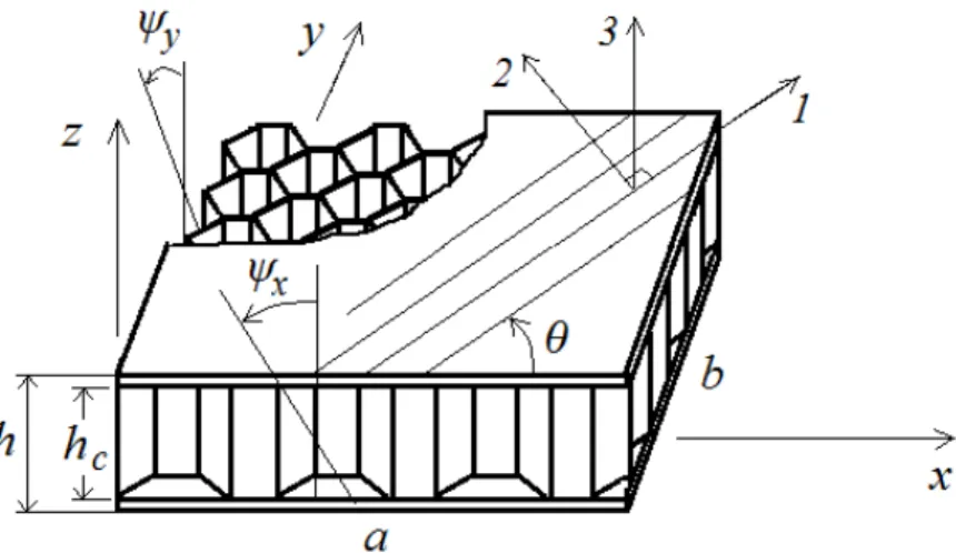
The discretization scheme used in the present work is based on a combination of the finite element and the meshless methods. Considering an element of a mid-plane symmetric sandwich plate with FRP skins and a honeycomb core (Figure 1), the displacements within the element are functions of the displacements in the sixteen surrounding nodes. As in the FE scheme, the sixteen-noded lagran-gian quadrilateral is duly used for interpolation. These sixteen nodes constitute part of the meshless support domain for the points inside the element.
Figure 1: Sandwich panel element in a meshless node distribution.
Shown in Figure 2 is a 3-D diagram of the sandwich plate and its assumed DOFs which include the displacement w in the z-direction, and the two total rotations
x and
y about the y- and the x-axes respectively. Each rotation comprises the rotation due to bending and the rotation due to transverse shear.Figure 2: 3-D vision of sandwich panel and its DOFs.
( , )
x x y yu
z
u
z
w
w x y
Using the following usual convention in referring to the stress and strain components,
xx 1,yy 2,zz 3,xz 4,yz 5,xy 6
Then strain components
are found from Equations (1) as
1 1
2 2
6
4 4
5 4
6
(
)
(
)
(
)
x y
x y
y x
z
x
z
z
y
z
w
x
w
z
y
z
y
x
(1)
Assuming that the strain energy of the sandwich element shown in Figure 1 is a piecewise func-tion of the strain energies of the skins and the core, then it can be written as
1( ) 2
1 2
1
(
)
1
(
)
2
2
c k
c
k e e
h L z
T k T
h
e c
z k
U
Q
dxdy dz
G
dxdy dz
(2)in which L is the total number of layers in both skins,
z
k andz
( 1)k are the distances from thesandwich mid-plane to the outer and the inner faces of the kth layer of the skins respectively, hc is
the core thickness, and
1Q
T
Q T
(3.1)
0 0
0
0 0
0
0
0 0
0 0
0
0
c xz
yz
G
G
Sym
G
where
Q
is the off-axis, plane stress orthotropic stiffness matrix for each layer k of the FRP lam-inate skins, and
G
c is the stiffness matrix of the core. The off-axis stiffness matrix Q is given in terms of the on-axis stiffness matrix,[ ]
Q
i j , whose components are given in terms of theortho-tropic elastic property constants of the skins as
2
1 12 1 2
2 2
1 12 2 1 12 2 1 2
2 1 12 2
2 12
23 12
0
0 0
0
0 0
[ ]
0 0
0
.
2(1
)
i j
Q
G
Sym
E
E E
E
E
E
E
E E
E
E
E
G
(4)
The stress and strain transformation matrices in equation (1) are given as
2 2 2 2
2 2 2 2
2 2 2 2
0
0
0
0
2
0
0
0
0
2
,
0 0
0
0 0
0
0 0
0
0 0
0
2
2
0
0
0
0
where
cos( ) and
sin( )
mn
mn
m
n
m
n
mn
mn
n
m
n
m
T
m
n
T
m
n
n
m
n
m
mn
mn
m
n
mn
mn
m
n
m
n
(5)
It is noted that Equations (3) and (4) reflect the assumption that while the in-plane damping of the honeycomb material can always be neglected with little loss of accuracy, the shear damping of the skins can be significant depending on the skin/core relative thickness.
Equation (1) in equation (2) will give
( ) ( ) 2 ( ) 2
4 5 4 5 1
1
( ) 2 ( ) 2 ( ) 2 ( ) ( ) ( ) 1 22 2 66 6 12 1 2 16 1 6 26 2 6
3 3 2 2
1
45 44 55
11
4 5
1
1
(
( (
)(
)
2
2
1 (
2
2
2
)
6
1
(
))d d )
(
)d d
2
e
e
L
k k k
e s k k
k
k k k k k k
k k s c xz yz
U
k Q
Q
Q
z
z
Q
Q
Q
Q
Q
Q
z
z
x y
k h
G
G
x y
in which ks is a shear correction factor, normally assumed to be about 5/6. For each node p, the
displacements can be written in terms of the 16-noded lagrangian interpolating functions (
i) as( , )
,
,
1,2,3 16
,
(
)
(
)
i i i x i xi i y yw x y
w
y
i
y
x
x
(7)Therefore, the curvatures
{ }
in equation (1) can be written as1
2
4
5
6
1, 2,3 16
(
)
,
i i i i ii i i
i
i i i
i i i i x y x y x y
x
y
w
x
w
y
i
y
x
(8)Substituting equation (8) in equation (6) will give the element’s strain energy as
e ij i j ij i xj
C
ij i y jD
ij xi xjF
ij yi yj ij xi y jU
A w w
B w
w
H
(9)in which
1
4
1 ( )
4 5( )5 45( )
1
(
)d d
2
(
(
1
(
)
2
)d d
(
)
)
e e Ls c s
j j
i i
ij xz yz k k
j j j j
i i i i
k
k k k
A
k h
G
G
x y
k
x
x
y
y
Q
Q
Q
x y
x
x
y
y
x
y
z
x
z
y
Ω (10.1)1 44( ) (
1 45
)
(
)
d d
(
(
) d d
e
e
i
ij xz j
i i k k s c L k k s j k
k h
G
x y
x
k
B
z
Q
Q
x y
1 45( ) (
1 55
)
(
)
d d
(
(
) d d
e
e
i
ij yz j
i i k k s c L k k s j k
k h
G
x y
y
k
C
z
Q
Q
x y
x
y
z
Ω (10.3) ( ) ( ) 1 ( ) ( ) 1 3 31 11 66
16 44 1
1
(
(
6
1
(
)
)d d )
(
)
d
(
)
2
(
d
)
e
e
j j
i i
ij k k
j j
i i
k k i j
L
k k
k
L
k k
s c xz
k
D
z
Q
Q
x
x
y
y
Q
x y
k
Q
h G
x y
x
y
y
x
z
z
z
(10.4) ( ) ( ) 1 ( ) ( ) 1 3 31 22 66
26 55 1
1
(
(
6
1
(
)
)d d )
(
)
d
(
)
2
(
d
)
e
e
j j
i i
ij k k
j j
i i
k k i j
L
k k
k
L
k k
s c yz
k
F
z
Q
Q
y
y
x
x
Q
x y
k
Q
h G
x y
y
x
x
y
z
z
z
(10.5) ( ) ( ) ( ) 1 ( ) ( ) 3 31 12 16 26
45 1
66 1
1
(
(
6
1
(
)
)d d )
(
)
d
2
(
)
d
e
e
j j j
i i i
L
k k k
k
ij k k
j i
k k i j
L
k k
s k
Q
Q
Q
x
y
x
x
y
y
Q
x y
k
Q
x y
y
x
H
z
z
z
z
,
1,2,3 16
i j
(10.6)
A convenient measure of structural damping is the specific damping capacity, SDC, usually shown by the symbol
(not to be confused with the plate rotations shown in Fig. 2), which is defined as the ratio of the damping energy to the maximum strain energy, thusU U
(11)
Similar to the strain energy, we assume that the damping energy of the sandwich element is al-so a piecewise function of the damping energies of the skins and the core, thus
1
( ) 2
1 2
1
(
d d )d
1
(
d d )d
2
2
c k
c
k e e
h L z
T k T
h
e s c
z k
U
R
x y
z
R
x y
z
(12)in which the skin damped stiffness matrix
[ ]
( )k S
1
s s
R
T
Q
T
(13.1)
R
c
cG
c(13.2)
where the damping matrixes
s and[ ]
c are the diagonal matrixes
11 22
13 23
12
0
0
0
0
0
0
0
0
0 0
0
0
0 0
0
0
0 0
0
0
s
(14.1)
0 0
0
0
0
0 0
0
0
0
0 0
0
0
0 0
0
0
0 0
0
0
0
c xz
yz
(14.2)
in which the factors
[ ]
i j quantify the proportion of the energy loss in each cycle of vibration dueto the relevant stress components.
It is noted that the skin and core stiffness Equations (3) and the analogous damping equations (14) reflect the assumption that while the in-plane damping of the honeycomb material can be ne-glected with little loss of accuracy, the shear damping of the skins can be significant depending on the skin/core relative thickness.
From equation (9), the element damping energy is accordingly given as
ij ij j ij y j ij ij ij e i j i x
C
iD
xi xjF
yi y jH
xi yjU
A w w
B w
w
(15)in which
1
( ) ( ) ( )
44 55 45
1
1
(
)d d
2
(
(
1
(
)
2
(
))
d d
)
e
e
L
j j
i i
ij xz yz k k
j j j j
i i i
s c xz yz s
k
k k k i
A
k h
G
G
x y
k
x
x
y
y
R
R
R
x y
x
x
y
y
x
y
y
x
z
z
Ω
( ) 4 ) 1 1 ( 5 4 4
d d
(
(
)
(
)
d
d
e e
s c xz L
k
s j
k
i
ij xz j
k
i i
k k
k h
G
x y
x
k
R
x y
x
B
z
z
R
y
Ω (16.2) ( ) ( ) 11 45 55
d d
(
(
) d
(
)
d
e e
s c yz L
s j
k
i
ij yz j
k i k i k k
k h
G
x y
y
k
x y
x
R
y
C
z
z
R
Ω (16.3)3 3 ( ) ( )
1 11 66
( ) ( )
16 44
1
1 1
1
(
(
6
1
)d d )
(
)
(
)
(
)
d d
(
)
2
e e L k Ls c xz xz
j j
k i k i
ij k k
j j
k i k
k k
i
k i j
x
x
y
y
x y
k
h
G
x y
x
y
y
x
D
z
z
R
R
R
R
z
z
(16.4)3 3 ( ) ( )
1 22 66
( ) ( )
26 55
1
1 1
1
(
(
6
1
)d d )
(
)
(
)
(
)
d d
(
)
2
e e L k Ls c yz yz
j j
k i k i
ij k k
j j
k i k
k k
i
k i j
y
y
x
x
x y
k
h
G
x y
y
x
x
y
F
z
z
R
R
R
R
z
z
(16.5) 1 13 3 ( ) ( ) ( )
1 12 16 26
( ) ( )
66 45 1
1
(
(
6
1
)d d )
(
)
d d
(
2
)
(
)
e ej j j
k i k i k i
ij k k
j k k L k L s k i
k k i j
x
y
x
x
y
y
x
H
z
z
R
R
R
R
y
k
R
z
z
x
y
y
x
,
1,2,3 16
i j
(16.6)
The element’s kinetic energy is given as
2 2 3 3 3 2 2
1
(2 (
)
( (
)
)(
))d d
2
2
1
1
e
e s c s c c c x y
T
h
h w
h
h
h
x y
Ω (17)
in which
is the natural frequency, h is the total panel thickness, and
s and
c
are skin and core mass densities respectively. Substituting for w,
x and
y from equation (7) in equation (17)will give the latter equation as
2
(
(
))
e ij i j ij xi x j yi yj
in which
3 3 3
(
)
d d
,
1,2,3 16
( (
)
,
1
2
4
)
d d
e
e
s c
ij i j
ij s c c c i j
m
h
h
x y
i j
I
h
h
h
x y
Ω
Ω
(19)
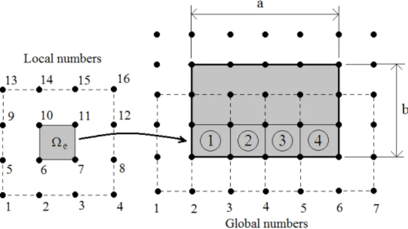
The displacements within each element of the discretised plate are computed from the dis-placements in the sixteen nodes that immediately surround the element (Figure 3) using the lagran-gian quadrilateral interpolating functions. Hence, the displacement functions in each element 1 are computed from the nodes that are shared by that element and the three successive neighboring elements on each side. The sixteen nodes that surround the element are effectively the support do-main that is used in the meshless method. This support dodo-main has an overlap with the surround-ing elements which should ensure the continuity of the displacements and their first and second derivatives at the elements’ boundaries.
Figure 3: Elements and their shared domains in a rectangular plate.
The total strain, damping and kinetic energies of the plate in terms of the elemental energies are given respectively as
1 1 1
,
,
n n n
e e e
e e e
U
U
U
U
T
T
(20)in which n is the number of elements. Since the total energy of the system is constant at any given time, one may write
constant,
0 ,
1, 2,3
i xi yi
U
T
w
U
T
i
N
U
T
(22)in which N is the total number of nodes. One may further write
2
1, 2,3
[ ]
,
[ ]
,
i i i i xi xi xi xi yi yi yi yiU
T
w
w
w
w
U
T
K
M
i
N
U
T
(23)in which [K] and [M] are the stiffness and mass matrices respectively. In order to determine the
elements of the stiffness and mass matrices of the panel, the elemental stiffness and mass matrices are considered
1,2,
[ ]
,
3 1
6
e i i e e xi xi yi e yi
U
w
w
U
K
i
U
(24)
2
[
]
,
1,2,
3 1
6
e i
i e
Using Equation (9) in equation (24), the elemental stiffness matrix is given as
**
*
e
Sy
A
B
C
K
D
H
F
m
(26)
in which
* * *
,
1,2,3 16
,
ij ij ji
ij ij ji
ij ij ji
A
A
A
D
D
D
F
i
F
j
F
(27)where Aij, Bij etc. have been given in Equations (10).
Similarly, the elemental mass matrix is given by Equations (18) and (25) as
*
*
*
0
0
0
eSy
M
I
I
m
M
(28)
in which
*
*
,
,
1,2,3 1
6
ij ij ji
ij ij ji
i
M
I
I
j
m
m
I
(29)where mij and ij
I
have been given in Equations (19).As shown in Figure 3, the nodes are denoted by both the local as well as global numbers. The element matrices [Ke] and [Me] are obtained using the local numbers, and the elements of these
ma-trices are lodged in the global mama-trices [K] and [M] using the interrelationship between the local
and the global numbers, thus obtaining the full global matrices. By substituting these matrices in Equations (23) before substituting the resulting equations into Equation (22), the following general-ized eigenvalue problem is obtained, the solution of which yields the natural frequencies and mode shapes of the panel
2
0 ,
1, 2, 3
i x i
w
K
M
i
N
The eigenvector produces nodal displacements that have been assigned a global number. Again, the interrelation between the local and the global nodal numbers is used to determine the local nodal displacements, and hence the strain and damping energies, of each element. The SDC for each mode is then computed by using the first two of the energy equations (20) in equation (11).
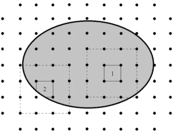
The method of solution in this study can be generalized for a panel with any arbitrary shape, as well as a rectangular geometry. In Figure 4, one such arbitrary shape is considered. The nature of the node distribution shown is what is typically required for the analysis, in that the extension of node distribution beyond the boundary is needed to provide the support domain for the boundary elements.
Figure 4: Defining the geometry of the problem.
As the figure indicates, for an arbitrary geometry two types of elements are used. The type 1 el-ement lies entirely within the panel and, therefore, is the same elel-ement as previously introduced in Figure 1. However, the type 2 element shown in Figure 5, lies on the plate boundary and is no long-er of a rectangular shape. In ordlong-er to compute the stiffness and mass matrices of this element, it is only necessary to carry out the integrals in Equations (10) and (19) within the geometric bounds of this element.
Figure 5: The type 2 element.
It is possible to extend the analysis in an analogous manner to include the through-thickness dimension as well, thereby removing the need for the requirement of an explicit formulation for the lateral shear deformations. However, the solution would obviously expend a substantially more computational resources than a two-dimensional analysis.
3 RESULTS
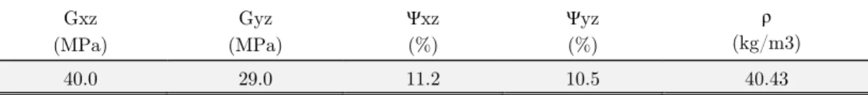
The sandwich panels considered are made from CFRP skins and aluminium or Nomex honeycomb core materials. The mechanical and damping properties of the skins and of the core are given in the following tables. It is noted that these data are actual test results which have been obtained in pre-vious works for the CFRP skin (Maheri et al., 2008) and the honeycomb core (Adams and Maheri, 1993). The honeycomb web is aligned along the x direction (Figure 2).
E1 (GPa)
E2 (GPa)
G12 (GPa)
Ψ1 (%)
Ψ2 (%)
Ψ12 (%)
Ψ13 (%)
Ψ23 (%) 12
ρ
(kg/m3)
271.0 6.02 5.46 0.45 7.30 8.16 8.16 8.16 0.34 1563.3
Table 1: [-60, 0, 60] CFRP skin mechanical and damping data. Gxz
(MPa)
Gyz (MPa)
Ψxz (%)
Ψyz (%)
ρ
(kg/m3)
140.0 75.4 0.74 1.02 40.39
Table 2: Aluminium core honeycomb mechanical and damping data. Gxz
(MPa)
Gyz (MPa)
Ψxz (%)
Ψyz (%)
ρ
(kg/m3)
40.0 29.0 11.2 10.5 40.43
Table 3: Nomex core honeycomb mechanical and damping data.
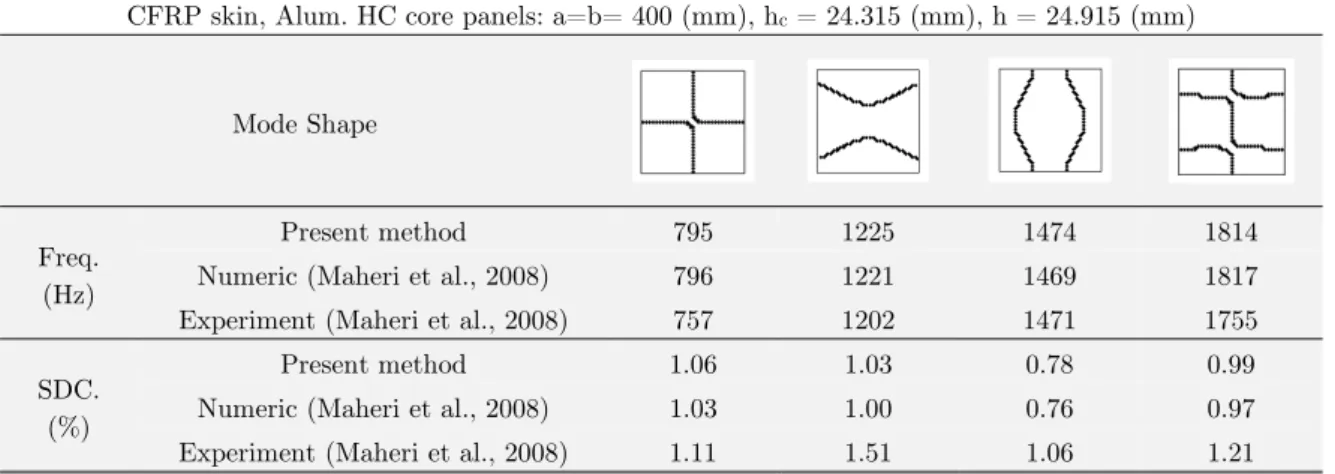
Modal response results were obtained for a number of mid-plane symmetric, carbon fibre rein-forced polymer (CFRP) skin, honeycomb core sandwich panels with arbitrary geometries and differ-ent boundary conditions. Direct comparison with published results were possible only in the case of rectangular plates with all-free boundary conditions (Table 4), since these were the only compatible published results available.
air-CFRP skin, Alum. HC core panels: a=b= 400 (mm), hc = 24.315 (mm), h = 24.915 (mm)
Mode Shape
Freq. (Hz)
Present method 795 1225 1474 1814
Numeric (Maheri et al., 2008) 796 1221 1469 1817
Experiment (Maheri et al., 2008) 757 1202 1471 1755
SDC. (%)
Present method 1.06 1.03 0.78 0.99
Numeric (Maheri et al., 2008) 1.03 1.00 0.76 0.97
Experiment (Maheri et al., 2008) 1.11 1.51 1.06 1.21
Table 4: Comparison of the present results with those of (Maheriet al.,2008) for a symmetric, CFRP skin, aluminium HC core sandwich panel
In Table 5, the results of a mesh-refinement examination have been tabulated for the first four modes of the above plate. These results show that while convergence of the SDC results in all modes occurs for as coarse as a 6 6 nodes mesh, a somewhat finer 10 10 mesh would suffice to ensure of a complete convergence in both the frequency and damping values in all the modes con-sidered. The present results were obtained using a 14×14 mesh.
CFRP skin, Alum. HC core panels: a=b= 400 (mm), hc = 24.315 (mm), h = 24.915 (mm)
Quantity of nodes
Freq. (Hz)
SDC.
(%) Freq. (Hz)
SDC.
(%) Freq. (Hz)
SDC.
(%) Freq. (Hz)
SDC. (%)
4×4 803.9 1.05 1358.7 1.06 1719.3 0.74 2090.9 0.98
6×6 798.5 1.06 1251.6 1.04 1522.8 0.77 1861.4 0.98
8×8 796.1 1.06 1227.9 1.03 1479.0 0.78 1818.9 0.99
10×10 795.6 1.06 1225.9 1.03 1475.3 0.78 1815.1 0.99
12×12 795.5 1.06 1225.6 1.03 1474.8 0.78 1814.4 0.99
14×14 795.4 1.06 1225.4 1.03 1474.3 0.78 1814.2 0.99
16×16 795.4 1.06 1225.4 1.03 1474.3 0.78 1814.2 0.99
Table 5: An examination of the mesh refinement requirement for complete convergence.
CFRP skin, Nomex. HC core panels: a=b= 400 (mm), hc=24.315, h= 24.915 (mm)
Mode Shape (CCCC)
Freq. (Hz) 814.1 1239.0 1347.6 1665.1
SDC. (%) 9.7745 9.8721 10.0962 10.2235
Mode Shape (CCCF)
Freq. (Hz) 583.7 968.8 1094.5 1400.8
SDC. (%) 9.0122 8.8828 9.5757 9.7142
Mode Shape (CCFF)
Freq. (Hz) 306.0 721.3 800.3 1154.7
SDC. (%) 6.1249 8.0177 8.3659 9.0493
Mode Shape (CFCF)
Freq. (Hz) 605.0 713.6 1150.4 1211.0
SDC. (%) 9.6462 8.8021 8.7383 9.9814
Mode Shape (CFFF)
Freq. (Hz) 196.1 355.4 725.4 936.9
SDC. (%) 4.4649 6.2149 8.0913 8.3440
Mode Shape (FFFF)
Freq. (Hz) 595.9 889.5 1012.8 1125.4
SDC. (%) 5.9674 6.7851 7.1415 8.2916
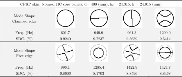
CFRP skin, Nomex. HC core panels: d= 400 (mm), hc,= 24.315, h = 24.915 (mm)
Mode Shape Clamped edge
Freq. (Hz) 601.7 949.9 961.3 1299.0
SDC. (%) 9.9240 9.7237 9.5659 9.5414
Mode Shape Free edge
Freq. (Hz) 896.1 1285.4 1422.9 1424.7
SDC. (%) 6.8606 8.1703 8.8596 8.8468
Table 7: Modal characteristics results for the symmetric, CFRP skin, Nomex. HC core circular panels with free and clamped edges.
CFRP skin, Nomex. HC core panels: a=b= 400 (mm), hc,= 24.315, h= 24.915 (mm)
Mode Shape CCC
Freq. (Hz) 1348.7 1902.1 2185.1 2488.3
SDC. (%) 10.4005 10.4153 10.4806 10.5082
Mode Shape CCF
Freq. (Hz) 787.9 1268.7 1615.5 1820.5
SDC. (%) 9.1864 9.6788 9.6950 9.9518
Mode Shape CFF
Freq. (Hz) 292.8 733.6 901.3 1291.1
SDC. (%) 5.9824 7.9784 7.4185 9.0745
Mode Shape FFF
Freq. (Hz) 837.2 1116.7 1407.5 1420.5
SDC. (%) 6.6980 7.6200 8.7411 8.5280
Table 8: Modal characteristics results for the symmetric, CFRP skin, Nomex. HC core triangular panels with different boundary conditions.
CFRP skin, Nomex. HC core panels: a=b= 400 (mm), hc =24.315, h= 24.915 (mm)
Mode Shape CCCC
Freq. (Hz) 1030.3 1419.7 1751.8 1882.7
SDC. (%) 10.1838 10.1574 10.3458 10.2493
Mode Shape CCCF
Freq. (Hz) 624.3 1088.5 1261.7 1577.5
SDC. (%) 8.7628 9.4860 9.1760 9.8772
Mode Shape CCFF
Freq. (Hz) 510.7 844.6 1238.1 1340.2
SDC. (%) 7.9008 8.7065 9.1239 9.3688
Mode Shape CFFF
Freq. (Hz) 211.9 511.2 676.7 1056.4
SDC. (%) 5.2095 6.5687 7.9930 8.4498
Mode Shape FFFF
Freq. (Hz) 721.5 906.0 1169.1 1271.3
SDC. (%) 6.4716 7.1738 8.0930 8.2458
Table 9: Modal characteristics results for the symmetric, CFRP skin, Nomex. HC core Trapezoid panels with different boundary conditions.
The results in these tables show that a correlation generally exists between the amount of the fixity of the plate and the modal damping, in that damping increases with the number of fixed edg-es. Restricted edges inhibit the movement of the skins relative to each other and this increases the degree of the interlocking between the lateral displacement of the plate and the shear deformation of the core, resulting in increased core damping. Furthermore, increased fixity of the panel makes modal damping increasingly invariant of the sandwich mode shape.
/ 2
a
a
4 CONCLUSIONS
Modal damping of sandwich panels comprising FRP skins and a honeycomb core can be computed using the mixed finite element-meshless technique. This is a viable and accurate method for predict-ing the modal response of sandwich panels with arbitrary geometries and different boundary condi-tions. The method is versatile, in that it can readily and conveniently use the same initially set-up node and element distributions to analyse different geometries. Furthermore, the continuity of the displacements at the elements’ boundaries are assured.
A number of sandwich panels with different geometries and boundary conditions were considered and, where possible, the modal characteristics, including the damping results were compared with those reported in the literature, whereupon it was shown that a high degree of correlation exists between the two sets of results. It was further shown that as the number of fixed edges increases, the sandwich damping increases and it becomes increasingly invariant of the sandwich mode shape.
References
Adams, R.D., Maheri, M.R., (1993). The dynamic shear properties of structural honeycomb materials. Composites Science and Technology 47: 15-23.
Elmalich, D., Rabinovitch, O., (2012). A high-order finite element for dynamic analysis of soft-core sandwich plates. Journal of Sandwich Structure and Materials 14(5): 525–555.
Koo, K.N., Lee, I., (1995). A refined analysis of vibration and damping for anisotropic laminates in cylindrical bend-ing. Journal of Sound and Vibration 184(4): 553-566.
Liu, Q., Zhao, Y., (2001). Prediction of Natural Frequencies of a Sandwich Panel Using Thick Plate Theory. Journal of Sandwich Structure and Materials 3: 289-309.
Liu, Q., Zhao, Y., (2007). Effect of Soft Honeycomb Core on Flexural Vibration of Sandwich Panel using Low Order and High Order Shear Deformation Models. Journal of Sandwich Structure and Materials 9: 95-108.
Maheri, M.R., Adams, R.D., (1994). Steady-state flexural vibration damping of honeycomb sandwich beams. Compo-sites Science and Technology 52: 333-347.
Maheri, M.R., Adams, R.D., Hugon, J., (2008). Vibration damping in sandwich panels. Journal of Materials Science 43: 6604-6618.
Meunier, M., Shenoi, R.A., (2001). Dynamic analysis of composite sandwich plates with damping modelled using high-order shear deformation theory. Composite Structures 54: 243-254.
Phan, C., Frostig, Y., Kardomateas, G.A., (2013). Free vibration of unidirectional sandwich panels, Part II: Incom-pressible core. Journal of Sandwich Structure and Materials 15(4): 412–428.
Soovere, J., (1984). Dynamic Response of Acoustically Excited Stiffened Composite Honeycomb Panels. PhD Thesis, ISVR: University of Southampton.
Thamburaj, P., Sun, J.Q., (2001). Effect of Material and Geometry on the Sound and Vibration Transmission across a Sandwich Beam. Journal of Vibration and Acoustics 123: 205-212.
Yaman, M., Onal, T., (2015). Investigation of dynamic properties of natural material-based sandwich composites: Experimental test and numerical simulation. Journal of Sandwich Structure and Materials 0(00): 1–18.
Yim, J.H., Gillespie, J.W., (2000). Damping characteristics of 0° and 90° AS4/3501-6 unidirectional laminates includ-ing the transverse shear effect. Composite Structures 50: 217-225.