Rodrigo da Cunha Antunes Gomes de Matos
[Nome completo do autor]
[Nome completo do autor]
[Nome completo do autor]
[Nome completo do autor]
[Nome completo do autor]
[Nome completo do autor]
[Nome completo do autor]
Licenciado em Ciências da Engenharia Física
[Habilitações Académicas] [Habilitações Académicas] [Habilitações Académicas] [Habilitações Académicas] [Habilitações Académicas] [Habilitações Académicas] [Habilitações Académicas] June 2019
High-efficiency solar laser pumping
by a ring-array concentrator
[Título da Tese]
Dissertação para obtenção do Grau de Mestre em Engenharia Física
Dissertação para obtenção do Grau de Mestre em [Engenharia Informática]
Orientador: Dawei Liang, Professor Auxiliar,
Universidade Nova de Lisboa
Júri:
Presidente: Doutor Yuri Fonseca da Silva Nunes, Professor Auxiliar da Faculdade de Ciências e Tecnologia da Universidade Nova de Lisboa
Arguentes: Doutor Pedro Manuel Cardoso Vieira, Professor Auxiliar da Faculdade de Ciências e Tecnologia da Universidade Nova de Lisboa
Vogais: Doutor Dawei Liang, Professor Auxiliar da Faculdade de Ciências e Tecnologia da Universidade Nova de Lisboa
High-efficiency solar laser pumping by a ring-array concentrator
Copyright © Rodrigo da Cunha Antunes Gomes de Matos, Faculty of Sciences and Technology, NOVA University of Lisbon.
The Faculty of Sciences and Technology, NOVA University of Lisbon have the right, perpetual and without geographical boundaries, to file and publish this dissertation through printed copies reproduced on paper or on digital form, or by any other means known or that may be invented, and to disseminate through scientific repositories and admit its copying and distribution for non-commercial, educational or research purposes, as long as credit is given to the author and editor.
v To those who inspired me and didn't even knew it…
iii
Acknowledgements
To begin with, I am profoundly grate to my advisor and mentor Professor Dawei Liang for his constant support, for all the given opportunities and for the enrichment of my scientific knowledge.
Also, this long journey would not have been possible without the support from many people. Particularly my solar laser laboratory colleagues at NOVA University of Lisbon for the partnership, information exchange and all the given help and support. Many thanks to Bruno Tibúrcio my ring-array partner, to Joana Almeida for all the assistance with LASCADTM and ZEMAXTM software, to
Cláudia Vistas, and also to Dário Garcia.
I also would like to show my gratitude to the Faculty of Science and Technology of NOVA University of Lisbon for the welcome as a Msc student. It was an honour to be able to grow up at this prestigious institution.
My heartfelt thanks go to my parents and my sister whom I apologise for my absence through this endeavour.
To my beloved life partner, Natacha, for her patience, dedication and for what she is.
iii
Abstract
Aiming to significantly improve solar laser efficiency, in this thesis, a 20 mm length 5.5 mm diameter Nd:YAG single-crystal rod can be efficiently pumped by highly concentrated solar radiation through a modified ring-array concentrator. Composed of six coaxial parabolic reflective rings and a small diameter Fresnel lens, the 1500 mm diameter modified ring-array concentrator can tightly focus incoming solar radiation into a 5.0 mm full width at half maximum focal spot.
An innovative aspherical fused silica concentrator allows further pump light concentration into the Nd:YAG rod at the focal zone. A simple but effective water-cooling scheme within the aspherical concentrator constitutes another highlight of this assembly. Strong dependency of solar laser power on the rim angle of the ring-array concentrator was found through ZEMAX™ and LASCADTM analyses.
A continuous-wave solar laser power of 67.8 W at 1064 nm and 38.4 W/m2
collection efficiency was numerically calculated, being 1.22 times more than the previous record. Also, 1.29, 1.03 and 1.85 times improvements in conversion, slope efficiencies and brightness figure of merit, respectively, were numerically achieved.
The tracking error influence on solar laser output power was numerically calculated.
iv A simple 1:7 scale model of the ring-array concentrator was also built to verify how the primary focusing performs in direct sunlight.
iii
Resumo
Com o objectivo de melhorar consideravelmente a eficiência de um laser solar, pode-se bombear eficientemente um cristal simples de Nd:YAG de 5.5 mm de diâmetro e 20 mm de comprimento, com radiação solar altamente concentrada através de um concentrador de anéis parabólicos concêntricos modificado. Este concentrador é composto por vários anéis parabólicos concêntricos de elevada reflectividade e uma lente de Fresnel de pequeno diâmetro, montada coaxialmente. Este concentrador solar de 1500 mm de diâmetro consegue focar com precisão radiação solar num foco com 5.0 mm de largura à meia-altura.
Um inovador concentrador asférico de sílica fundida, vai permitir uma melhor concentração de luz para o cristal de Nd:YAG na zona do foco. Um esquema simples mas eficaz de arrefecimento a água no interior do concentrador constitui outro destaque desta montagem. Uma forte dependência do ângulo de abertura do concentrador de anéis parabólicos concêntricos na potência do laser solar foi identificada através da análise com o software ZEMAX™ e LASCADTM.
Uma potência de 67.8 W de emissão laser contínua a 1064 nm com uma eficiência de colecção de 38.4 W/m2 foi numericamente calculada, tornando-se
assim 1.22 vezes maior do que o recorde anterior. Para além disso, melhoramentos na conversão, eficiências de declive, e em brilho de 1.29, 1.03 e 1.85 respectivamente, foram numericamente alcançadas.
iv A influência do erro de seguimento na potência de saída do laser foi numericamente calculada.
Foi também construído um modelo do sistema de anéis parabólicos à escala de 1:7 para averiguar a performance deste sistema de focagem primário à luz solar directa.
Palavras-chave: Anéis Concêntricos; Concentrador; Bombeamento solar; Laser; Nd:YAG
iii
Contents:
LIST OF FIGURES: ... V LIST OF TABLES: ... IX INTRODUCTION ... 1 FUNDAMENTAL CONCEPTS ... 5MODELLING OF THE RING-ARRAY, LASER HEAD AND SOLAR LASER RESONANT CAVITY ... 13
3.1-MODELLING OF THE RING-ARRAY AND THE LASER HEAD (ZEMAXTM) ... 13
3.1.1 - Solar Source ...14
3.1.2 - Optical Elements ...17
3.1.3 - Detectors in ZEMAXTM ...18
3.2- MODELLING OF THE SOLAR LASER RESONANT CAVITY (LASCADTM) ... 21
MODIFIED RING-ARRAY ASSEMBLY... 23
LASER HEAD AND 1064 NM LASER RESONANT CAVITY ... 27
SOLAR LASER OUTPUT POWER CALCULATION, SLOPE EFFICIENCY AND THRESHOLD POWER ... 29
6.1-THEORETICAL ANALYSIS ... 29
6.2–LASCADTM NUMERICAL ANALYSIS ... 31
6.3–TRACKING ERROR INFLUENCE ON SOLAR LASER OUTPUT POWER. ... 35
LASCADTM SOLAR LASER THERMAL PERFORMANCE ANALYSIS ... 37
SCALE MODEL OF THE RING-ARRAY CONCENTRATOR AND FUTURE ASSEMBLIES. SOLIDWORKSTM CAD... 41
8.1-BUILDING THE SCALE MODEL RING-ARRAY CONCENTRATOR. ... 41
8.2-SCALE MODEL RING-ARRAY CONCENTRATOR PERFORMANCE ... 44
iv
8.3.1 - Laser head ... 49
8.3.2 - Modified ring-array ... 50
8.3.3 - Suggestion for a final assembly. ... 50
CONCLUSIONS AND FUTURE PERSPECTIVES... 55
REFERENCES ... 59
ANNEXES ... 63
11.1-PUBLICATIONS IN PEER-REVIEWED JOURNALS ... 63
11.2-MATERIAL DATASHEET ... 64
v
List of Figures:
FIGURE 2.1-ABSORPTION, SPONTANEOUS EMISSION AND STIMULATED EMISSION. . 7
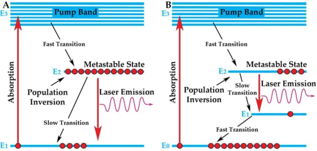
FIGURE 2.2-ENERGY LEVEL DIAGRAM OF A (A) THREE LEVEL SYSTEM AND (B) FOUR LEVEL LASER SYSTEM. ... 10
FIGURE 2.3-TWO PLANE PARALLEL MIRRORS OPTICAL RESONATOR. ... 11
FIGURE 2.4–SOLAR EMISSION SPECTRUM IN SPACE (AM0) AND ON THE EARTH
(AM1.5)[22];ND:YAG ABSORPTION SPECTRUM [21]. ... 12
FIGURE 3.1-ZEMAXTM NON-SEQUENTIAL OBJECTS MODELLING A PARABOLIC
REFLECTIVE RING SOLAR SYSTEM. ... 14
FIGURE 3.2-SOURCE OBJECTS IN ZEMAXTM ... 16
FIGURE 3.3-LIST OF THE MOST RELEVANT PARAMETERS OF THE SOURCE ELLIPSE FOR THE SOLAR PUMPING SOURCE IN THE NON-SEQUENTIAL COMPONENT
EDITOR ... 16 FIGURE 3.4-DIFFERENT MATERIALS IN THE NON-SEQUENTIAL COMPONENT
EDITOR. ... 17
FIGURE 3.5-ZEMAXTMGLASS CATALOG ... 18
FIGURE 3.6-ZEMAXTM LASER HEAD DESIGN OPTIMIZATION.CONCENTRATED LIGHT RAYS IN BLUE. ... 19
vi FIGURE 3.7-NUMERICAL SIMULATION THROUGH THE VOLUMETRIC DETECTOR IN
ZEMAXTM, SHOWING THE ABSORBED PUMP FLUX DISTRIBUTION ALONG FOUR
TRANSVERSAL CROSS-SECTIONS AND ONE CENTRAL LONGITUDINAL CROSS
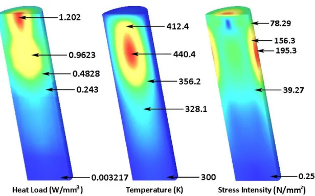
-SECTION OF AN END-SIDE PUMPED ND:YAG ROD BY THE MODIFIED RING -ARRAY CONCENTRATOR. ... 20 FIGURE 3.8- HEAT LOAD, TEMPERATURE AND STRESS INTENSITY DISTRIBUTIONS,
NUMERICALLY CALCULATED IN LASCADTM FOR A 5.5 MM DIAMETER AND 20 MM LENGTH ND:YAG ROD BOTH PUMPED BY THE MODIFIED RING-ARRAY CONCENTRATOR. ... 21
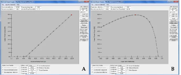
FIGURE 3.9-LASCADTM FINITE ELEMENT ANALYSIS WINDOWS, SHOWING IN "A" A
NUMERICALLY CALCULATED LASER OUTPUT POWER AS FUNCTION OF THE ABSORBED PUMP POWER AND IN "B" A NUMERICALLY CALCULATED LASER OUTPUT POWER AS FUNCTION OF THE OUTPUT COUPLER REFLECTIVITY.BOTH FOR A 5.5 MM DIAMETER AND 20 MM LENGTH ND:YAG ROD PUMPED BY THE MODIFIED RING-ARRAY CONCENTRATOR. ... 22
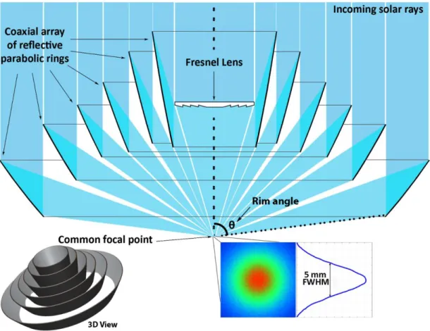
FIGURE 4.1-LONGITUDINAL CUT OF THE SIX PARABOLIC REFLECTORS RING-ARRAY WITH A SMALL FRESNEL LENS.PUMP LIGHT DISTRIBUTION AT THE COMMON FOCAL POINT HAS 5.0 MM FWHM DIAMETER. ... 24
FIGURE 4.2–(A)SIDE VIEW AND (B) TOP VIEW OF THE MODIFIED RING-ARRAY CONCENTRATOR. ... 25
FIGURE 4.3-REFLECTIVITY OF SOME COMMON METALS VERSUS WAVELENGTH AT NORMAL INCIDENCE. ... 26
FIGURE 5.1-5.0 MM DIAMETER,20 MM LENGTH ND:YAG ROD ASSEMBLED WITHIN THE ASPHERIC FUSED SILICA CONCENTRATOR.ND:YAG SOLAR PUMP LIGHT ABSORPTION,1064 NM LASER EMISSION AND WATER-COOLING SCHEMES ARE ILLUSTRATED. ... 28 FIGURE 6.1-NUMERICALLY CALCULATED SOLAR LASER OUTPUT POWER AND THEIR
SLOPE EFFICIENCIES AS FUNCTION OF INCOMING SOLAR POWER FOR BOTH 5.0 MM AND 5.5 MM DIAMETER RODS AS 90%,94% AND 98% OUTPUT COUPLER REFLECTIVITIES. ... 32
vii FIGURE 6.2-NUMERICALLY CALCULATED LASER OUTPUT POWER AS FUNCTION OF
THE RIM ANGLE. ... 33
FIGURE 6.3-NUMERICALLY CALCULATED LASER OUTPUT POWER AS FUNCTION OF THE NUMBER OF RINGS IN THE ASSEMBLY. ... 34
FIGURE 6.4-NUMERICALLY CALCULATED LASER OUTPUT POWER AS FUNCTION OF THE ROD DIAMETER. ... 34
FIGURE 6.5-NUMERICALLY CALCULATED TRACKING ERRORS FOR (A) THE RING -ARRAY ASSEMBLY AND (B) THE FRESNEL PUMPING SCHEME WITH THE SAME DIAMETER. ... 36
FIGURE 7.1-NUMERICALLY CALCULATED HEAT LOAD, TEMPERATURE AND STRESS
INTENSITY FOR (A)5.0 MM DIAMETER ND:YAG ROD AND (B)5.5 MM
DIAMETER ND:YAG ROD... 38 FIGURE 7.2-NUMERICALLY CALCULATED LASER OUTPUT AND THERMAL
PERFORMANCE COMPARISON CHART FOR THE 5.0 MM AND 5.5 MM DIAMETER
ND:YAG RODS. ... 39
FIGURE 8.1-RING-ARRAY 1:7 SCALE MODEL FIRST PROTOTYPE RING DISPLACEMENT AND FOCUSING ADJUSTMENTS. ... 43 FIGURE 8.2-SIX SILVERY-COATED 3D PRINTED PLA PARABOLIC RINGS AND
STRUCTURE FOR RING FIXATION. ... 44 FIGURE 8.3-ZEMAXTM SHADED MODEL OF THE RING-ARRAY AND THE 80 MM
LENGTH,10 X 5 MM RECTANGULAR SECTION FUSED SILICA LIGHT GUIDE.BLUE LINES INDICATE THE INCOMING SOLAR RAYS (100 DISPLAYED), GREEN FOR FIRST REFLECTION RAYS, YELLOW FOR SECOND REFLECTIONS AND THE OTHER COLOURS REPRESENT THE RAYS AT THE OUTPUT OF THE LIGHT GUIDE. ... 45 FIGURE 8.4-ZEMAXTM SHADED MODEL OF THE RING-ARRAY AND THE CONICAL
REFLECTOR.BLUE LINES INDICATE THE INCOMING SOLAR RAYS (100
DISPLAYED), GREEN, YELLOW AND RED INDICATES REFLECTED AND RE
-REFLECTED RAYS. ... 46
FIGURE 8.5-LIGHT LEAKS INTO THE BACK OF THE RINGS;LIGHT DISPERSION AT THE FOCUS SHOWN IN A PIECE OF PAPER IN COMPARISON TO THE ZEMAXTM SIMULATED FOCUS DIAMETER. ... 47
viii FIGURE 8.6–CONCENTRATION SOLAR POWER TESTING WITH THE 1:7 SCALE MODEL
ASSEMBLY IN A TRIPOD MOUNT SPECIALLY DESIGNED AND SETTLED FOR THIS PURPOSE. ... 48 FIGURE 8.7-SOLIDWORKSTM RENDERED VIEW OF THE ASSEMBLED AND
EXPLODED RENDERED VIEWS OF THE LASER HEAD, SHOWING THE ASPHERIC FUSED SILICA, THE 5.0 MM DIAMETER AND 20 MM LENGTH ND:YAG ROD, THE SILVERY-COATED PUMP CAVITY, TWO O-RINGS, AND THE BASE WITH THE COOLING CHANNELS. ... 49
FIGURE 8.8-SOLIDWORKSTM RENDERED VIEW OF SIX PARABOLIC RINGS WITH FASTENINGS. ... 50
FIGURE 8.9-RING ARRAY ASSEMBLY IN:(A) ITS WORK POSITION AND (B) ITS REST POSITION... 51 FIGURE 8.10-SOLIDWORKSTMRENDERED VIEW OF THE 404 MM BAR AND THE
ISO-4034-M16-S NUT. ... 51
FIGURE 8.11-SOLIDWORKSTMRENDERED VIEW OF THE 162 MM M16 THREADED
ROD, THE STEPPER AND THE LINK BETWEEN THEM. ... 52
FIGURE 8.12-SOLIDWORKSTM RENDERED FINAL ASSEMBLY PROTOTYPES OF THE
MODIFIED RING-ARRAY AND AMPLIFIED VIEW OF THE LASER HEAD. ... 53
FIGURE 9.1-SOLIDWORKSTM RENDERED FINAL ASSEMBLY OF A MODIFIED RING
ix
List of Tables:
TABLE 1-RADIUS OF CURVATURE, MAXIMUM AND MINIMUM APERTURE FOR THE SIX RINGS. ... 25
TABLE 2-ANALYTICALLY CALCULATED SOLAR LASER OUTPUT POWER, SLOPE
EFFICIENCY AND THRESHOLD PUMP POWER FOR 5.0 MM AND 5.5 MM DIAMETER RODS AT 90%,94% AND 98% OUTPUT MIRROR REFLECTIVITY. ... 31 TABLE 3-CONCENTRATION POWER RESULTS FOR THE LIGHT GUIDE AND FOR THE
HOLLOW CONICAL REFLECTOR. ... 47
TABLE 4-THE RESULTS ATTAINED IN THIS PROJECT COMPARED TO THAT BY BOTH
1
Introduction
Sun-powered lasers are highly desirable in providing cost-effective coherent laser radiation in an environmentally friendly way, especially in places where the Sun is abundant and other energy sources are scarce. Therefore, achieving narrow-band solar laser radiation through its direct conversion from broad-band sunlight with high efficiency is a major goal for many laser applications such as deep space communications, atmospheric and ocean sensing, high temperature materials processing and magnesium-hydrogen energy cycle[1]. For the last fifty years, several researchers [2–7], starting with Young in 1966 [2], have used parabolic mirrors to highly concentrate incoming sunlight into a laser medium. In 1984, H. Arashi et al. have successfully obtained 18 W multimode laser emission by pumping a 4 mm diameter, 75 mm length neodymium-doped yttrium aluminium garnet (Nd:YAG) single-crystal rod within a water-cooled flow tube in the focusing spot of a 78.5 m2 parabolic
reflector, achieving 0.23 W/m2 collection efficiency (defined as solar laser power
achieved per unit area of a primary collector) [4]. Later, in 2003, M. Lando et al. increased the solar laser collection efficiency to 6.7 W/m2 by using a primary
parabolic mirror and a secondary compound parabolic concentrator (CPC) to pump a 6 mm diameter, 72 mm length Nd:YAG rod [6]. By using Fresnel lenses for solar laser pumping, significant progresses were achieved in the last twelve years with several pumping methods [8–12]. In 2007, T. Yabe et al. reached a collection efficiency of 18.7 W/m2 by pumping a 3–9 mm diameter and 100 mm
length Chromium (Cr) co-doped Nd:YAG ceramic laser rod through a 1.4 m2
2 Fresnel lens [8]. In 2011, D. Liang and J. Almeida reached 19.3 W/m2 collection
efficiency by pumping a 4 mm diameter, 25 mm length Nd:YAG crystal rod through a 0.64 m2 Fresnel lens, revitalizing the great usefulness of Nd:YAG
medium [9]. One year after, T. Dinh et al. achieved 30.0 W/m2 collection
efficiency by using a 6 mm diameter, 100 mm length Nd:YAG crystal rod pumped through a 4 m2 Fresnel lens [10]. However, only 0.0064 W laser beam
brightness figure of merit, defined as the ratio between laser power and the product of Mx2 and My2 beam quality factors [6], was achieved [10]. In 2017,
D.Liang et al. attained a new record of 31.5 W/m2 solar laser collection efficiency
by end-side-pumping a 4 mm diameter, 35 mm length Nd:YAG through a heliostat–parabolic mirror system in Procédés, Matériaux et Énergie Solaire — Centre National de la Recherche Scientifique (PROMES-CNRS) [13] and in 2018 D.Liang et al.reached a record collection efficiency of 32.5 W/m2, but with a
Cr:Nd:YAG ceramic laser rod [14]. However, with the heliostat–parabolic mirror combination, shadows from laser cavity and its mechanical supporting structure reduces the effective solar energy collection surface area.
The ring-array solar concentrator design concept was introduced by V. Vasylyev and S. Vasylyev. It consists of a set of parabolic reflective rings mounted coaxially to avoid shading effect from either incoming or reflected light among parabolic rings. Its focal spot in the rear side of the collector is created by superposition of rays from the reflective rings [15].
For laser pumping, this configuration allows efficient combination of components, reducing the shadow areas between incoming solar rays and the laser head as compared with the traditional heliostat–parabolic mirror system. The ring-array concentrator proposed in 2018 by R. Matos et al.[16] and B. D. Tibúrcio et al.[17] was an innovative 1500 mm diameter ring-array concentrator with extremely short focal length which can pump efficiently a solar laser head through tight focusing, enabling a compact solar laser design. The ring-array concentrator also has no chromatic aberration along its focal zone, providing higher solar concentration efficiencies as compared with Fresnel lenses. Additionally, as a modified version of the classical ring-array concentrator, a small Fresnel lens was added in the center of the assembly to concentrate the solar rays lost in the original scheme [16], [17].
3 The entire solar laser design, composed by the modified ring-array concentrator, an aspherical fused silica concentrator, a Nd:YAG rod, and a pump cavity were optimized through ZEMAX™ numerical analyses. Both analytical and numerical analyses were made through LASCADTM to ensure the optimized
laser output performances. 67.8 W continuous-wave solar laser power was numerically attained, corresponding to 38.4 W/m2 collection efficiency, 1.22
times more than the previous record [13].
The popular Nd:YAG crystal rod was used in this study, due to its excellent thermal conductivity, high quantum efficiency and tensile strength, making it a good candidate to produce solar laser radiation efficiently. It is also worth noting that the proposed ring-array concentrator solar laser scheme is also valid for pumping other solar laser materials such as Cr:Nd:YAG ceramic medium [8], Nd:Ce:YAG [18], Alexandrite single-crystal media [19]. Composite laser rods such as YAG–Nd:YAG–YAG undoped–doped–undoped, and Nd:YAG grooved rods [20] can all be successfully pumped in the focal zone of the modified ring-array solar concentrator. High solar laser efficiencies can be expected by pumping the above-mentioned laser media by this proposed compact ring-array concentrator solar laser pumping approach.
Based on the previous design and optimization through ZEMAX™ and LASCAD™ numerical analyses, a small 1:7 scale model of the ring-array concentrator was designed in a computer aided design software (CAD), and built as a proof of concept, to confirm the reliability and performance of this concentrator.
5
Fundamental Concepts
Light amplification by stimulated emission of radiation, best known as LASER (acronym), is an optical process of light amplification, based on the quantum effect of stimulated emission. Although, the laser is not only an amplifier, but a generator, composed by an optical resonant cavity capable of coupling emitted light rays, the gain medium, and a power source.
Understanding the notion of stimulated emission is crucial before any advance on comprehending laser emission. Quantum theory predicts that atoms and molecules only have determined discrete levels of energy; then, only certain orbital configurations are allowed for each atom and only certain frequency and vibrational states are permitted for each molecule. Hence, as energy is transferred from a photon to an electron, it receives that amount of energy. Therefore, level transitions are only allowed in quantized, discrete levels, leading to corresponding absorption and emission lines.
As an electron gets excited by a photon, it passes, from a lower energy level to a higher unstable energy level, and then it will decay naturally to a lower unoccupied energy state. This decay results in a spontaneous emission. A photon is emitted with an unpolarised random phase and random direction, but with a wavelength correspondent to the difference of energy between those two energy levels, as given by Planck’s relation:
∆E = E2 − E1 = ℎυ21 (2.1)
6 Where E2 and E1, are the energies of final and initial states respectively, ℎ
for Planck's constant and υ21 stands for the absorbed or emitted photon
frequency.
As an electromagnetic wave with frequency υ21 passes through an atomic
system where an energy transition ℎυ21 occurs, the lower level population
diminishes at a rate that depends on the number of particles on that level N1 and
the radiation density ρ(υ), as shown below.
𝜕𝑁1
𝜕𝑡 = −𝐵12ρ(υ)𝑁1 (2.2)
Where B12 it’s the proportionality constant with dimensions [cm3 /s2 J] and
B12 ρ(υ) is the probability for a transition to occur due to an external field by time
unit.
If an atom reaches its top level (N2) by absorption, that level’s population
drops spontaneously to N1 according to:
𝜕𝑁1
𝜕𝑡 = −𝐴21𝑁2 (2.3)
Where A21 represents the probability for a level N2 atom to decay
spontaneously to N1, per time unit. A21 it’s a proportionality constant with
frequency dimensions [Hz] and represents a transition probability which is directly related with the excited state lifetime. With the decay, a photon is then emitted (spontaneous emission).
When an incoming photon with a known frequency interacts with an excited electron in the atom, causing it to drop to a lower energy level, a new photon is emitted with the same polarization, same phase, frequency and direction as the incoming photon. This process is known as stimulated emission and it’s responsible for laser emission, as represented in Figure 2.1.
7
Figure 2.1 -Absorption, spontaneous emission and stimulated emission.
The transition rate is given by the following relation:
𝜕𝑁2
𝜕𝑡 = −𝐵21ρ(υ21)𝑁2 (2.4)
And depends on B21, which is the proportionality constant with dimensions [cm3 /s2 J] and is also proportional to the radiation density ρ(υ21) only for a very
narrow range of frequencies (2→1 transition ideally).
With this stimulated emission involving two energy levels, optical gain occurs in the atoms all across the gain medium. In normal, relaxed states, lower energy levels are more populated, since electrons are much less stable in excited states then in fundamental ones as predicted by Boltzmann statistics considering only two non-degenerate states of energy, populated by N1 and N2 respectively,
keeping total particles number.
N1 + N2 = Ntotal (2.5)
Per the above conservation equation, and considering both transition rates, it’s easy to find the following thermal equilibrium:
𝜕𝑁1 𝜕𝑡 = −
𝜕𝑁2
8 Thus, 𝜕𝑁1 𝜕𝑡 = − 𝜕𝑁2 𝜕𝑡 = 𝐵21ρ(υ21)𝑁2− 𝐵12ρ(υ12)𝑁1+ 𝐴21𝑁2 (2.7) And then, 𝐵12ρ(υ12)𝑁1 = 𝐵21ρ(υ21)𝑁2+ 𝐴21𝑁2 (2.8)
Where the first term refers to absorption and the second term to spontaneous and stimulated emission.
For a system with N1 and N2 particles, with E1 and E2 energy, g1 and g2
degeneracy respectively, in thermal equilibrium, Boltzmann coefficient shows the N2/N1 ratio as indicated below.
𝑁2 𝑁1= 𝑔2 𝑔1exp [ −(𝐸2−𝐸1) 𝑘𝑇 ] (2.9) And so, ρ(υ21) = ( 𝐴21 𝐵21) (𝑔2 𝑔1)( 𝐵12 𝐵21) exp( ℎυ21 𝑘𝑇 )−1 (2.10)
According to Planck’s law of black-body radiation:
𝐵𝑣(𝑇) = 2ℎυ3 𝑐2 1 𝑒 ℎυ 𝑘𝑇−1 (2.11)
Where, Bv(T) is the spectral radiance (power per unit solid angle and per
9 frequency at thermal equilibrium at temperature T. h is the Planck constant; c, for the speed of light in vacuum; k is the Boltzmann constant; υ is the frequency of the electromagnetic radiation and T is the absolute temperature of the body.
By the Planck’s law of black-body radiation (2.11) and the equation above (2.10), the Einstein coefficients are obtained.
ρ(υ)𝜕υ =8𝜋υ2𝜕υ 𝑐3 ℎυ 𝑒 ℎυ 𝑘𝑇−1 (2.12) Where, 𝐵21 =𝑔1 𝑔2𝐵12 (2.13) And, 𝐴21 = 1 𝜏21 (2.14)
Therefore, amplification is granted by the stimulated emission.
However, to have more gain than absorption, a population inversion is needed, this means, to have more electrons populating upper levels than lower levels. This population inversion is a thermally unbalanced state for any system; in other hand, the population in lower levels is always higher in thermal equilibrium. But, then, a positive gain can never occur.
To occur a laser emission, the presence of a metastable level is needed, as the population inversion mechanism, shown in Figure 2.2 is only favorable through the presence of this level.
Due to the strong coupling of the internal oscillations to the surrounding lattice, most ion transitions show fast non-radiative decays. Radiative decay processes may occur, but normally with short lifetimes and broad linewidths. Only a few transitions of selected ions in solids turn out to be decoupled from
10 the lattice vibrations, which have a radiative decay that leads to relatively long lifetimes. As shown in Figure 2.2, in three or four level laser systems, the transition frequencies from E3 to E2 and E1 to E0 fall within the frequency range
of the vibration spectrum of the host crystal lattice. These transition tend to the relaxed state extremely fast with the emission of a phonon (non-radiative decay) to the lattice vibrations with lifetimes of approximately 10-11 to 10-8 seconds.
However, E3 to E0; E3 to E1; E2 to E0 and E2 to E1 transitions, with larger energy
gaps, are often associated to transition frequencies higher than the highest possible vibration frequency of the crystal lattice. Since phonons at those high frequencies are not accepted by the lattice, these transitions cannot relax via simple-phonon spontaneous emission, but relax either by the emission of a photon or by multiple-phonon emission, which are relatively weak when compared to a single-phonon relaxation process. Consequently, those transitions will have a much slower relaxation rate of approximately 10-5 to 10-3 seconds. The
pump level energy band (E3) will then relax into the metastable level (E2) which
has a long lifetime due to the inexistence of other levels located close below it, into which it could directly decay.
Figure 2.2 - Energy level diagram of a (A) three level system and (B) four level laser system.
Despite being independent from population distribution along the energy levels, absorption and stimulated emission are strongly correlated. As the low-level population decreases, and the high-low-level increases, the stimulated emission
11 process upsurges and the radiation increases while passing by the gain medium. On the other hand, with the decrease of the high-level population, low-level population rises, and the number of absorption transitions will surpass the emission ones which will lower the radiative process. For an equity on population density between both levels, the number of emissions becomes equal to the number of absorptions, and the gain medium becomes transparent to radiation.
In that way, a drastic redistribution of electrons in atomic energy levels is needed to have laser emission. For that, laser pumping in an optical resonator with an appropriate gain medium is required.
Regardless of very high gain exotic media, where amplified stimulated emission delivers substantial power with only one single pass through the gain medium, a laser will always need an optical resonator (laser cavity), typically composed by two or more plane parallel or spherical mirrors arranged in various ways, optically aligned with the gain medium, as shown in Figure 2.3. in which the laser radiation forms standing waves for certain resonance frequencies providing laser feedback and compensating optical losses (round trip losses) by passing through the gain medium multiple times. Those produced standing wave patterns are called modes, which can be transversal or longitudinal; both are frequency dependant, but only transversal mode depends also on the intensity across the cross section of the laser beam.
12 Gas, liquid and solid gain media have all been good candidates for solar lasers. However solid lasers are more suitable because of their inherent high energy density and low pumping threshold.
Among solid-state laser materials the Nd:YAG is the most frequently used. Several other laser media can also be applied, but, their absorption depends on the relation between the emitted spectrum from the source and their absorbed spectrum. This is a major concern to consider while choosing the gain medium to use. As it absorbs typically between 730 nm and 820 nm, and between 520 nm and 600 nm the Nd:YAG is then used in this project since we are using sunlight as a pumping source [21], as shown in Figure 2.4.
Figure 2.4 – Solar emission spectrum in space (AM 0) and on the Earth (AM 1.5) [22]; Nd:YAG absorption spectrum [21].
Due to high quantum efficiency, its excellent characteristic on thermal conductivity and fracture strength, Nd:YAG has been considered the most appropriate material to use under highly concentrated solar radiation [23].
13
Modelling of the ring-array, laser head and
solar laser resonant cavity
Numerical and ray-tracing software is of extremely importance in the design, modelling and optimization of solar concentrators and laser systems. For that purpose, two different tools were used in this work:
The design parameters of the ring-array concentrator and the laser head were firstly optimized through the non-sequential ray-tracing software ZEMAX™.
Laser resonator parameters and the optimization of the laser output power and beam quality were then modelled by LASCADTM laser cavity analysis.
3.1 - Modelling of the ring-array and the laser head (ZEMAXTM)
ZEMAX™ is a tool to model, analyse and assist in the design of optical systems. Being a non-sequential ray-tracing software, the rays are traced in a physically realizable path until an interaction with an object. These non-sequential objects can be divided into three types: sources, in our case representing the Sun by the emission of light rays in a solar pumped scheme; optical elements, in which the emitted rays are reflected, refracted, diffracted, absorbed, etc; and detectors, to define qualitatively and to quantify the
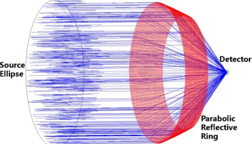
14 information of the incident rays. These three types of non-sequential objects are illustrated in figure 3.1.
Figure 3.1 - ZEMAXTM non-sequential objects modelling a parabolic reflective ring solar system.
3.1.1 - Solar Source
For accurate simulations and truthful results of the solar pumped power by the Nd:YAG rod, several parameters must be taken in consideration, and introduced in ZEMAXTM such as the source power, the number of rays in the
simulation, the emission spectrum and the positioning of the power source. In ZEMAX™ catalogue, numerous parameters are introduced, as solar irradiance of 950 W/m2 in Lisbon (in clear sunny days); inherent Sun–Earth half-angle of ±
0.27º; absorption and dispersion spectra of polymethyl methacrylate (PMMA) material for the Fresnel lens; absorption spectra of silica and water; the peak absorption coefficients and their respective wavelengths for 1.0% Nd3+:YAG laser
medium. Solar irradiance for those absorption peaks were also defined in source wavelength data, according to American Society for Standard and Materials (ASTM) solar spectrum table values at air mass (AM1.5) [24]. The effective pump
15 power for the light source was defined by considering the 16% spectral overlap between the solar emission spectrum and the Nd:YAG absorption spectrum [21]. The number of rays in the analysis will affect the quality of the simulation. A reduced number of rays in the analysis leads to a faster simulation but the accuracy of the results is lower. On the other hand, a very high number of rays produces more accurate results, but with the increase of time spent in each simulation. Therefore, there is an optimum number to be used in each simulation, which can vary from hundreds of thousands for low complexity optical systems, to several million for more complex systems. The optimum number can be obtained by progressively increase the analysis rays until the power absorbed by the detectors, as well as the power distribution, converge.
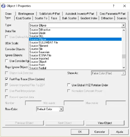
Among several types of source objects, the "Source Ellipse" is the most suitable to define a solar pumping source, this source emits in a cosine distribution of the form in Equation 3.1.
𝐼(𝜃) = 𝐼0(cos 𝜃)𝐶𝑛 (3.1)
Where Cn is the cosine exponent, which can be any value greater than or equal to unity. The larger Cn, the narrower the distribution becomes. The Sun apparent half angle of +- 0.27º must be considered in the ZEMAXTM analysis of
the solar laser system, which is defined by a cosine exponent of 80000. The ZEMAXTM interface of the source objects is shown in Figure 3.2.
16
Figure 3.2 - Source objects in ZEMAXTM
The emission spectrum is defined in the wavelength data editor. When tracing random polychromatic rays, a value of zero for the wavenumber must be defined in the Non-Sequential Component Editor, as shown, among the above-mentioned parameters, in Figure 3.3.
Figure 3.3 - List of the most relevant parameters of the source ellipse for the solar pumping source in the Non-Sequential Component Editor
17 3.1.2 - Optical Elements
Both ring-array concentrator and the laser head were designed using optical elements provided by ZEMAXTM.
Computer aided design software such as SOLIDWORKSTM may also be
used to the design and implementation of some optical elements with inexistent geometries in the ZEMAXTM list of objects. Those SOLIDWORKSTM made objects
can furtherly be exported as stereolithography (.STL) files to ZEMAXTM for the
ray-tracing analysis.
The reflection, refraction or absorption properties of the objects are parameterized according to the material in the editor menu of each non-sequential components, as shown in Figure 3.4.
Figure 3.4 - Different Materials in the Non-Sequential Component Editor.
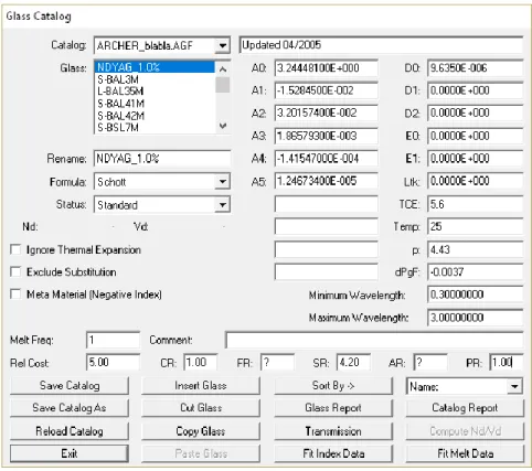
If the object has no reflectivity or refraction, the ABSORB function must be selected in the material column. This function is typically used for detectors or used to create shade in a part we don't want to get into the simulation at a certain point. If the object has reflecting properties, such as each parabolic reflective ring or the internal shape of the laser head, the MIRROR function must be selected. However, in the case of a refractive material, such as the laser rod, the Fresnel lens, or the fused silica aspheric lens, every material property must be defined through the Glass Catalog menu in Figure 3.5.
18
Figure 3.5 - ZEMAXTM Glass Catalog
3.1.3 - Detectors in ZEMAXTM
Detector objects in ZEMAXTM will provide information on incident or
absorbed power from the source. For that purpose, typically two detectors are used: rectangular detector (detector rect) and a volume detector (detector volume). In the present work the former is mainly used to detect the numerical information at the focus of the primary concentrator. This detector can be placed either inside or outside an object, and it can act as a reflector, an absorbent or have no interaction with the incident radiation. The data retrieved by this detector is relatively broad: it detects the incident power and angle, the bidimensional power distribution and the profile of incident and absorbed power in the area defined by the detector. The resolution in this detector is user defined but it has the compromise of a longer simulation time for higher resolutions. The latter one, like the rectangular detector, has the shape of rectangle, but with the possibility
19 to add a new dimension and then become volumetric with a parallelepipedal shape. Leading to power information and data on the incident or absorbed pump power within the laser medium and the pump profile obtention. The resolution of the volume detector is measured by 3D pixels (Voxels). And like the resolution on the rectangular detector, it has a strong impact on the calculation time of each simulation. In ZEMAXTM the volume detector of the laser rod is typically divided
into 18000 voxels. The path length in each voxel is found and with the effective absorption coefficient of 1.0 at.% Nd3+:YAG material, the total absorbed pump
power within the laser rod is numerically calculated by summing up all light that crossed each voxel defined section.
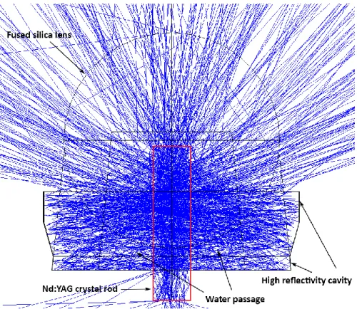
5 million solar rays were simulated. Using ZEMAX™ software, the dimensions of the laser head were optimized to achieve an efficient absorption along the rod. For the aspheric concentrator design, the radius of curvature was firstly optimized. Much design efforts were spent on ensuring the multi-pass absorption by the laser rod within the pump cavity as shown in Figure 3.6.
20 Also, water cooling is a critical issue for optimizing the laser system. Due to its high thermal conductivity, low viscosity and specific heat, water is commonly used to cool the laser rod. A simple water circulation path was designed within the aspheric concentrator. Semi-circular-shaped water entrance and exit apertures of 30 mm2 cross-section were designed in the base to ensure enough
water flow rate of 6 L/min.
Absorbed pump flux distribution through the laser rod and cross sections can be visualized in ZEMAXTM, as shown in Figure 3.7, allowing important
adjustments to be made not only on how the light hits the rod but also on how light scatters and focuses in it, allowing better pumping efficiencies and avoid the rod to break. Stress, temperature and heat load will be studied furthermore with LASCADTM laser cavity analysis.
Figure 3.7 - Numerical simulation through the volumetric detector in ZEMAXTM, showing the absorbed pump flux distribution along four transversal cross-sections and one central longitudinal cross-section of an end-side pumped Nd:YAG rod by the modified ring-array concentrator.
21
3.2 - Modelling of the solar laser resonant cavity (LASCADTM)
After the non-sequential ray-tracing analysis in ZEMAXTM, the generated
files containing the three-dimensional distribution of the absorbed pump power by the active medium are imported to LASCADTM. Through its finite element
analysis, and taking into consideration several laser parameters, such as gain, saturation, reflectivity, radius of curvature and cavity sizes, it is possible to model resonant cavities by analysing the multimode and TEM00-mode output power
and the laser efficiency, the thermal lensing effects, laser beam quality, profile and beam propagation outside the laser cavity. This finite element analysis also generates three dimensional representations of the laser rod heat load, temperature and stress intensity, as shown in Figure 3.8.
Figure 3.8 - Heat load, temperature and stress intensity distributions, numerically calculated in LASCADTM for a 5.5 mm diameter and 20 mm length Nd:YAG rod both pumped by the modified ring-array concentrator.
22 The laser resonator can be optimized by changing its length and angle between its components, by inserting mirrors/lenses or by changing the position of the components. Also, a visualization of the laser emission curve as a function of either the absorbed pump power or the reflectivity of the output coupler is possible, as shown in Figure 3.9.
Figure 3.9 - LASCADTM finite element analysis windows, showing in "A" a numerically calculated laser output power as function of the absorbed pump power and in "B" a
numerically calculated laser output power as function of the output coupler reflectivity. Both for a 5.5 mm diameter and 20 mm length Nd:YAG rod pumped by the modified ring-array concentrator.
23
Modified Ring-Array Assembly
Together with the light refractions by the small 280 mm diameter and 3 mm thickness Fresnel lens, the proposed ring-array concentrator assembly provides a compact solar laser system since it is based on single reflection on each parabolic surface, as indicated in Figure 4.1. Solar rays from each parabolic ring with proper radius superimposes on a single 5.0 mm full width at half maximum (FWHM) diameter near Gaussian focal spot.
To achieve the maximum solar concentration efficiency and to avoid shading effect, the number of rings, the radius and spacing between each concentric ring were optimized by ZEMAX™ optical design software.
24
Figure 4.1 - Longitudinal cut of the six parabolic reflectors ring-array with a small Fresnel lens. Pump light distribution at the common focal point has 5.0 mm FWHM diameter.
In Figure 4.2 is represented the entire assembly of the primary concentrator in two different perspectives and the dimensions for the six ring-array concentrator rings, from the larger one with 1500 mm diameter to the smaller one with a diameter of 280 mm. The ring-array concentrator assembly is 655 mm in height.
25
Figure 4.2 – (A) Side view and (B) top view of the modified ring-array concentrator.
The central small Fresnel lens has 280 mm diameter, 3 mm thickness and 460 mm focal length. Table 1 is showing the key dimensions considered for each of the six rings, the radius of curvature and the maximum and minimum apertures.
Table 1 - Radius of curvature, maximum and minimum aperture for the six rings.
Ring (from large to small) 1 2 3 4 5 6
Radius of curvature (mm) 559 343 220 138 72 34
Max. Aperture (mm) 750 600 480 390 300 218
26 Each ring is 5.0 mm thick and has a 95% reflectivity coating on its parabolic surface. Reflective coatings can be from various materials, metals mostly. Different metals have different reflectivities for the same wavelength. The most appropriate will depend on the absorbance wavelength of the laser media. For Nd:YAG, silver and gold coatings are often considered as preferred coatings for such media, as their reflectivities are high in the same wavelength Nd:YAG absorbance is high. However, silver oxides quickly and gold reflectivity is not at its maximum value between 500 nm and 600 nm where Nd:YAG has some absorption peaks. Therefore, protected silver and aluminium coatings are habitually considered, despite the aluminium dip in its reflectivity in the 700 nm - 900 nm range spectrum.
A chart showing the reflectivity of some common metals versus wavelength at normal incidence [25], is shown in Figure 4.3.
27
Laser head and 1064 nm laser resonant cavity
Both the aspheric fused silica concentrator and the small silvery-coated pump cavity are the most relevant components of the proposed laser head. The entire laser head is 36.5 mm in height and as a diameter of 35.6 mm. The aspheric concentrator and the pump cavity are mechanically fixed on a base where both the laser rod and water-cooling channels are integrated. Figure 5.1 is showing the laser head design, laser rod absorption profile (red colour for near maximum pump absorption and dark blue colour for little or no absorption) and the layout of laser resonant cavity for 1064 nm laser emission.
28
Figure 5.1 - 5.0 mm diameter, 20 mm length Nd:YAG rod assembled within the aspheric fused silica concentrator. Nd:YAG solar pump light absorption, 1064 nm laser emission and water-cooling schemes are illustrated.
Highly concentrated solar rays from the ring-array concentrator are firstly focused by the aspheric concentrator to the laser crystal and then enter the pump cavity which ensures an efficient multi-pass pumping to the rod. For end-pumping, a part of the concentrated radiation is directly focused onto the input end face of the rod which is highly reflective (HR) coated for the laser emission wavelength (HR > 99.8% @ 1064 nm). The output end face has an anti-reflective (AR) coating for the same wavelength (AR < 0.2% @ 1064 nm). The output coupler has a partial reflective (PR) coating also for 1064 nm. The multi-pass side pumping is ensured by the highly reflective pump cavity design as shown in Figure 5.1. The cooling channel with 30 mm2 cross-section ensures an efficient
non turbulent water cooling to the rod. Important dimensions of the laser head are also given in Figure 5.1.
29
Solar laser output power calculation, slope
efficiency and threshold power
In this chapter, both theoretical and numerical analysis are presented concerning the solar laser output power, the slope efficiency and threshold power for 5.0 mm diameter and 5.5 mm diameter Nd:YAG rods.
The dependency of the laser output power on the number of rings, the rim angle of the ring array and rod diameters is also studied through LASCADTM
numerical analyses.
The ring-array assembly tracking error impact on solar laser output power is also numerically calculated and compared with a Fresnel pumping scheme with the same diameter.
6.1 - Theoretical analysis
Laser output power (Pout) is expressed in terms of incoming input power
(Pincoming) and some measurable quantities stated by the following equation Eq.
(6.1) [23]:
30 min
2
1
1
2
ln
OVP T A Q S B out inco g sR
P
P
AI
R
l
R
−
=
−
+
−
(6.1)Where, A stands for the laser rod cross-section area (0.196 cm2 for the 5.0
mm diameter rod and 0.238 cm2 for the 5.5 mm diameter rod), Is refers to the
saturation gain (2.9 kW/cm2) [23], R for the output coupler reflectivity, α for the
laser material scattering coefficient (0.003 cm-1), and l the laser rod length (2.0
cm). 2αl expresses the two-way loss in the resonator cavity, ηOVP is the overlap
between the solar emission spectrum and the laser medium absorption spectrum (0.16 for Nd:YAG) [21]. The portion of useful pump radiation, transferred from the input face of the ring-array concentrator to the laser medium, is given by ηT
which is strongly dependent on concentration optics, pump cavity dimensions as well as their reflection and absorption losses. The portion of the transferred useful radiation absorbed by the laser medium is defined by ηA. ηT = 0.80 and ηA
= 0.84 were found through ZEMAXTM analysis for the 5.0 mm diameter rod and
ηT = 0.83 and ηA = 0.86 for the 5.5 mm diameter rod. ηQ (0.90) [24] stands for
quantum efficiency and ηS is the Stokes factor. For the mean absorbed and
intensity-weighted pump wavelength of 660 nm, ηS = 0.62 was obtained [3]. The
beam overlap efficiency ηB (defined as the spatial overlap between the resonator
modes and the absorbed pump distribution within the laser medium [24]) was numerically calculated in LASCADTM with the result of ηB = 0.91. For the same
input solar radiation and resonator configuration, the product of these efficiencies remains constant if changes are only on the output coupler reflectivities.
The slope efficiency (ηslope) for each reflectivity can be calculated from Eq.
(6.1), as shown in Eq. (6.2) [23]:
2
1
1
2
ln
OVP T A Q S B slopeR
R
l
R
−
=
+
−
(7.2)31
2
ln
2
th s OVP T A Q S Bl
R
P
AI
−
=
(6.3)Three output couplers with different reflectivities (90%, 94% and 98%) were analysed, attaining the highest laser output power by 94% reflectivity, both for 5.0 mm and 5.5 mm diameter rods, as shown in Table 2. The calculation of slope efficiency and threshold pump power was made by applying the above equations for both rods (Table 2).
Table 2 - Analytically calculated solar laser output power, slope efficiency and threshold pump power for 5.0 mm and 5.5 mm diameter rods at 90%, 94% and 98% output mirror reflectivity.
Output coupler reflectivity 90 % 94 % 98 %
5.0 mm diameter
Laser power (W) 62.05 66.80 54.28
Slope efficiency (ηslope (%)) 5.1 4.7 3.5
Threshold power (PTh(W)) 591 372 162
5.5 mm diameter
Laser power (W) 60.69 67.79 56.34
Slope efficiency (ηslope (%)) 5.3 5.0 3.8
Threshold power (PTh(W)) 676 426 186
More accurate laser output powers are calculated through LASCADTM
software in the next section since they involve the detailed absorbed pump power distribution and its associated thermal effects within the laser rod.
6.2 – LASCADTM numerical analysis
For the laser output power and beam quality optimization, the absorbed pump data from ZEMAXTM was processed using LASCADTM software.
32 µs [23]; typical absorption and scattering loss of 0.003 cm-1 for the 1.0 at%
Nd:YAG medium and intensity-weighted solar pump wavelength of 660 nm were all considered in the LASCADTM analysis. As shown in Figure 5.1, the top
face of the rod is high-reflection (HR) coated for the laser emission wavelength of 1064 nm (R > 99.8%) and the bottom end face is anti-reflection (AR) coated for 1064 nm wavelength (R < 0.2%). The output coupler has a partial-reflection (PR) coating at 1064 nm. The optical laser resonator is hence formed by the HR 1064 nm reflector, the laser rod and the PR 1064 nm output coupler which is located 11 mm away from the laser rod bottom AR face. Assuming 90%, 94% and 98% reflectivities, LASCADTM analysis was used to evaluate the laser output power
and their respective slope efficiencies for both rods as function of the incoming solar power as shown in Figure 6.1.
Figure 6.1 - Numerically calculated solar laser output power and their slope efficiencies as function of Incoming solar power for both 5.0 mm and 5.5 mm diameter rods as 90%, 94% and 98% output coupler reflectivities.
LASCADTM numerical results as shown a decent consistency in threshold
power, laser power and slope efficiency when compared to the analytical results shown in Table 2. Its worth noticing that numerically calculated values tend to be more accurate than the analytical ones, since LASCADTM relies in a
non-33 homogeneous light absorption by the laser rod instead of the homogeneous distribution considered by the analytical approach.
Different rim angles of 700, 750, 800, 82.50, 850, 87.50, and 900 (Figure 6.2) were
numerically tested to achieve the maximum solar laser power in both ZEMAXTM
and LASCADTM analyses. As given in Figure 6.2, a strong dependency of laser
power on the rim angle was found and the maximum solar laser power was achieved at 840 rim angle. This rim angle is represented in Chapter 4, Figure 4.1.
Figure 6.2 - Numerically calculated laser output power as function of the rim angle.
For the optimal rim angle of 84º, the laser power dependency on the number of rings, while keeping the collection area, was studied through both ZEMAX™ and LASCADTM analyses, attaining the highest laser output power with a six
34
Figure 6.3 - Numerically calculated laser output power as function of the number of rings in the assembly.
Different rod diameters (4.0, 4.5, 5.0, 5.5, 6.0 and 6.5 mm) within the solar laser head (Figure 5.1) were then analysed for calculating their respective solar laser power at 84º rim angle, as shown in Figure 6.4. The maximum laser output power of 67.8 W was attained with the 5.5 mm diameter and 20 mm length rod.
35 LASCADTM numerical analysis was also carried out to calculate the laser
beam quality factors (M2 factors). Mx2 = My2 = 53 and Mx2 = My2 = 55 were
numerically calculated for the 5.0 mm and 5.5 mm diameter rods, respectively. Respective brightness figure of merit of 0.024 W and 0.022 W were hence obtained.
6.3 – Tracking error influence on solar laser output power.
Tracking errors displaces the focal spot from its optimal position, producing optical misalignments and uneven focal spots with the result of less output laser power. In this work a typical tracking error from 0.05º to 0.20º was studied in either azimuthal and altitude axes. Figure 6.5 shows the laser output power for the 5.0 mm diameter and 20 mm length Nd:YAG rod. At the maximum tracking error of 0.20º in both azimuthal and altitude axes, a power of 50.4 W was achieved, corresponding to 25.7% loss on laser power. For the tracking error of 0.20º in only one of the axes, 58.2 W laser power was attained, corresponding to 14.2% loss. For a high precision solar tracker with only 0.05º accuracy in both axes [26], only 1.8% laser power loss was found, resulting in 66.6 W of output laser power, as indicated in Figure 6.5.
To properly evaluate the tracking error associated to the laser output power, a 1500 mm diameter Fresnel lens was also designed to pump efficiently the same 5.0 mm diameter, 20 mm length Nd:YAG rod. A dielectric totally internally reflecting secondary concentrator was employed to couple the concentrated solar radiation from a focal zone to the Nd:YAG rod within a hollow conical pumping cavity.
The key dimensions of the solar laser head, such as the secondary concentrator and the conical pumping cavity was the 1.5 times scaled version of the previous solar laser design with Fresnel lens as a primary concentrator [9]. 39.3 W continuous wave laser power was numerically attained at the optimized focal length of 1.3 m. 2.3% laser power drop was found for 0.05º deviation and 63.6% loss was found for 0.20º deviation, which were 1.30 and 2.48 times,
36 respectively, larger than that by the modified ring-array system, as shown in Figure 6.5.
It is also worth noting the significant laser power enhancement of 1.73 times when the same Nd:YAG rod is pumped by the 1500 mm diameter modified ring-array concentrator, instead of the 1500 mm diameter Fresnel lens. Therefore, Figure 6.5 shows a very clear advantage of the modified ring-array system in both solar laser output power enhancement and tracking error associated laser power reduction.
Figure 6.5 - Numerically calculated tracking errors for (A) the ring-array assembly and (B) the Fresnel pumping scheme with the same diameter.
37
LASCAD
TMsolar laser thermal performance
analysis
As described in Chapter 2, about 84% of solar radiation is not used for laser emission due to the narrow Nd:YAG absorption spectrum [21], contributing to severe heating of the laser rod. For an end-side pump scheme, such as the one proposed in this work, the uneven light flux distribution along the crystal is a serious thermal issue occurring at the rod’s upper-end region. Worth noting that 200 N/mm2 was considered as the fracture limit according to W. Koechner [23].
A 3D visualization of thermally induced effects (heat load, temperature and stress intensity) was made through a LASCADTM analysis, shown in Figure 7.1.
38
Figure 7.1 - Numerically calculated heat load, temperature and stress Intensity for (A) 5.0 mm diameter Nd:YAG rod and (B) 5.5 mm diameter Nd:YAG rod.
Despite having 1.0 W more laser output power than that of the 5.0 mm diameter rod, the 5.5 mm diameter rod has a more severe maximum stress intensity, by reaching a near fracture value of 195.3 N/mm2, while the 5.0 mm
diameter rod has a more comfortable reduced value of 180.8 N/mm2.
A comparison chart of the solar laser performance of both rods in LASCADTM analysis is shown for better comprehension in Figure 7.2.
39
Figure 7.2 - Numerically calculated laser output and thermal performance comparison chart for the 5.0 mm and 5.5 mm diameter Nd:YAG rods.
Consequently, the 5.0 mm diameter and 20 mm length rod was found to be the most suitable choice for the modified ring-array concentrator innovative solar pumping scheme.
41
Scale model of the ring-array concentrator and
future assemblies. SOLIDWORKS
TMCAD.
When manufacturing is considered, SOLIDWORKSTM can play a very
important role as its technical drawing capabilities allows the implementation of accurate and feasible assemblies.
After the optimization of the solar laser system design in both ZEMAXTM
and LASCADTM, this CAD software was used to design all the mechanical
components to build a 1:7 scale model of the ring-array concentrator. Also, it contributed for a future assembly suggestion.
8.1 - Building the scale model ring-array concentrator.
A simple 1:7 scale model of the ring-array concentrator was built to verify how the primary focusing performs.
Each ring was 3D printed in an ANETTM A8 printer, from the original .STL
ZEMAXTM files, exported to SOLIDWORKSTM CAD for the implementation of
thickness and fastening joints on each ring, and then sent to ULTIMAKER CURATM, a 3D printer "slicer" software that works by slicing the .STL object (each
42 ring in this case) into layers and generating a specific code called g-code to be read by the 3D printer.
After 3D-printing in polylactic acid (PLA) (C3H4O2)n, a biodegradable
thermoplastic derived from renewable resources such as sugarcane, wheat starch or corn, each ring was silvery-coated with an 80% reflectivity aluminium coating foil. This reflectivity was calculated through comparison by first measuring the direct sunlight intensity and secondly by measuring the sunlight intensity reflected by a plane foil of this coating in the same environment. Typical values for the most relevant properties of PLA [27], and reflective coating foil are shown in PLA datasheet and Reflective coating datasheet respectively in Chapter 11 - Annexes, section 11.2 - Material datasheet.
As a proof of concept, the first prototype was fixed over a cork surface to allow instant adjustments on each ring level and position. Light focusing was tested with an 80 mm length, 10x5 mm rectangular section fused silica light guide as shown in Figure 8.1.
43
Figure 8.1 - Ring-array 1:7 scale model first prototype ring displacement and focusing adjustments.
With the purpose of a more stable assembly, a fixation structure was also designed in SOLIDWORKSTM and 3D printed with the same material, merely to
hold all the six rings in a fixed position for the superposition of the previously tuned common focusing spot, and to securely fasten the structure to the tripod, as shown in Figure 8.2. Each ring was fastened to the structure with small steel blades to ensure maximum sturdiness and minimum shadowing.
44
Figure 8.2 - Six silvery-coated 3D printed PLA parabolic rings and structure for ring fixation.
It is also worth noting that the Fresnel lens used in the simulations was not considered in this 1:7 scale model, simply because we are aiming to test how the ring-array performs and not on the Fresnel lens performance. Also, at this scale, the Fresnel lens would have about 40 mm diameter and its contribution to the focus shape or efficiency would be negligible.
8.2 - Scale model ring-array concentrator performance
At this scale, measuring the power in the focal zone it's not a simple task due to the dimension of the assembly and also by its tight focusing design.
The first measurements were made with the 80 mm length, 10 x 5 mm rectangular section fused silica light guide as shown in Figure 8.1.
However, it did not represent the more appropriated method to guide the light from the focusing spot to the detector, since only a power of 2.4 W reached
45 the detector. This is primarily due to the flat shape of the input face of the light guide, where most of incoming rays are reflected rather than refracted and transmitted by the light guide. This effect is clearly represented in a ZEMAXTM
shaded model with ray tracing (Figure 8.3) where yellow traces are representing reflected rays in the top face of the light guide.
Figure 8.3 - ZEMAXTM shaded model of the ring-array and the 80 mm length, 10 x 5 mm rectangular section fused silica light guide. Blue lines indicate the incoming solar rays (100 displayed), green for first reflection rays, yellow for second reflections and the other colours represent the rays at the output of the light guide.
Subsequently, a hollow conical reflector with height of 220 mm, and with input and output diameters of 20 mm and 145 mm respectively, was projected, simulated and developed to properly direct the light from the focusing spot of our 1:7 scale model to the detector.
Unlike the first version with the light guide, this will minimise the power loss in the output, as most of the light will enter the hollow conical reflector seamlessly as shown in Figure 8.4.
46
Figure 8.4 - ZEMAXTM shaded model of the ring-array and the conical reflector. Blue lines indicate the incoming solar rays (100 displayed), green, yellow and red indicates reflected and re-reflected rays.
Numerically, and by considering a measured irradiance of 700 W/m2 in
our NOVA solar facility at the time of the experiment, with the hollow conical reflector known reflectance of 90% and the 80% reflectance of each ring, 7.2 W at the detector should be attained with a proper alignment of the common axis of the six parabolic rings to the Sun.
A power of 7.0 W was reached. The difference between the experimental and numerical results may be explained by the 1.3 mm thickness of each ring and by some light leakages due to irregularities in the reflector foil gluing to the rings. These outflows may justify the 3% power loss when comparing to the theoretical model, where a 6 mm diameter focal spot is predicted. A dispersed uneven 20 mm focal spot was obtained. As shown in Figure 8.5, the light reflects into the back of the rings and also disperses on the focusing spot due to those irregularities.
47
Figure 8.5 - Light leaks into the back of the rings; Light dispersion at the focus shown in a piece of paper in comparison to the ZEMAXTM simulated focus diameter.
Table 3 summarises the concentration power performance, both numerical and experimental, between the light guide and the hollow conical reflector in the 1:7 scale model.
Table 3 - Concentration power results for the light guide and for the hollow conical reflector.
Parameters Numerical results Experimental results
Light guide output power (W) 2.9 2.4
Conical reflector output power (W) 7.2 7.0
The final assembly of the 1:7 scale model in a direct sunlight test with the hollow conical reflector and the detector for the power measurements is shown in Figure 8.6.
48
Figure 8.6 – Concentration solar power testing with the 1:7 scale model assembly in a tripod mount specially designed and settled for this purpose.
![Figure 2.4 – Solar emission spectrum in space (AM 0) and on the Earth (AM 1.5) [22]; Nd:YAG absorption spectrum [21]](https://thumb-eu.123doks.com/thumbv2/123dok_br/19292822.994327/32.892.109.757.443.793/figure-solar-emission-spectrum-space-earth-absorption-spectrum.webp)