Journal of Ultrafine Grained and Nanostructured Materials, Vol. 46, No. 1, 2013, pp. 11-17 11
1 - School of Metallurgy and Materials Engineering, University College of Engineering, University of Tehran, North Kargar, Tehran, P.O. Box 11365-4563, Iran.
2- Department of Materials Engineering, Faculty of Engineering, Shahrekord University, P. O. Box 115, Shahrekord, Iran
Corresponding author:
M. Yeganeh, School of Metallurgy and Materials Engineering, University College of Engineering, University of Tehran, North Kargar, Tehran, P.O. Box 11365-4563, Iran.
Email: [email protected]
Effect of Incorporation of Inhibitor Loaded Mesoporous Silica
on the Corrosion Behavior of Epoxy Coatings
M. Yeganeh1, M. Saremi1, A. Keyvani2
Abstract
In this research, mesoporous silica was applied as the host of corrosion inhibitor (molybdate). The loaded mesoporous silica was dispersed in an epoxy matrix. The composite was then coated on the mild steel plate. Results showed that the corrosion resistance of the scratched epoxy having mesoporous silica loaded by molybdate was better than the one without it or neat epoxy. On the other hand, EDX and FTIR studies showed the release of corrosion inhibitor in the scratched zone. It was due to pH-sensitive release of corrosion inhibitor in the aggressive media. Also, XRD data showed the presence of Mo compounds on the surface of steel.
Keywords: Corrosion Inhibitor; Mesoporous Silica; Polymeric Coatings; FTIR; XRD
1. Introduction
Application of protective polymer coating on metals and alloys is the most conventional technique for their corrosion protection in the corrosive media. However, exposure of these coating to aqueous electrolyte solutions may lead to swelling and formation of conductive paths [1]. Therefore, it is required to apply some complementary addition in the coating to provide long-time protection effect in these systems. For this aim, corrosion inhibitors are loaded to polymer coating to provide additional corrosion protection and hinder corrosion activity in defect zones [1]. However, if the corrosion inhibitors are directly loaded in the coating, harmful interactions between the polymer and inhibitor substances may occur, which in turn results in a declination in inhibition capability or coating degradation [2]. Furthermore, corrosion inhibitors have a great potential to leach and fast consumption of inhibitor occurs [1]. To prevent these problems8q, several approaches based on corrosion inhibitor reservoirs have been recently proposed, which prevent interactions between corrosion inhibitor and matrix. These reservoirs consist
of micro or nanocapsules [3-4], nanotubes [5-6], oxide nanoparticles embedded in a matrix [7], ion exchange substances such as cationic clays [8-9], zeolites [10], and hydroxyapatites [11] or anionic clays such as layered double hydroxides [1-2, 12-13], corrosion inhibitor doped in the conductive polymer [14-16], and layer-by-layer polyelectrolyte shells [17-19]. In these reservoirs, an exchange between corrosion inhibitors and corrosive substances, release of corrosion inhibitors by changing pH at corroding sites, or long-time diffusion might occur.
In this research mesoporous silica was used as a nanocontainer. Mesoporous silica has a hexagonal packing of uniform cylindrical pores with the diameter in the range of 2-50 nm, high surface area (700-1500 m2/g), large pore volume (1cm3/g), high chemical and thermal stability, and easy of functionalization [20].
12 Effect of Incorporation of Inhibitor …
protection of this system in comparison with sol-gel coating. Their work results demonstrated the pH-dependent release of inhibitor from mesoporous silica [21]. In another study conducted by Chen et al. benzotriazole (BTA) was loaded in the hollow mesoporous silica spheres. Their findings showed that there was almost no leakage of BTA from mesoporous silica in neutral solution, while in alkaline solution BTA released very quickly, and the release rate rises with increasing in pH values [22]. However, they did not apply these nanocontainers to any coatings.
In this work we have used functionalized mesoporous silica as nanocontainer of molybdate corrosion inhibitor ions and then immobilize it in the epoxy coating. Functionalized mesoporous silica loaded by positive ions could act as anion adsorbent. The adsorption of anionic species (molybdate ions) to functionalized mesoporous silica occurs via electrostatic forces. Therefore, it is expected molybdate anions could release in corrosive media. In this research, the effect of mesoporous silica loaded by inhibitor was examined on the corrosion behavior of mild steel in the epoxy coatings. To prove effectiveness of the inhibitor containing coatings, mesoporous silica without any adsorbed inhibitor was loaded in the epoxy coatings and the corrosion properties were compared with the case of using the adsorbed inhibitor.
2. Experimental
Mesoporous silica powders were synthesized by mixing surfactant molecules such as hexadecyltrimethylammonium bromide (CTAB) and a silica precursor (tetraethylorthosilicate, TEOS) as reported elsewhere [23]. Then initial mesoporous silica was functionalized by silane group (1-(2-aminoethyl)-3aminopropyltrimethoxysilane) and then Fe+3 was incorporated in the functionalized mesoporous silica in the propanol solution at ambient temperature for 3 h. The obtained powder from filtration and washing is denoted as C. Finally, the corrosion inhibitor adsorption was carried out.
The experimental loading was around one-third of the maximum, because of occupied surface of mesoporous silica by functionalized groups. The obtained material is denoted as D.
The size of mesoporous silica pores was analyzed by a transmission electron microscope (TEM Tecnai G2 F30 at 300 kV). The specific surface area, average pore diameter and pore volume were obtained from N2 adsorption–desorption isotherms
(BELSORP mini-II). The specific surface area was calculated from the adsorption data in the low-pressure range by using the Brunauer–Emmett–Teller (BET) method. The average pore diameter and the pore volume were determined from the N2 desorption
branch of the nitrogen isotherms by the Barret–Joyner–Halenda (BJH) method.
Release of corrosion inhibitor from functionalized mesoporous was performed at different pHs in strong acidic, strong basic and near neutral pH. For this aim, 0.05 g powders were submerged in the solutions, which their pH was 1, 5.9, 6.4, 7.5, 8 and 14. The amount of molybdate release after 3 days was characterized by inductively coupled plasma optical emission spectrometry (ICP-OES) model Varian VISTA-MPX. Furthermore, zeta potentials were measured at these pHs using a Malvern Zetasizer.
M. Yeganeh, M. Saremi, A. Keyvani 13
For corrosion tests, a solution with 0.05 M concentration NaCl (Merck) were prepared The electrochemical measurements were carried out in a classical electrochemical cell with a steel plate coated with epoxy, epoxy-loaded mesoporous silica with molybdate composite and epoxy-unloaded mesoporous silica composite as working electrode with an exposed area of 1 cm2. Also in these corrosion tests, the surfaces of coatings were scratched. A Pt plate served as the counter electrode, while a Saturated Calomel Electrode (SCE) was taken as a reference electrode. EIS measurements were conducted at OCP in the range of 100 kHz to 0.01 Hz using a 1260 Solarton frequency response analyzer (FRA). The ZView2 software was used to analyze the EIS data. All electrochemical tests were performed at least three times to ensure data output accuracy.
The Fourier transform infrared (FT-IR) spectroscopic analysis for the coatings was performed by Nicolet IR 100 using KBr disc. The scanning was ranged from 2000 cm-1 to 500 cm-1. X-ray diffraction (XRD) patterns
were recorded with a Philips X’Pert MPD diffractometer using Cu Ka radiation (40 kV, 40 mA) in the range of 20–80°, 0.1° step size and scan rate of 0.05°S-1. The EDX profile of scratched surface was investigated by high resolution scanning electron microscope (SEM Hitachi SU8040, 40 kV).
3. Result and Discussion
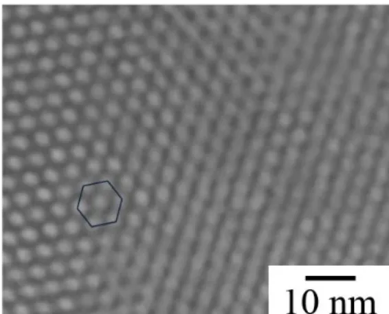
Fig. 1 presents the TEM morphology of mesoporous silica with hexagonal pores. The
average diameter pore, which was obtained by TEM, was about 4 nm. Specific surface area, pore volume, and average pore diameter and of the mesoporous silica was obtained 776.2 m2.g-1, 0.84 cm3.g-1, and 4.33 nm,
respectively. On the other hand, these variations for inhibitor loaded functionalized mesoporous silica were gained 460.5 m2.g-1,
0.48 cm3.g-1, and 3.1 nm, respectively. Specific surface area, pore volume and pore diameter size decreased after functionalization and adsorption of molybdate ions on the surface of mesoporous silica.
The release content of molybdate in various pHs 1, 5.9, 6.4, 7.5, 8 and 14 was obtained 0.86, 57, 91, 98,105, and 320 ppm, respectively. The amount of molybdate release in the alkaline ambient was very higher than acidic ambient. It was probably due to surface potential of powders in the solution. Zeta potentials of samples in various pHs 1, 5.9, 6.4, 7.5, 8 and 14 obtained 38.5, 18.63, 8.54, and -44.3 mV, respectively. Zeta potential was decreased by increasing pH. At pH values different from neutral, silica mesoporous particles and inhibitor ions had the same charge. This led to larger electrostatic repulsion forces and faster release. The mesoporous silica particles at alkaline pH probably contained negative charge. Therefore, it could help electrostatic repulsion forces between the silica mesoporous and molybdate ions and faster release in these ambient. In the acidic ambient, mesoporous silica and molybdate ion had the opposite charge. Accordingly, the attraction between them caused lower release [21]. At acidic pH, zeta potentials were more positive, which means the higher attraction between mesoporous silica and molybdate ions. Therefore, the release in acidic media was lower than alkaline media.
In addition to, the polymerization of molybdate species begins below pH 6 by the formation of heptamolybdate (Mo7O246-) species according to the Eq. 1[24]:
7[MoO4]2- + 8H+ → [Mo7O24]6- +
4H2O
(1)
14 Effect of Incorporation of Inhibitor …
Therefore, the release property of molybdate from mesoporous silica in the acidic pH was lowered due to the formation of polymolybdate species [24]. Larger polymeric molybdate species may precipitate on the mesoporous silica powders and did not participate completely in the solution. Therefore, the amount of molybdate in the solution became lower in comparison with higher pH.
Thus, applying the mesoporous silica nanocarrier to react with OH¯ ions is a good method to diminish cathodic reaction in the near neutral media. Thus, the rate of anodic reaction and total corrosion rate is decreased. In these solutions, the probable cathodic reaction is the reduction of oxygen to hydroxyl as shown in the Eq. 2:
O2+4H2O+4e¯ → 4OH¯ (2)
As the OH¯ ions form in the cathodic sites, the reaction with mesoporous silica nanocarrier occurs and therefore, the content of OH¯ ions is decreased. Thus, a release of the corrosion inhibitor in response to a pH changes in these environment is expected without the need for an additional polyelectrolyte shell systems, which were studied in the literatures [17-19]. Therefore, the near neutral environment for testing corrosion response of mesoporous silica is a good choice. On the other hand, the molybdate has the better performances in these media (pH>6). In addition to, the higher release of molybdate at alkaline media may cause negative effect on the corrosion protection. Therefore, pH=6.4 (0.05 M NaCl) was chosen for the corrosion tests.
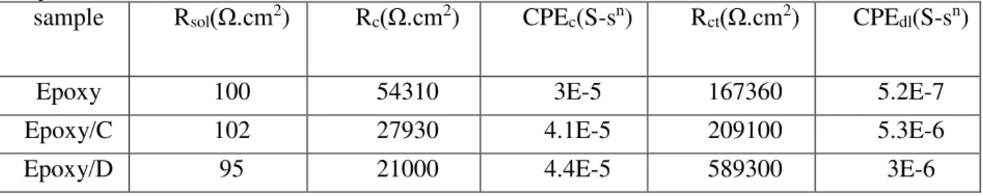
Fig. 2 presents the EIS spectrum of
scratched samples in the 0.05 M NaCl (pH=6.4). Fig. 3 illustrates the corresponding equivalent circuit for impedance plots. The simulated data obtained by ZView2 is listed in Table 1. In this table, Rsol and Rct are the
solution and charge transfer resistance, respectively. CPEdl was used instead of a pure
capacitance accounting for a non-ideal capacitive response of the interface [25]. Rc
and CPEc are related to coatings resistance
and capacitance.
CPEdl is related to electrical double layer
in the solution. Rct is the resistance of faradic
charge transfers in the double layer. The charge transfer resistance, Rct, presents the
corrosion rate of a metal in a corrosive
Fig. 2. EIS plots of Epoxy, Epoxy/ mesoporous silica (C), and Epoxy/ inhibitor loaded mesoporous silica (D) in the 0.05 M NaCl.
Fig. 3. Equivalent circuit for EIS plots
Table 1. Data obtained by ZView2 simulation for epoxy, epoxy/mesoporous silica (C), and epoxy/inhibitor loaded mesoporous silica (D) in the 0.05 M NaCl
sample Rsol(Ω.cm2) Rc(Ω.cm2) CPEc(S-sn) Rct(Ω.cm2) CPEdl(S-sn)
M. Yeganeh, M. Saremi, A. Keyvani 15
ambient. The larger Rct of a material is a sign
of the slower the corrosion rate [25].
The total impedance values measured in the low frequency range can be used to assess the corrosion resistance of the coatings. As seen in Table 1, Rct for the sample containing
loaded inhibitor in the mesoporous silica was
589300 Ω.cm2, while it was 209100 and
167360 Ω.cm2 for the samples containing
only mesoporous silica and neat coating, respectively. The higher Rct for sample with
loaded inhibitor in the mesoporous silica could be explained by the release of molybdate on the corrosion zone. The higher Rct of epoxy/mesoporous silica compared to
epoxy coating was related to the barrier property of mesoporous silica.
MoO42- can react with Fe+2 to form a
protective film when molybdate was loaded in the mesoporous silica according to the Eq. 3 [26-27]:
Fe+2 + MoO42-→ [Fe+2…. MoO42-] (3)
Furthermore, the reacted molybdate with protons will be coordinated with water molecules to form MoO(OH)5-. In the next
step, these species could polymerize to organize an oxygen-bridge ion as Eq. 4[26-27]:
2MoO(OH)5¯ → [(OH)4
OMo-O-MoO(HO)4]2- + H2O
(4)
[(OH)4OMo-O-MoO(HO)4]2- ions react
with the empty orbit d of Fe in the steel to form a complex [26-27]. Then, these complexes are adsorbed on steel surface and disrupt charge transfer and inhibit corrosion reaction. This led to higher corrosion resistance of epoxy/inhibitor loaded mesoporous silica compared to epoxy/mesoporous silica as shown in Table 1. Rc for Epoxy/D had the lowest value, which
could be related to the presence of inhibitor loaded mesoporous silica. In this case, corrosion inhibitor could reduce coating resistance due to its charge. On the other hand, Rc of Epoxy/C and Epoxy/D was lower
than Epoxy. It could be due to the sensitivity
of interfacial region (between mesoporous particles and coating) to ion and water adsorption, which helps to reduce Rc.
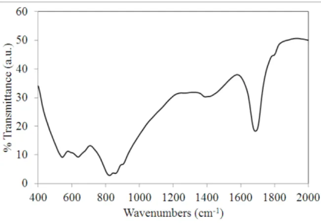
Fig. 4 illustrates FTIR results from the surface of steel coated Epoxy/MSInh after corrosion in the 0.05 M NaCl. The adsorption bands at 894, 809, and 578 cm-1 may be associated to the Mo=O and Mo–O stretching in [Fe2+…. MoO4 2-] or [(HO)4OMo–O–
MoO(OH)4]2- due to corrosion of steel in the
presence of released molybdate. The peaks about 1373 and 1673 cm-1 are associated with
the vibration mode of the Mo–OH bond and the bending mode of adsorbed water, respectively [26]. This is an indication about molybdate ion release from inhibitor loaded mesoporous silica and the formation of bonds with steel.
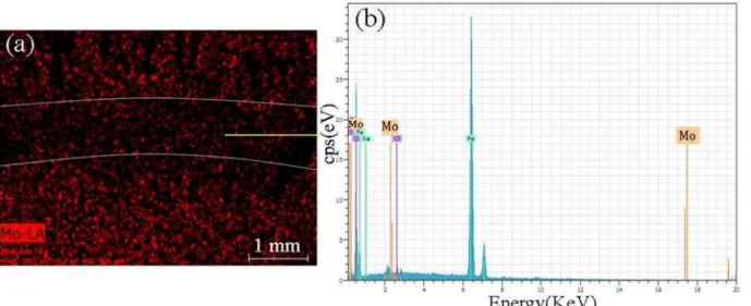
Fig. 5a shows the Mo map of the scratched surface after 72 h. As seen in this map, the Mo (from molybdate) could release from the epoxy and distribute on the scratched zone. This shows the ability of mesoporous silica to release corrosion inhibitor in the corrosion sites. Fig. 5b shows the Energy Dispersive X-Ray Analysis (EDX) plot of corroded area. There were Mo peaks in the corroded area, which is a proof of releasing and adsorbing molybdate on the steel surface. This indicates the adsorption and reaction of Molybdate anions on the carbon steel surface and formation of a protective layer.
Furthermore, XRD analysis of scratched zone showed the presence of MoO3 and Fe2
(MoO4)3, which is a sign of molybdate
reaction with steel (Fig. 6).
16 Effect of Incorporation of Inhibitor …
4. Conclusions
In this research, the effect of loading a corrosion inhibitor in the mesoporous silica was studied. PH-sensitive release of molybdate from functionalized mesoporous silica observed. Molybdate release at alkaline media had the highest value, while it had the lowest at acidic media. Corrosion inhibition of this system was studied in the near neutral media. Epoxy coating which had the inhibitor loaded in the mesoporous silica had the highest corrosion resistance in the 0.05 M NaCl. Results showed that the molybdate could release in the artificial scratch on the epoxy coating. In addition to, charge transfer resistance of this coating had the highest value in comparison with the other samples. It was due to adsorption of released molybdate
from mesoporous silica on the scratched surface.
Acknowledgement
The financial support provided by Chaharmahal and Bakhtiary Province Gas Company is gratefully acknowledged.
References
1. Zheludkevich, M.L., Poznyak S.K., Rodrigues, L.M., Raps, D., Hack, T., Dick, L.F., Nunes, T., Ferreira, M.G.S., (2010), Corrosion Science, 52 (2), 602–611.
2. Tedim, J., Poznyak, S. K., Kuznetsova, A., Raps, D., Hack, T., Zheludkevich M. L., Ferreira, M. G. S., (2010), ACS Applied. Material & Interface. 2 (5), 1528-1535. 3. Khramov, A. N., Voevodin, N. N., Balbyshev,
V. N., Mantz, R. A., (2005), Thin Solid Films, 483 (1-2), 191-196.
4. Khramov, A. N., Voevodin, N. N., Balbyshev V. N., Donley, M. S., (2004), Thin Solid Films, 447 (1), 549-557.
5. Abdullayev, E., Lvov, Y., (2010), Journal of Material Chemistry, 20, 6681–6687.
6. Lvov, Y. M., Shchukin, D. G., Möhwald, H., Price, R. R., (2008), ACSNano, 2 (5), 814-820.
7. Zheludkevich, M. L., Serra, R., Montemor, M. F., Yasakau, K. A., Salvado, I. M., Ferreira, M. G. S., (2005), Electrochimica Acta, 51 (2), 208-217.
8. Williams, G., Geary, S., McMurray, H.N., (2012), Corrosion Science, 57 (4), 139–147. Fig. 6. XRD pattern of scratched zone on the surface of
epoxy/inhibitor loaded mesoporous silica in 0.05 M NaCl
M. Yeganeh, M. Saremi, A. Keyvani 17
9. Williams, G., McMurray, H.N., Loveridge, M.J., (2010), Electrochimica Acta, 55 (5), 1740–1748.
10. Deya´, C., Romagnoli, R., del Amo, B., (2007), Journal of Coating Technology and Research, 4 (2), 167–175.
11. Snihirova, D., Lamaka, S. V., Taryba, M., Salak, A. N., Kallip, S., Zheludkevich, M. L., Ferreira, M. G. S., Montemor, M. F., (2010), ACS Applied Material & Interface, 2 (11), 3011–3022.
12. Buchheit, R. G., Guan, H., Mahajanam S., Wong, F., (2003), Progress in Organic Coatings, 47 (3-4), 174–182.
13. Mahajanam, S.P.V., Buchheit, R.G., (2008), CORROSION, 64 (3), 230-240.
14. Rammelt, U., Duc, L. M., Plieth, W., (2005), Journal of Applied Electrochemistry, 35 (12), 1225–1230.
15. Paliwoda-Porebska, G., Rohwerder, M., Stratmann, M., Rammelt, U., Duc, L. M., Plieth, W., (2006), Journal of Solid State Electrochemistry 10 (9) 730–736.
16. Karpakam, V., Kamaraj, K.,
Sathiyanarayanan, S., Venkatachari, G., Ramu S., (2011), Electrochimica Acta, 56 (5), 2165–2173.
17. Shchukin, D. G., Zheludkevich, M., Yasakau, K., Lamaka, S., Ferreira, M. G. S.,
Möhwald, H., (2006), Advanced Materials, 18 (13), 1672–1678.
18. Andreeva, D. V., Skorb, E. V., Shchukin, D. G., (2010), ACS Applie Material & Interface, 2 (7), 1954–1962.
19. Zheludkevich, M. L., Shchukin, D. G., Yasakau, K. A., Möhwald, H., Ferreira, M. G. S., (2007), Chemistry of Materials, 19 (3), 402-411.
20. Walczak, V. M., (2007), Ruhr-Universität Bochum.
21. Borisova, D., Mohwald H., Shchukin D. G., (2011), ACSNano. 5 (3) 1939-1946.
22. Chen, T., Fu J. J., (2012), Nanotechnology, 23, 235605 (8pp).
23. Fryxell, G. E., Cao, G., (2007), Imperial College Press.
24. Zhao, J.M., Zuo, Y., (2002), Corrosion Science, 44 (9), 2119-2130
25. Mackdonald, J.R., (1987), John Wiley & Sons.
26. Qu, Q., Li, L., Jiang, S., Bai, W., Ding Z., (2009), Journal of Applied Electrochemistry, 39 (2), 569-576.