Luciane Macedo de Menezes1, Fabiane Azeredo2, André Weissheimer3,
Juliana Lindemann Rizzato4, Susana Maria Deon Rizzatto5
Cone-Beam computed tomography evaluation of maxillary
expansion in twins with cleft lip and palate
Objective: The establishment of normal occlusal relationships in patients with cleft lip and palate using rapid maxil-lary expansion may promote good conditions for future rehabilitation.
Objective: This study describes the clinical case of monozygotic twins with unilateral cleft lip and palate at the age of mixed dentition, who were treated using the same rapid maxillary expansion protocol, but with two different screws (conventional and fan-type expansion screw). Results were evaluated using plaster models, intraoral and extraoral pho-tographs, and Cone-Beam computed tomography (CBCT) scans obtained before the beginning of the treatment, (T1).
Methods: The patients were followed up for 6 months after maxillary expansion, when the same tests requested at T1 were obtained again for review (T2). T1 and T2 results were compared using lateral cephalometric tracings and mea-surements of the intercanine and intermolar distances in the plaster models using a digital caliper.
Results: The two types of expansion screws corrected the transverse discrepancy in patients with cleft lip and palate. The shape of the upper arches improved at 10 days after activation.
Conclusion: CBCT scans provide detailed information about craniofacial, maxillary and mandibular changes result-ing from rapid maxillary expansion. The most adequate screw for each type of malocclusion should be chosen after detailed examination of the dental arches.
Keywords: Palatal expansion. Midpalatal fissure. Cone-Beam computed tomography. Orthodontics.
How to cite this article: Menezes LM, Azeredo F, Weissheimer A, Rizzato JL, Rizzatto SMD. Cone beam computed tomography evaluation of maxillary expansion in twins with cleft lip and palate. Dental Press J Orthod. 2012 Mar-Apr;17(2):42e.1-11.
Submitted: January 01, 2010 - Revised and accepted: January 01, 2011
» The authors report no commercial, proprietary, or financial interest in the products or companies described in this article.
Contact address: Luciane Macedo de Menezes
Av. Ipiranga, 6681 – prédio 06 – CEP: 90.619-900 – Porto Alegre / RS – Brazil Caixa Postal 1429 – E-mail: [email protected]
1 Professor, Orthodontics, School of Dentistry, Pontifícia Universidade Católica do
Rio Grande do Sul (PUCRS), Porto Alegre, Brazil.
2 Graduate student, Specialization in Orthodontics, PUCRS, Porto Alegre, Brazil. 3 Graduate students, Doctorate Program in Orthodontics and Facial Orthopedics,
PUCRS, Porto Alegre, Brazil.
4 Graduate student, Specialization in Orthodontics, PUCRS, Porto Alegre, Brazil. 5 Professor, Orthodontics, School of Dentistry, Pontifícia Universidade Católica do
INTRODUCTION
Cleft lip and palate, a congenital malformation that has important clinical and psychosocial im-pacts,1 may be a single deformity (nonsyndromic origin) or part of a group of multiple congenital anomalies (syndromic origin).11 Its etiology is com-plex and includes genetic and environmental fac-tors.14 Tooth anomalies in number and shape are usually present and may affect primary and per-manent dentition.28 Subjects with a cleft lip often have a deficient maxillary development because of the primary surgeries (cheiloplasty and palato-plasty) performed in the first year of life. The reha-bilitation of patients with cleft lip and palate may be complicated by anterior or posterior cross bite, and facial esthetics9 may be affected due to maxillary retrusion and mandibular prognathism.13 Maxillary hypoplasia in subjects with a cleft palate is often not restricted to the dentoalveolar segment, but also involves the paranasal, infraorbital and zygomatic regions.20 In some cases, the alveolar segments may collapse medially, and maxillary expansion is rec-ommended when the maxillary is very narrow10 to reestablish the harmony of the upper arch.22
The success of maxillary expansion depends on the timing for the use of this technique, which may start during pubertal or prepubertal growth.2 The establishment of normal occlusion in patients with cleft lip and palate at the right time using palatal ex-pansion may ensure optimal conditions for future rehabilitation, reduce tooth impaction, and pro-mote normal growth and maxillary development.25
Several orthodontic devices have been devel-oped for maxillary expansion.4 Some of the most frequently used are the Haas expander and modi-fied appliances that use fan-type expansion screws. The purpose of this screw, as the name suggests, is to expand the anterior region and limit the expan-sion of the posterior region of the maxilla. Patients with a cleft lip and palate and maxillary atresia of-ten require different amounts of expansion in the anterior and posterior segments.16 Therefore, be-fore treatment, details about the suture position and the margins of the dentoalveolar and craniofa-cial structures should be obtained.24
Some of the standard tests for orthodontic di-agnoses are panoramic radiography and lateral
cephalometry, but posteroanterior (PA), occlusal and periapical radiographs may also be useful in cas-es that require maxillary expansion.8 In addition to conventional radiographs, computed tomography (CT) is a diagnostic imaging method that also expos-es patients to radiation, but reproducexpos-es parts of the human body in any of the three spatial planes.6 The introduction of cone beam computed tomography (CBCT) made 3D images available for use in Den-tistry. The advantages of CBCT over conventional CT are low radiation dose, lower cost and high image resolution.15 It is extremely valuable for diagnosis and treatment planning in cases of individuals with a cleft lip and palate because it provides better infor-mation about the appearance and size of the anatom-ic structures affected by the cleft, as well as the posi-tion of adjacent teeth and the airways, for example.
This study describes the clinical case of monozy-gotic twins with cleft lip and palate that underwent rapid maxillary expansion (RME) with two types of expander. The dental and skeletal effects of the treatment were evaluated using CBCT scans.
MATERIAL AND METHODS
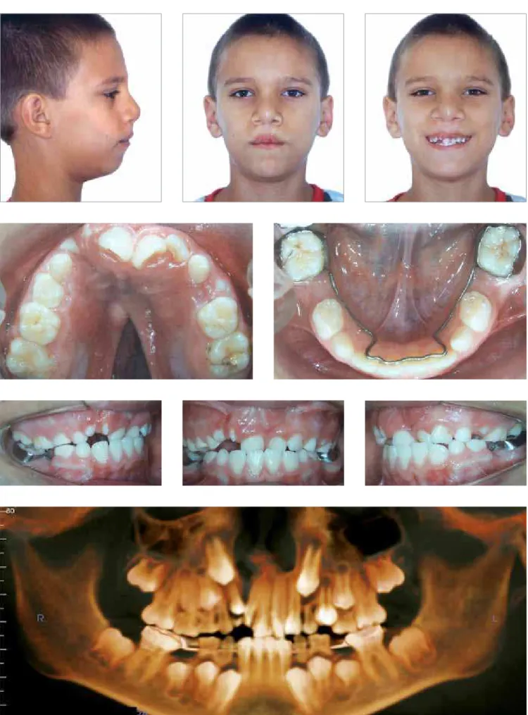
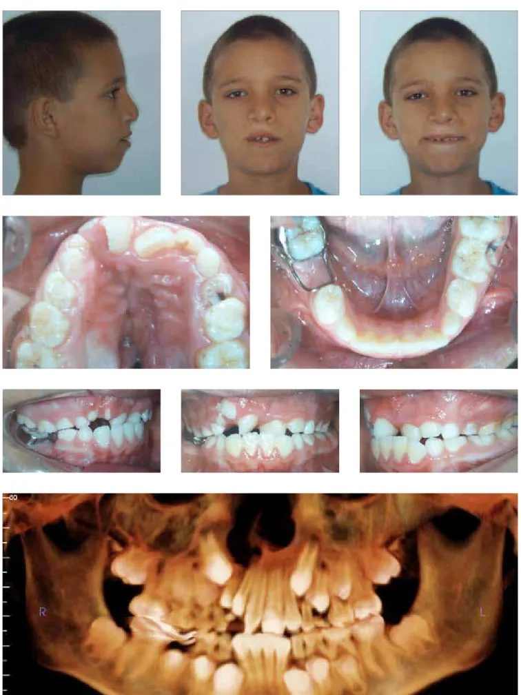
Two 10-year 4-month-old male monozygotic twins at similar skeletal maturation stages, mixed dentition and cleft lip and palate sought orthodontic treat-ment at the Lip and Palate Rehabilitation Center (CERLAP) of the School of Dentistry of Pontifícia Universidade Católica do Rio Grande do Sul (PU-CRS), Porto Alegre, Brazil. During childhood, both underwent palatoplasty and cheiloplasty, but still had a large oronasal fistula in the palatal region. For diagnosis and treatment planning, initial tests (T1) were requested: Intra- and extraoral photo-graphs, plaster models, hand-wrist radiographs and CBCT scans of the face.
Diagnosis and treatment protocol
were retroclined and mesially displaced. The an-terior region had no space for the eruption of per-manent canines, and there was early loss of pri-mary mandibular second molars and consequent supraversion of primary maxillary second molars. Before the beginning of the treatment in the CER-LAP, a lingual archwire had already been placed in the mandibular arch (Fig 1). Cephalometric analy-sis revealed a Class II (ANB = 8º) skeletal pattern characterized by mandibular retrusion (SNB = 75º) and vertical growth (Table 1). The first part of the treatment corrected the transverse maxillary defi-ciency using RME with a tooth-anchored expander and a fan-type expansion screw with maximum ex-pansion of 10 mm and 0.2 mm activation for each 1/4 of a turn (65.05.014, Morelli Ortodontia, Soro-caba, Brazil) (Figs 5 and 8).
Patient B had right unilateral cleft lip and pal-ate, maxillary atresia, symmetric face, no lip com-petence, and a slightly convex profile (Figs 2 and 4). Intraoral examination revealed an Angle Class I molar relation, as well as a transverse maxillary deficiency and posterior and anterior cross bite. The analysis of intercanine and intermolar dis-tances (Table 2) revealed a greater constriction of the maxillary arch in the posterior region. In the area of the cleft, there were two supernumerary teeth; maxillary central incisors were retroclined and mesially displaced. The anterior region had no space for the eruption of permanent canines, and there was early loss of primary right mandibular second molar and consequent slight extrusion of primary maxillary second molar. Before the begin-ning of the treatment at the CERLAP, a band and loop space maintainer had already been placed in the permanent right mandibular molar. Cepha-lometry revealed a Class II (ANB = 7º) skeletal pat-tern due to mandibular deficiency (SNB = 73º), and a predominantly vertical growth pattern (Table 1). This patient underwent RME using a modified Haas appliance with a conventional screw with maximum expansion of 9 mm and 0.2 mm acti-vation for each 1/4 of a turn (65.05.003, Morelli Ortodontia, Sorocaba, Brazil) (Figs 5 and 8).
The expansion protocol was the same for both patients: Initial activation of 0.8 mm (4/4 of a turn), followed by daily activations of 2/4 of a turn in the
morning and 2/4 in the evening, to a total of 8 mm after 10 days. When activation was completed, both expansion screws were stabilized using a 0.25-mm orthodontic chromium-nickel ligature (55.01.210, Morelli Ortodontia, Sorocaba, Brazil), and the area that had the activation orifices was covered with a light-curing composite resin. Patients were regu-larly followed up, and 6 months after the end of the active RME phase, orthodontic review exams were obtained: Intra- and extraoral photographs, study models and CBCT scans (T2).
Lateral cephalometric tracings at T1 and T2 were compared, as well as measurements of the in-tercanine and intermolar distances in the plaster models using a digital caliper (727, Starret Ind. e Com. Ltda, Itu, Brazil).
CT image acquisition and readings
Images were acquired using an i-CAT scanner (Imaging Sciences International, Hatfield, PA, USA) at 8 mA, 120 kV, 40-s exposure time, Full protocol and 0.3-mm voxel resolution. For image acquisition, the patients were sitting, the Frankfort horizontal plane was parallel to the ground and the median sagittal plane was perpendicular to the ground. To keep patients in the right position, the CT scanner headrest and a Velcro tape were used.
Axial slices at 0.3 mm thickness were acquired from volume data and exported as Digital Imaging and Communications in Medicine (DICOM) files to a recordable CD-ROM. The InVivoDental Software (Anatomage, San Jose, CA, USA) and the OsiriX Im-aging Software (3.5.1, Geneva, Switzerland) were used for image visualization and analysis.
RESULTS
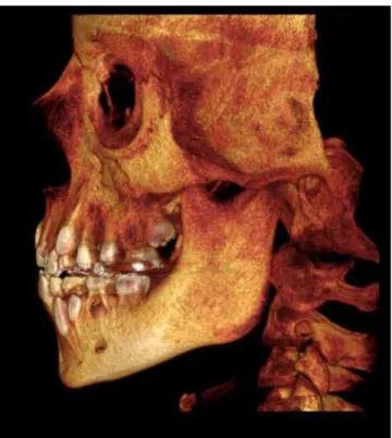
Figure 3 - Frontal and oblique views of three-dimensional reconstruction of face and cranial structures of patient A at T1.
Figure 4 -Frontal and oblique views of three-dimensional reconstruction of face and cranial structures of patient B at T1.
Cephalometric
measures Standard
Patient A Patient B
T1
(9 years) T2
(10 years) T1
(9 years) T2
(10 years)
SNA (degrees) 82° 83° 82° 80° 80°
SNB (degrees) 80° 75° 74° 73° 74°
ANB (degrees) 2° 8° 8° 7° 6°
SND (degrees) 76° 71° 72° 70° 70°
1-NA (mm) 4 -2 -1 0,5 1
1.NA (degrees) 22° -3° 0 13° 15°
1-NB (mm) 4 7 7,5 8 8
1.NB (degrees) 25° 24° 24° 23° 25°
Pg-NB (mm) --- -1 -1 -0.5 -1
1.1 (degrees) 131° 154° 150° 140° 137°
Ocl.SN (degrees) 14° 20° 19° 20° 17°
SN.PP (degrees) --- 12° 10° 13° 10°
SN.GoGn (degrees) 32° 35° 34° 38° 35°
S-UL (mm) 0 3 2.5 3.5 1
S-LL (mm) 0 7 5 7 5
Y axis (degrees) 59° 62° 62° 65° 65°
Facial angle 87.8° 84° 85° 82° 84°
Convexity angle 0° 16° 15° 13° 12°
Wits (mm) --- 3 4 3 5
Table 1 - Summary of cephalometric measurements.
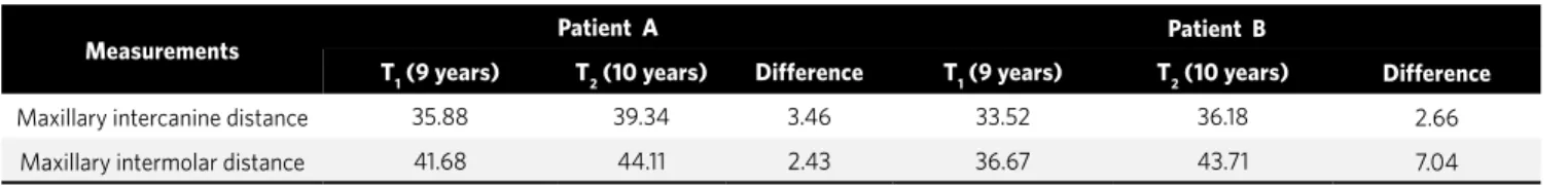
Table 2 - Transverse measures of maxillary arch obtained from study models (in millimeters).
Measurements Patient A Patient B
T1 (9 years) T2 (10 years) Difference T1 (9 years) T2 (10 years) Difference
Maxillary intercanine distance 35.88 39.34 3.46 33.52 36.18 2.66
Maxillary intermolar distance 41.68 44.11 2.43 36.67 43.71 7.04
The examination of facial features revealed that there was a slight change in profile according to the distance of upper and lower lips from the Steiner’s S line and the consequent reduction of the convexi-ty of the lower face (Table 1, Fig 6). In patient B, the skeletal pattern (ANB, SNA, SNB) was preserved in the anteroposterior direction. The comparison of cephalometric tracings at baseline and at 6 months
a b a b
c c
d d
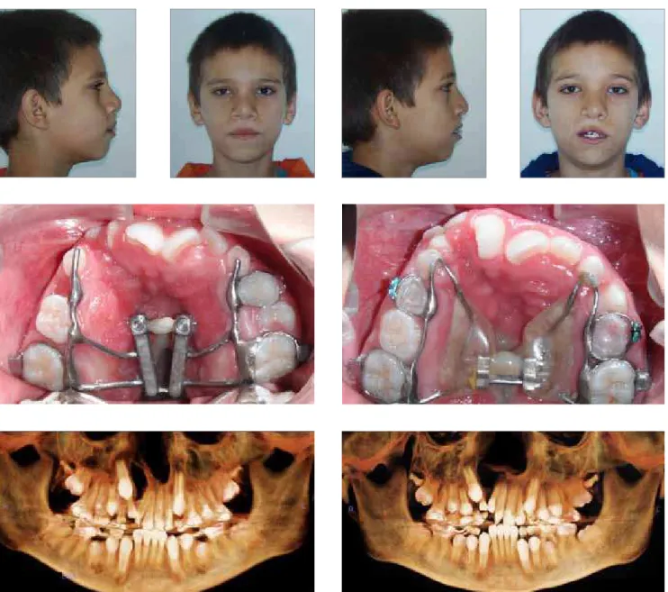
Figure 5 - Extra- and intraoral photographs and panoramic reconstruction of CT images obtained after expansion (patients A and B).
Figure 6 - Total and partial comparisons of lateral cephalometric tracings of patient A at baseline (black) and 6 months after RME (red).
T 1
B
B
T1 T1 T2 T2 T 2A
A
a reduction in the distance of upper and lower lips from the Steiner’s S line and the consequent re-duction of profile convexity (Table 1, Fig 7).
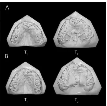
The examination of the maxillary model re-vealed an increase in intercanine distances in rela-tion to intermolar distances for both patients, and a greater increase in the intermolar distance in the patient that received the conventional expander (Table 2, Fig 8).
CT scans showed (Fig 12) the disjunction of frontonasal, frontomaxillary and frontozygomatic sutures, as illustrated in the CT scan obtained for patient B after expansion (T2).
DISCUSSION
This study described the clinical case of mono-zygotic twins with cleft lip and palate and mixed dentition that underwent rapid maxillary expan-sion (RME) with two types of expander. Treatment results were evaluated using CBCT scans.
Three-dimensional images have attracted the interest of dentists because of the difficulties and limitations to obtain diagnostic information using conventional radiographs.6 CBCT was developed in the 90’s as a response to the demands for three-di-mensional information provided by conventional CT scans.12 The introduction of CBCT as a mean to ob-tain images of the maxillofacial region changed para-digms and promoted the transition from a two- to a three-dimensional approach for data acquisition and image reconstruction.23 CBCT produces images of the craniofacial complex at a submillimetric resolu-tion, and scanning times are comparable to those of panoramic radiographs.3 Radiation doses are lower than those of conventional or helicoidal CT and simi-lar to those of other types of dental radiographs.3
This case report showed that RME produced a trans-verse increase of the maxillary arch in both patients, as shown on the CT scans acquired after expansion and in the study models (T2) (Table 2, Figs 5, 8, and 9). The shape of the maxillary arches of both patients im-proved (Figs 5 and 8). The distance between maxillary canines of patient A (appliance with fan-type expan-sion screw) was 0.8 mm greater than in patient B (appli-ance with conventional screw) (3.46 mm vs. 2.66 mm). The main difference between the two patients was the smaller expansion of the intermolar distance in the pa-tient that received the fan-type expander, which lim-ited posterior displacement (Table 2, Figs 8 and 9). Ac-cording to Doruk et al,5 the use of fan-type expansion screws is a rational approach to RME because of the different changes in anterior and posterior transverse distances in the maxilla. Another study showed that frontal cephalometric tracings at baseline, after treat-ment and after retention in a sample of 34 patients with transverse maxillary deficiency revealed an increase in
Figure 8 -Comparison between the initial models (T1) and the models
ob-tained 6 months after the maxillary expansion (T2) in patients A and B.
T
1 T1
B
T2 T2
A
Figure 10 - Frontal and lateral views of three-dimensional reconstruction of cranial structures of patient A at T1 and T2
Figure 11 - Frontal and lateral views of three-dimensional reconstruction of cranial structures of patient B at T1 and T2
the maxillary and nasal cavity widths both in patients treated with fan-type appliances and in the group treated with conventional expanders. However, this in-crease was significantly greater in patients treated with the conventional screw.
Differences in distances in the anterior and posteri-or regions may be affected by the position of the screw. In patient A, the threaded part of the fan-type expan-sion screw was positioned anteriorposteriorly in the re-gion of the maxillary second premolar, that is, at a more anterior position due to its greater volume. In contrast, the threaded part of the conventional screw was posi-tioned anterior-posteriorly in the mesial region of per-manent first molars (Figs 5 and 8).
There seems to be a consensus in the literature about the fact that circum-maxillary sutures are disjointed after rapid maxillary expansion,7,17,27,29 and that RME may affect the intranasal, zygomat-ic-maxillary, nasomaxillary and frontonasal su-tures. 19,21,30 The disjunction of some of the circum-maxillary sutures may be seen in 3D reconstruc-tions at the end of the active RME phase, but not in this study because CT scanning was performed 6 months after RME (Figs 10, 11 and 12).
CONCLUSION
The expansion achieved with the conventional and the fan-type expansion screw corrected the transverse discrepancy in patients with cleft lip and palate and im-proved the shape of the upper arches. Arch shape should be carefully evaluated to choose the screw that will better treat each type of malocclusion. CBCT scans of patients with cleft lip and palate provide detailed visualizations of anatomic structures in this type of deformity, such as the cleft area and its relation to adjacent teeth, and, there-fore, help to plan and make decisions about the most ad-equate and safest treatment choices.
At T1 and T2, maxillary canines on the side without cleft in both patients moved a greater distance towards eruption than the contralateral ones. The right max-illary canine, probably due to lack of bone in the cleft area and the presence of supernumerary teeth in the region, moved a shorter distance between T1 and T2.
1. Aljohar A, Ravichandran K, Subhani S. Pattern of cleft lip and palate in hospital based population in Saudi Arabia: Retrospective study. Cleft Palate Craniofac J. 2008;45(6):592-96.
2. Basciftci FA, Mutlu N, Karaman AI, Malkoc S, Küçükkolbasi H. Does the timing and method of rapid maxillary expansion have an effect on the changes in nasal dimensions? Angle Orthod. 2002;72(2):118-23.
3. Brown AA, Scarfe WC, Scheetz JP, Silveira AM, Farman AG. Linear accuracy of cone beam CT derived 3D images. Angle Orthod. 2009;79(1):150-7.
4. Capelozza Filho L, Silva Filho OG. Expansão rápida da maxila: considerações gerais e aplicação clínica. Parte I. Rev Dental Press Ortod Ortop Maxilar. 1997;2(3):88-92. 5. Doruk C, Bicakci AA, Basciftci FA, Agar U, Babacan H. A comparison of the effects of rapid maxillary expansion and fan-type rapid maxillary expansion on dentofacial structures. Angle Orthod. 2004;74(2):184-94.
6. Garib DG, Raymundo JR, Raymundo MV, Raymundo DV, Ferreira SN. Tomografia computadorizada de feixe cônico (cone beam): entendendo este novo método de diagnóstico por imagem com promissora aplicabilidade na Ortodontia. Rev Dental Press Ortod Ortop Facial. 2007;12(2):139-56.
7. Haas AJ. Palatal expansion: just the beginning of dentofacial orthopedics. Am J Orthod. 1970;57(3):219-55.
8. Habersack K, Karoglan A, Sommer B, Benner KU. High-resolution multislice computerized tomography with multiplanar and 3-dimensional reformation imaging in rapid palatal expansion. Am J Orthod Dentofacial Orthop. 2007;131(6):776-81.
9. Handelman CS, Pruzansky S. Occlusion and dental profile with complete bilateral cleft lip and palate. Angle Orthod. 1968;38(3):185-98.
10. Holberg C, Holberg N, Schwenzer K, Wichelhaus A, Rudzki-Janson I. Biomechanical Analysis of Maxillary Expansion in CLP Patients. Angle Orthod. 2007;77(2):280-7. 11. Jaruratanasirikul S, Chichareon V, Pattanapreechawong N, Sangsupavanich P.
Cleft lip and/or palate: 10 years experience at a pediatric cleft center in southern Thailand. Cleft Palate Craniofac J. 2008;45(6):597-602.
12. Kau CH, Richmond S, Palomo JM, Hans MG. Three-dimensional cone beam computerized tomography in orthodontics. J Orthod. 2005;32(4):282-93. 13. Kawakami M, Yagi T, Takada K. Maxillary expansion and protraction in correction
of midface retrusion in a complete unilateral cleft lip and palate patient. Angle Orthod. 2002;72(4):355-61.
14. Kim NY, Baek SH. Cleft sidedness and congenitally missing or malformed permanent maxillary lateral incisors in Korean patients with unilateral cleft lip and alveolus or unilateral cleft lip and palate. Am J Orthod Dentofacial Orthop. 2006;130(6):752-8.
15. Kumar V, Ludlow J, Cevidanes LHS, Mol A. In vivo comparison of conventional and cone beam CT synthesized cephalograms. Angle Orthod. 2008;78(5):873-9. REFERENCES
16. Levrini L, Filippi V. A fan-shaped maxillary expander. J Clin Orthod. 1999;33(11):642-3.
17. Liou EJW, Tsai WC. A new protocol for maxillary protraction in cleft patients: Repetitive weekly protocol of alternate rapid maxillary expansions and constrictions. Cleft Palate Craniofac J. 2005;42(2):121-7.
18. McNamara JA Jr. An orthopedic approach to the treatment of Class III malocclusion in young patients. J Clin Orthod. 1987;21(9):598-608.
19. Moore RN. Principles of dentofacial orthopaedics. Semin Orthod. 1997;3(4):212-21. 20. Pinto PRO, Menezes LM, Rizzatto SMD. Distração osteogênica na maxila com uso de ancoragem externa em pacientes fissurados. Ortodo Gauch. 2005;9(2):75-86. 21. Rizzatto SMD, Thiesen G, Rego MVN, Menezes EM, Menezes LM. Evaluation of
rapid maxillary expansion by means of spiral computed tomography. Orthodontics. 2004;1(3):207-14.
22. Rosa LD, Menezes LM, Ribeiro GLU, Rocha R, Locks A. Avaliação do
posicionamento mandibular após expansão rápida da maxila em indivíduos com e sem fissura lábio-palatal. J Bras Ortodon Ortop Facial. 2006;11(61):39-44. 23. Scarfe WC, Farman AG. What is cone-beam CT and how does it work? Dent Clin
North Am. 2008;52(4):707-30.
24. Suri S, Utreja A, Khandelwal N, Mago SK. Craniofacial computerized tomography analysis of the midface of patients with repaired complete unilateral cleft lip and palate. Am J Orthod Dentofacial Orthop. 2008;134(3):418-29.
25. Tindlund RS, Rygh P, Boe OE. Intercanine widening and sagittal effect of maxillary transverse expansion in patients with cleft lip and palate during the deciduous and mixed dentitions. Cleft Palate Craniofac J. 1993;30(2):195-207.
26. Tsiklakis K, Donta C, Gavala S, Karayianni K, Kamenopoulou V, Hourdakis CJ. Dose reduction in maxillofacial imaging using low dose Cone Beam CT. Eur J Radiol. Lim 2005;56(3):413-7.
27. Turley PK. Orthopedic correction of Class III malocclusion with palatal expansion and custom protraction headgear. J Clin Orthod. 1988;22(5):314-25.
28. Vanzin GD, Yamazaki K. Prevalência de anomalias dentárias de número em pacientes portadores de fissura de lábio e palato. Rev Odonto Ciênc. 2002;17(35):49-56.
29. Vieira GL, Menezes LM, Lima EMS, Rizzatto SMD. Dentoskeletal effects of maxillary protraction in cleft patients with repetitive weekly protocol of alternate rapid maxillary expansions and constrictions. Cleft Palate Craniofac J. 2009;46(4):391-8. Epub 2008 Nov 28.