A Simple Node Architecture for Optical
Burst Switching
Pallavi S. #1, M. Lakshmi #2
#
Sathyabama University, Rajiv Gandhi Salai, Department of Computer Science and Engineering,
Jeppiaar Nagar, Chennai, Tamilnadu, 600119, INDIA 1
Abstract—Optical Burst Switching (OBS) is assumed to be the technology of the next generation. In OBS, data is transported in the form of optical burst. In general, the size of the burst can be of any length with minimum of one packet duration. Till date, the size of the burst cannot be estimated in advance, therefore, OBS relies on the fact that arriving burst at any node will either be served or deflected to some other node and after some more slot, it will re-appear on the same node. This mechanism is known as deflection of packet. In this paper, we have presented an optical node architecture, where optical burst can be stored using the fiber delay lines, thus the buffering of burst will reduce average latency, as well as will improve burst error probability (BER).
Keyword-OBS, Burst Loss Probability, Switch Architecture.
I. INTRODUCTION
Due to emergence of more data centric applications, demand for bandwidth is increasing exponentially. In future, the higher bandwidth can only be full-filled by utilizing the enormous bandwidth of the optical fiber. Hence, fiber based technology, i.e., optical packet switching (OPS) and optical burst switching (OBS) is heavily investigated [1]. In OPS, it is assumed that the data arrives in the form of packets, and packet duration is equal to single slot. The OPS technology does not consider the arrival of large data at any instant; hence use of this technology is limited [2].
In the similar context, a flexible and feasible way, a new switching paradigm called optical burst switching (OBS) was proposed in [3–5]. In the OBS paradigm, only a few control channels (e.g., one per fiber) go through O/E/O (Optical/Electronic/Optical) conversion. Assuming the data to be switched all-optically at burst level, data transparency and statistical multiplexing can be achieved concurrently. OBS takes advantage of both, the high capacity in fibers for switching/transmission, and the sophisticated processing capability of electronics. Due to this, it is able to achieve cost reduction and leverage the technological advances in both optical and electronic worlds, which makes it a viable technology for the next generation optical Internet.
II. OPTICAL BURST SWITCHING
OBS is a combination of optical packet and circuit switching. Although, there is no unique definition of optical burst switching in literature, it is widely agreed that the following list describes its main characteristics:
• OBS granularity is between circuit and packet switching.
• There is a separation between control information (header) and data. Header and data are usually carried on different channels with a strong separation in time.
Resources are allocated without explicit two-way end-to-end signalling, instead of so-called one-pass reservation.
• Bursts may have variable lengths.
• Burst switching does not require buffering.
Note that not all of these features must be satisfied and “smooth” transitions to packet and to (fast) circuit switching are possible.
III.OPTICAL BURST SWITCHING NETWORKS
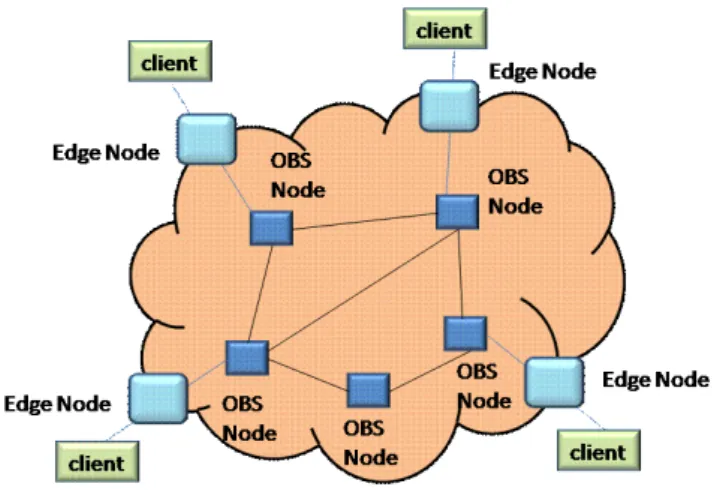
Fig. 1. Layout of the optical network
As the data remains optically, it is transported much faster as compared to the header. This results in too much overhead for the electronic processing with respect to the data part of IP packets. Therefore, it is proposed to transport the data no longer as separate IP packets, but to group them together to form bursts of variable length. Packets with same edge nodes and Quality of Service (QoS) requirements, will be put in the same burst and will have only one header, i.e., the Burst Header Packet (BHP). The remaining Data Burst (DB) is transmitted unchanged through the network, until it reaches the edge of the network. At the edge, the DB will be separated back into IP-packets [6].
To avoid contention of control information, the channels inside a fiber are divided into data channels and a few separate control channels. The BHP is sent in front of the DB on a separate control channel. These control channels are grouped together in the Control Channel Group (CCG). The DB is scheduled on one of the data channels by a scheduler. All the different data channels form the Data Control Group (DCG) for a single fiber [6].
A. Burst Assembly Algorithms
As explained in the earlier section, it is not possible to predict the burst length in advance, and hence, various burst assembly algorithm is presented in this subsection. Usually, assembly algorithms can be classified as timer-based, burstlength-based and mixed- timer/burstlength-based schemes[4].
In the timer-based scheme, a timer starts at the beginning of each new assembly cycle. After a fixed time T, all the packets that arrived in this period are assembled into a burst. In the burstlength-based scheme, there is a threshold on the (minimum) burst length. A burst is assembled when a new packet arrives making the total length of current buffered packets exceed the threshold.
The time out value for timer-based schemes should be set carefully. If the value is too large, the packet delay at the edge might be intolerable. If the value is too small, too many small bursts will be generated resulting in a higher control overhead. While timer-based schemes might result in undesirable burst lengths, burstlength-based assembly algorithms do not provide any guarantee on the assembly delay that packets will experience. To address the deficiency associated with each type of the assembly algorithms described, mixed-timer/threshold-based assembly algorithms were proposed in [5, 7]. For example, a burst can be sent out when either the burst length exceeds the desirable threshold or the timer expires [7].
B. Optical Burst Switching Protocol
C. Deflection Routing
The performance evaluation of the switches at the network layer is done in terms of packet loss probability. The performance of the switches also depends on the traffic models. Two traffic models are considered for the performance evaluation in this work.
Optical Burst Switching (OBS) is distinguished from other optical switching technologies due to its two features: 1) the transmission of large data bursts, which are aggregated at the edge of the network, and 2) the possibility to establish a path dynamically and on-the-fly (i.e. without acknowledgment of the availability of transmission resources). Because of the absence of optical buffering capabilities, the main challenge of OBS networks is to deal with high burst losses due to the contention of bursts transmitted in the network.
To mitigate the burst contention problem, many solutions based on deflection (or alternative) routing was proposed [11-12]. All these methods allow re-routing contending bursts from primary to alternative routes, and by these means, alleviating congestion on bottleneck links and achieving dynamic load balancing in the network.
In principle, the transmission of optical bursts is asynchronous in an OBS network, i.e., the bursts are not aligned each other, and they arrive at a core switching node in casual instances of time. Performance improvements can be achieved if synchronous operation is applied: in fact, in such a case, contention may occur only between entire data units and better transmission resource utilization can be obtained with simple contention resolution mechanisms [13].
IV.OBS NODE ARCHITECTURE
An OBS network consists of optical burst switches interconnected with WDM links. An optical burst switch transfers a burst from an input port to its destination output port. Depending on the switch architecture, it may or may not be equipped with optical buffering. The fiber links carry multiple wavelengths, and each wavelength can be seen as a channel. A burst is dynamically assigned to a channel. The control packet associated with a burst may also be transmitted over a channel, or over a non-optical network. The burst may be fixed to carry one or more IP packets. Currently, OBS networks do not exist. Optical burst switch architecture is described in [5]. In this article, various algorithms for scheduling bursts within an optical burst switch are also discussed.
At an OBS node, no synchronization/alignment of bursts is necessary unless the switching fabric operates in a slotted manner. In addition, fiber delay lines (FDLs) and wavelength converters which are optional, can help in reducing burst loss [14]. Currently, it is a challenge to implement an OBS switching fabric with hundreds of ports operating at a switching speed which is on the order of nanoseconds. Nevertheless, on-going research work has shown promise. In this paper, a node design for Optical buffering of the burst is discussed, where very simple node architecture is considered and it is easily scalable.
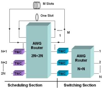
Fig. 2. OBS based Node Architecture
stored for a particular output port in all the modules, and in each module, N wavelengths are used. This will allow erasing of N packets in single time slot, one corresponds to each output. If the performance of the switch is optimized for M (M<N) number of modules, then rest of the ports of the AWG, i.e., N-M will be left free. Referring to Fig. 2, it can be observed that, between consecutive modules, N-1 wavelengths are common. Therefore in M modules, M+N-1 wavelengths will be required. The lower N ports (inputs/outputs port of the switch) ranges N+1 to 2N can be used for the direct transfer of packets. The lower ports are equipped with TWCs which tune the wavelengths of the incoming packets as per the desired output ports. The module 1 provides a delay of one slot, module 2 provide a delay of two slots and so on. Thus as per the required amount of delay, packets can be placed in different modules.
A. Bursty Traffic Model
In reality, data traffic is usually bursty in nature. In the bursty traffic arrivals are correlated i.e., packets arrive in the form of bursts. It is characterized by the offered load (ρ) and burst length (BL) [15]. Each burst of packets is equally likely to be destined to any of the output with probability 1/N.
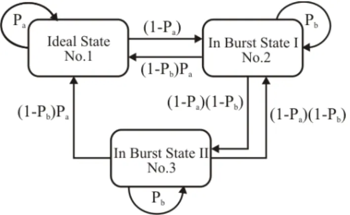
Fig. 3. Markov chain model for the bursty traffic
It implies that if a packet arrives on input i and destined for the output j in the current slot, then there is small but finite probability, that in the next slot packet arrives for the same destination. Thus, in the time domain, traffic at each input is composed of burst of packets destined for the same output. Time correlation of the traffic on each input is characterized by the Markov chain model (shown in Fig. 3). This model assumes three stages:
• Idle state
• Burst I state
• Burst II state
The system will be in idle state, if no packet arrives in current slot. With probability Pa, if no packet arrives
in the next slot, then burst will remain in the idle slot. Hence, a new burst probability (1- Pa) will start, and
system will go in the burst state I. Now considering a new burst with probability Pb
1) A new burst start for another destination with probability (1- P
will arrive for the same destination. The burst can terminate in two ways:
a) (1-Pb
2) By going to idle state with probability (P
),
a) (1-Pb
The steady state distribution of the Markov chain can be obtained as
��=�
).
where, π is row vector; �= [�1 �2 �3]� and P is transition matrix.
�
�
�(1
− �
�)
�
�(1
− �
�)
�
�(1
− �
�)
�
�(1
− �
�)(1
− �
�)
0
(1
− �
�)(1
− �
�)
�
��
�
�
1�
2�
3�
=
�
�
1�
2�
3�
with
� �
��
�=0
= 1
By solving the above equations, we get
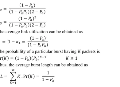
�2=
(1− ��) (1− ����)(2− ��)
�3= (1− ��)
2
(1− ����)(2− ��)
The average link utilization can be obtained as
� = 1− �1= (1− ��) (1− ����)
The probability of a particular burst having K packets is
Pr(�) = (1− ��)(��)�−1 � ≥1
Thus, the average burst length can be obtained as
��= � � . Pr(�) = 1 1− ��
∞
�=1
The performance of the switch is measured in terms of burst loss probability. The burst length is generated using the above model, thereafter Monte Carlo simulation is preformed to obtain steady state results.
V. RESULTS
The use of fibre delay for the buffering of the burst is not a feasible option as explained in earlier section. However, in the proposed architecture, only pieces of the fibre are used for the storage of the bursts. Hence, the architecture is very simple and provides very effective solution.
Fig. 4. Burst loss probability for switch size 4 and without any buffering capacity
In Fig. 4, we have plotted burst loss probability vs. load on the system, while assuming switch size of 4 with zero buffering capacity and burst length of 2. It is assumed that at each node, either the burst will be served or it will be deflected to some other node and will re-appear on the same destination node after some time. Since, each node cannot store burst, the buffering capacity is assumed to be zero. In Fig. 4, the burst loss probability is 26% for a load of 0.8, which is very large in number. However, this loss can be minimized by deflecting the burst to some other node. In such a case, the burst loss can be avoided. However, following problems may alleviate:
1. A large number of packets will travel in the networks. In this case, 26% of the arriving packets needs to be deflected. This process happens on the other nodes also. Hence, a large number of packets will move through the network and the network may easily get congested.
3. To address the above problem, there are algorithms that make sure that burst may not traverses too long in the network so it may come back to the destination node, however when burst traverse in the network unnecessary, unavoidable delay may happen.
4. While packets are deflected to some other nodes, their physical quality in terms of SNR ratio may become very lower, even in such a case when packet will re-appear on the same node, they cannot be detected properly.
It is clear and evident from the above discussion that the deflection routing is not an effective solution.
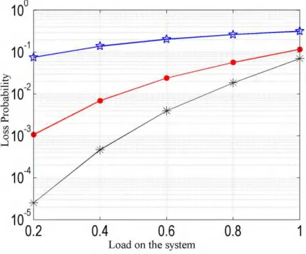
Fig. 5. Burst loss probability for switch size 4 and with varying buffering capacity
As already discussed, if each node is equipped with an OBS switch, which can store a burst for some finite duration, then the above stated problems (1-4) can be resolved. The simulation results with finite buffering capacity are shown in Fig. 5, where the buffering capacity of 4 bursts, each burst of length 2 is considered. At the load of 0.6, the burst loss probability improves by a factor of 10. Similarly, with buffering of 8 bursts, the loss probability further improves.
In real time, the burst length is not known. Hence, it is suggested to use both the buffering of packets as well as deflection routing. In a case of big burst arrival, which cannot be stored, it is better to deflect rather than drop the burst at the input of the switch. Hence, deflection routing in conjunction with buffering of burst will provide very effective solution.
VI.CONCLUSION
REFERENCES
[1] C. Qiao and M. Yoo, “Optical burst switching (OBS) – a new paradigm for an optical Internet,” Journal of High Speed Networks, Vol. 8, pp. 69-84, 1999.
[2] Masetti et.al., “Design and implementation of a multi-Terabit optical burst/packet router prototype,” in proc. Optical Fiber Communication Conference, 2002, pp. FD11–FD13.
[3] J. Turner, “Terabit burst switching,” Journal of High Speed Networks, vol. 8, no. 1, pp. 3–16, 1999.
[4] Y. Chen, C. Qiao and X. Yu, “Optical burst switching: A new area in optical networking research,” IEEE Network Magazine, Vol. 18, No. 3, pp. 16-23, May 2004.
[5] Y. Xiong, M. Vandenhoute, and H. Cankaya, “Control architecture in optical burst-switched WDM networks,” IEEE Journal on Selected Areas in Communications, vol. 18, pp. 1838–1851, October 2000.
[6] Serge Molenaa, “Performance study of scheduling algorithms for optical burst- switching core routers,” M.Sc. Thesis, Delft university of Technology, 2001.
[7] X. Yu, Y. Chen, and C. Qiao, “A study of traffic statistics of assembled burst traffic in optical burst switched networks,” in Proceeding of Optical comm., 2002, pp. 149–159.
[8] E. Varvarigos and V. Sharma, “The ready-to-go virtual-circuit protocol: a loss-free protocol for multigigabit networks using FIFO buffers,” IEEE/ACM Trans. Net.,vol. 5, Oct. 1997, pp. 705–18.
[9] I. Widjaja, “Performance analysis of burst admission-control protocols,” IEEE Proc. Commun., vol. 142, Feb.1995, pp. 7–14. [10] M. Yoo and C. Qiao, “Just-enough-time (JET): A high speed protocol for bursty traffic in optical networks,” in Proceeding of
IEEE/LEOS Conf. on technologies for a global information infrastructure, August 1997, pp.26–27.
[11] F. Borgonovo, L. Fratta and J. Bannister, “Unslotted deflection routing in all-optical networks,” IEEE GLOBECOM 1993, pp. 119-125.
[12] F. Borgonovo, L. Fratta and J. Bannister, “On the design of optical deflection routing networks,” IEEE INFOCOM 1994, pp. 120-129. [13] C. Gauger, “Contention resolution in optical burst switching networks,” in Advanced Infrastructures for Photonic Networks: WG 2
Intermediate Report, 2002, pp. 62–82
[14] J. Ramamirtham and J. Turner, “Design of wavelength converting switches for optical burst switching,” in Proceedings of INFOCOMM, 2002, vol. 1, pp. 362–370.